Mohammed Awwad Ali Al-Dabbas
© 2021 IIETA. This article is published by IIETA and is licensed under the CC BY 4.0 license (http://creativecommons.org/licenses/by/4.0/).
OPEN ACCESS
This study helps to make the sustainability of the experiential system reg of solar generator device better, particularly the unexpected inactiveness of drainage liquid throughout the solar system which is generating power. Stagnation situations can be disastrous for solar system units. Various methods to mitigating the consequences of the stagnation state have been established and tested. Some suggested approaches are not appropriate for all device designs and implementations. The tested reg generator systems in experiments can continue to work although the collector of the piping system is cut off. furthermore, the absorber layer is a challenge because it absorbs general solar incandesce regardless of cell temperature, causing the piping system to become inactive. This research depicts the experiential data that was tracked and mentioned in dealing with stagnation. The hydrodynamic flowing in the experiential solar generator was simulated using rigid flow. The measuring and processing of the data allowed the identification of excessive heat and stagnation issues in real-world operating environments. Daily, the test logging data of the prototype reg device was monitored to guide the incipience of inactivity and excessive heat. Most items have been utilized in the study; solenoid check valve and the Reflux Pipe in the Check Valves have been utilized as primary control items within the experimental reg unit, while normal cooling was utilized as the subaltern control element. Under stagnation phases, an air path is installed at the rear of the absorber to cool it normally. In general, there are agreement between the experimental and simulation results.
stagnation, inactiveness, solar generator, solid flow CFX, solenoid check valve, emptying of solar generator, temperature self-limiting, natural cooling, Reflux Pipe
The solar thermal collector generator is a heat exchanger system that accumulates solar energy and transforms the accumulated energy into thermal energy, which is then transforming radiation's calefactions into flowing liquid through the capacitor system [1-7].
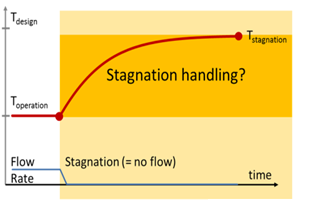
Figure 1 presents, the most frequent issues detected in solar systems are overheating and inactiveness, as those are a very critical factors in identifying the service life of an installation. That's also due to increasing temperatures which occur during periods of high solar irradiance. Since all of materials used in installation are manufactured of plastics, these values of temperature must be kept to a minimum [8-12].
This effect particularly common if we need a low energy need. This situation becomes much more pronounced when the transmission medium which transfers heat via the condenser is interrupted by a power deficit or element issues, causing stagnation.
The inactiveness temperature (stagnation) happens when the gained radiative heat equals the lost energy expended from the experiential generator device. Even though the experimental reg continually absorbing solar strength is available concentration, inactiveness determines the abruption and thermal disruption point of the experiential reg piping arranging. The thermal shock could reveal the entry solution on hot days, causing turbulence, vibrating, and destroying the power piping arrangement. Managing and controlling inactiveness encompasses all measures that can be applied to stop the emergence of a no-flow event [13-24].
Figure 1. Inactiveness handling in the solar collector (Elimar Frank, SPF (2014))
Inactiveness is a common issue with solar systems worldwide, particularly in hot, dry areas, and it is an outcome of poor system design or cost-cutting by a manufacturer. This occurs as the solar storage energy has reached its max temperature, but heat is still being stored in solar cells. This can happen on sunny days, even when the homeowners are out on vacation and no warm water has been drained from the storage reservoir.
While the liquid in the panels boiling to steam, it dilates dramatically, creating a pressure surge within the enclosed solar system that stresses got too hot fittings even more. When the solar panel starts to lose heat, and the overheated liquid is prepared for being condensed, the pressure will rise high well enough to release the device's pressure relief valve, spilling solar fluid into a holding container and creating a lack of system pressure.
As the solar reservoir reaches operating temperature, the solar pump turns off, and airflow inside the device is halted. Since the solar cell continues to generate heat and it cannot be switched off, it can reach the temperature that the solar fluid begins to boil.
One of the nearly all common significant difficulties for solar thermal process heat systems is dealing with stagnation and excessive heat conditions without risking system failure and necessitating further routine maintenance.
1.1 The primary target of our study
Many scientists proposed various methods for controlling the Inactiveness phenomenon. The following major topics are addressed in the presented article: specifies the idea of collector inactiveness and collector field Set up the experimental rig, avoid Inactiveness, and control steps for solar process heat implementations, analyze the testing rig. Furthermore, the discussed paper specifies the results of experiential and simulation analyses on the Inactiveness of a solar thermal process. At last, this concerned research reported the analyses of measurements taken on a solar thermal system situated at Mutah facilities. The outcomes of this research demonstrate how solar installations enter a state of stagnation. The following major topics are addressed in our research: Furthermore, the latest study involves sturdy flowing is being used to recreate and check the hydrodynamic flow within the Experimental solar generator.
The current study determines the benefits of reducing the inactiveness effect from Jordanian solar generators, as seen in Figure 1, The inactiveness method can be divided into five standard phases based on variations resulting from discrepancies. Three stages were performed out in the plant category: Stage 1 is the emptying of solar generator, Stage 2 is the liquid expansion, and Stage 3 is the refilling of solar generator.
1.2 Literature review
According to Eismann et al. [19], stagnation situations are any case where a solar collector is needed.
Collect heat from the sun's light and move it to the liquid, which is transferring heat, allowing solar generator and its elements to increase and reach a temperature more than the max recommended degree.
Inactiveness situations may occur during having sun's light when the liquid, which is transferring heat in the system is disrupted because of technical defects like system repair and maintenance, equipment problems, power cuts, and Due to capacity of storing limits, the pump controller intervenes, or some other cause for temporarily small heat demand.
The outcomes of ref. [7] indicate that inactiveness conditions were analyzed concerning variables like temperature reliance on thermal panel outputs and inputs, flow opening distance, sensor inclination angle 0 to 90 degrees, and operational requirements, with a focus on Emittingness. The study concentrated on platform-style boards cooled by air, which considerably alter the opportunities for traditional panel designs. As per the literature [16], one of the scientific solutions is the using of thermochromic absorber covering or painting, which allows for a substantial reduction in the capacitor and the temperature of the solar loop during inactiveness. Even so, this concept of deflation removal may only be applied with modern technical items. Another method of avoiding excessive heat by utilizing a new innovative coating, as defined in ref. [17]. Another alternative, as defined in ref. [18], is using butane gas to achieve heat transfer. The outcomes showed that using butane gas for transferring heat will restrict the max temperature in the system's solar loop to 120 C or less, allowing for better collector efficiency.
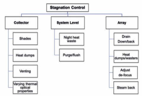
Figure 2. The different methods used to monitor or mitigate inactiveness conditions at the collector are depicted in the system situation. (i.e., operational), or solar array level [19]
The design provided [20] describes a modern strategy of aluminum heat pipes with limited copper usage. The highest Inactiveness temperature of this new kind of pipe is 140 Celsius.
Eismann et al. [19] outlined the impacts of inactiveness factors that were developed and tested. As seen in Figure 2, some suggested approaches really aren't appropriate for all systems and functions. The picking of stagnation dominate is affected by factors like storage and unit capability, load distribution, temperature and freeze safety standards. Furthermore, ineffectively executing systems that cannot rely on user or controller interaction or that do not need external energy to run appears to provide significant benefits in regarding effectiveness.
1.3 The benefit of preventing inactiveness
• The ability to utilize the advanced reg generator systems for a longer length of time would improve.
• The competence of the experiential reg generator will rise.
• The structure's conservation will be reduced.
• Defects and accidents can be eliminated.
Particular thermal inactiveness was reduced, eliminated, and concluded. The solar generator pilot rig system designed, assembled, and operated in Mutah laboratories, as seen in Figure 2. As a result, two distinct techniques have been utilized to depict stagnation handling areas in the generator system. One of those techniques clearly shows the experiential results that were tracked and documented in the processing of inactiveness. The other approach is to recreate the hydrodynamic flow within an advanced solar generator system using solid flow. The measures and analysis have allowed the identification of excessive heat and inactiveness issues in real-world operating environments. Every day, the experiment processing results of the experiential reg system were monitored to guide the presence of inactivity and overheating.
Several items have been used in the study; the Reflux Pipe in the Check Valves and solenoid check valve have been utilized as the main control element within the experiential reg system, while normal cooling has been utilized as an alternative control item.
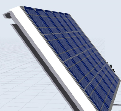
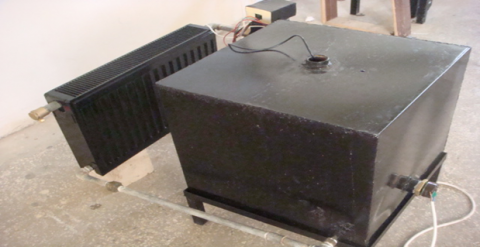
Figure 3 shows the solar generator's elements, which include: absorbing plate, covering glass shield vitrine plate, collector pipe, and adsorption plate, which were coated with an admixture of black paint and Nanoparticle to reinforce the unit's functionality, in addition to this an air conditioning appliance. In addition, a Nanoparticle was added to the collector accumulator liquid to enhance the pilot system efficiency. To subtract inactiveness, an air array piping was used. An air-cooling unit was set under the collector to reduce the Inactiveness [8-13].
Figure 3. Cross-section of the designed collector with ventilation path
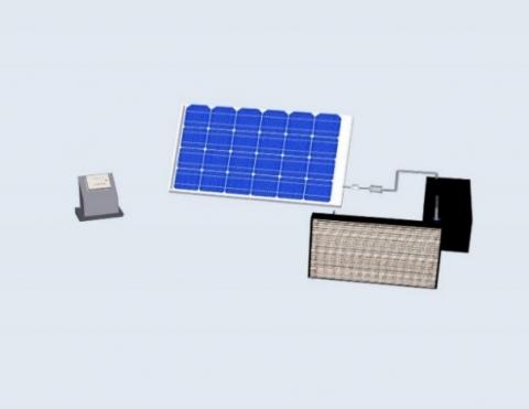
Figures 4-5 represent the prototype reg generator pilot design that has been set up at the University of Mutah's department of the manufacturing facility, additionally the flap taps arrangement, which was also utilized to expand the reservoir in helping to fulfill it with liquids from the supply and discharge lines. Most solar systems are designed to dissipate as little heat as possible into the environment, like solar panels with low heat-loss coefficients. The prototype reg system, as seen in Figure 2, was thoroughly monitored using many axially positioned elements.
The project of experimental reg units in Karak-Mutah (south of Jordan) considers that the liquid began pushing up out of the capacitor at the stage's end and concurrently as low as possible in terms of residual liquid substance inside the generator and to discharge thermal loads on the structural elements also the thermal conducting fluid. While functionality was being applied step by step, inactiveness was being guided. This task's generator assembly is a rectangular box with a glass covering layer, two collectors, the absorber layer, array piping: water, air, and insulators.
Figure 4. The pilot solar generator thermal rig Setup
Figure 5. The integrated solar generator cycle
3.1 Demeanor of inactiveness in experiential reg unit systems
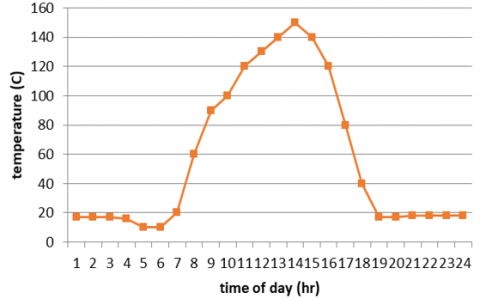
On hot days, interior array piping temperatures can exceed 170℃ during reduced heat removal times or power shutdowns. The thermal tensity and the pressures will quickly increase, and the accumulator elements can fail inside the array piping structure, posing a risk to nearby people.
A controlling technique was designed, developed, and tested to mitigate the effect of the solar thermal system's inactiveness (stagnation) thermal on temperature measurements.
The results of testing and monitoring this system showed that the levels of operating and processing in term photovoltaic in Jordan built to self-limit its higher indignation., the plan characteristic is of as leaden thermoregulator method the lack of consistency continuation interference over the user permanency or external limit source. The advantage likely of it is that it has little impact on the emulation of solar generator operation throughout.
Most solar water heaters SWH systems have the potential to achieve high temperatures for intensive heat outreach above 170 Celsius; the resulting “thermal loading” conditions would intensify the deterioration of “spectrally selective” solar absorbers, absorber coatings, and the water heated reservoir, likewise the water boiler.
Many solutions were tested and applied to control the inactiveness in the pilot system; the relevant approach which has been utilized was simple to apply, inexpensive and ran continuously without any technical issues. The near-surface or the surrounding temperature, the pressure inside the unit, solar strength, and temperature were detected and reported along with all possible inactiveness nodes inside the track thermal unit for the Summery month. Occasionally, an exposed unexpected inside the intake section of cold fluid occurs when:
• When the generator is restarted.
• When a thermal unit duty is resumed, resulting in extreme interior thermal shock.
3.2 During the reduction of inactivity, steps are taken inside the pilot system
The temperature into the generator and the conditions inside the pilot piping system are affected by the nature of the area, the environment, the system type, the necessary temperature readings of the system, fluid characteristics, wind speed, solar strength, the absorber layer, material kind, emittance, reflexivity, reflectively, coefficient of convection and added particle that was combined with fluid.
When the experiential system begins to operate, the thermal temperature degrees of the generator begin to rise until it exceeds 160℃; however, if no managing is performed, the experimental unit will be damaged and require repair.
The capability to reject absorbed environmental radiations in the generator cell is based on the inside temperature of the generator, which should be less than 160℃.
Inside the generator, the following stages will appear throughout the heating process:
• The accurate water temperature within the experiential reg system will rise as a result of heat gain until it enters the evaporation phase.
• In the expansion tank, the remaining steam goes down.
• The calefaction leads to a rising in the saturated steam boiling and leaves the collector as steam.
• The remaining liquid becomes heated to a very high temperature as the experimental reg device continues to accumulate energy. As an outcome, normal cooling will begin to refine the experiential reg system.
3.3 Attempts to resolve the issue of inactiveness
Previously, multiple methods were tried to guide the situation of inactiveness. This object aims to aid researchers in their approach to limiting the inactiveness process.
Several methods were tested and applied to control inactiveness in the experiential reg system; the appropriate solution must be simple to execute, inexpensive, and run continuously without any technical issues [13-21].
1) Heat dumps: ejection the overheat by weakening the generator; this reasonable recommendation was not included in this research.
2) This recommendation to add material to the generator liquid in array piping to reduce calefaction gain in the generator was not investigated or evaluated.
3) Using a heat exchanger condenser component to exclude energy and reduce the temperature of the absorber.
4) The Heat exchanger fluids to remove heat energy: this solution was not used and must be put in the experiential reg system, likewise the suggested avoidance and safety method.
5) Heat pipes made of low-pressure plastic must be connected to a limited expansion reservoir to reduce steam production in the experimental reg unit; however, the appropriateness of this recommendation was not tested or evaluated.
6) In both options of inactiveness monitoring and control at the panel, using electric blinds roll upwards and downwards also from one side to another, and this recommendation is neither tested nor evaluated.
7) Having shades: to minimize the reached solar energy by shading a part of the flat-plate generator, which is not a feasible option, this recommendation has been investigated and evaluated.
8) Natural ventilation Off-grid of the flat collector's generator: when the temperature equals 115℃ and higher, the absorber is cooled by the surrounding air temperature. This recommendation has been tested and evaluated.
9) Inside the solar concentrator within the generator, there are two arrays of piping fluids: When the absorber temperature reaches 100℃ and higher, a condenser heat exchanger has been utilized to transfer the steam energy generated in the main collector array piping into a secondary closed fluid array piping, and this recommendation has been tested and evaluated.
10) Making use of discharge unit of a generator: Discharging of the experiential reg system drain if there is no flow scenario, particularly there are no sunlights around. This appropriate recommendation has been tested and evaluated.
11) Increase the existence of layers between of absorption surface and the glass shell, which may be air or a metallic sheet such as aluminum or copper. This method has the capability to significantly reduce the inactiveness impacts; however, it was not tested and evaluated experimentally.
12) Using various types of conducting fluid heat pipes which can withstand high temperatures and thermal energy, such as aluminum heat pipes, which can decrease the inactiveness temperature to about 20℃, this recommendation has been tested and numerically evaluated.
13) Utilizing a different coating layer to the absorber plate. This recommendation is not tested and evaluated experimentally.
14) To reduction the inactiveness temperature, a modern polymer thermotropic glazed layer is being used, and This recommendation was not tested and evaluated experimentally.
4.1 Assessment of Jordanian solar generator experimentally [25-26]
We looked into the practical approaches for limiting inactiveness temperature in the flat-plate solar generator at some point in that guidance.
Mutah University's engineering faculty designed, produced, and connected the generator system. the relevant thermal parameters: temperature, compress pressure, and Solar acuteness were documented and reported. Underneath the absorber layer, an air pipe was fixed [12-13].
As an outcome, the solution to control inactiveness was accepted and completed, and the generator system was saved from destruction.
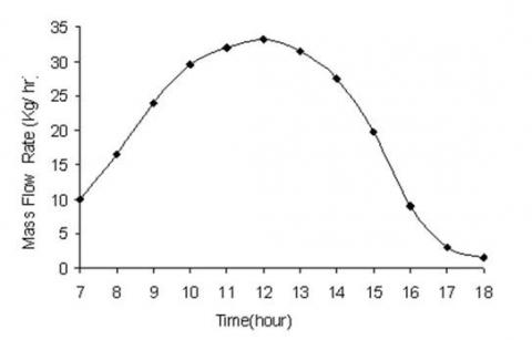
Figure 6 presents the behavior of volumetric flow rate of water documented in June within a time.
Figure 6. Volume flow rate of water versus time
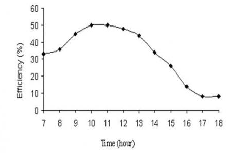
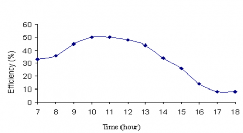
Figure 7 shows the weekly average instantaneous efficiency curves within a time.
Figure 7. The instantaneous professionalism versus time
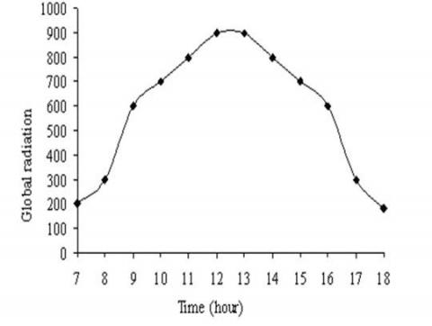
Figure 8 shows the solar concentration, Figure 9 shows the surrounding air temperature in June from 8:00 to 17:00.
Figure 8. Global radiation in June
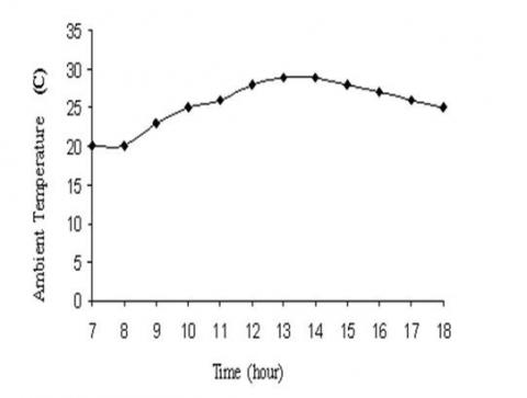
Figure 9. Sky temperature (C)
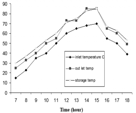
Figure 10 shows the thermal readings taken at inlet, outlet, and cylindrical water tank.
Figure 10. Warmth temperature of inlet, outlet and storage readings in June
Finally, Figure 11 shows the generator professionalism in June.
Figure 11. Generator professionalism in June
4.2 Strategy for minimizing inactiveness [13-24]
Figures 12-14 present the set of events that occur during inactiveness and can be separated into five stages [2, 7].
Somewhat various system behavior is found in case the check valve mechanism in the evaporation mode will not cause the expansion reservoir to be filled by liquid from both the returning and the flowing paths.
To reduce inactiveness, the adopted strategy was implemented during the process's operation:
Step 1: the experiential reg system is being emptied:
To prevent overheating, reduce inactivity time, and absorb remaining liquid growth from the conservator reservoir, the whole generator system should be empty. The drainage mechanism would assist the consumer in determining the inactiveness position, likewise the highest thermal temperature level of the experiential reg system, and keep it empty and its cycle time.
Figure 12 presents the experimental reg unit's emptying behavior along the day period if no precautions were taken.
Figures 13-14 show the benefit of the preventive performed actions on the generator on the pilot system.
Stages during inactiveness:
Utilizing a solar generator with a locked steam backup system: The closed receiver array piping fluid is being moved into an enormous tank, which would boil the liquid in a closed loop.
The position of the reflux pipe in flat-plate array piping has a major effect on the prevention of inactiveness. It must be fixed at the lowest point inside the drain back reservoir, with the gathered fluid drained back to the solar generator system array piping.
The off-grid expanding reservoir would be decreased to contain the excess moisture because of the inactiveness impact. The check valve will automatically open and shut depends on the precautionary measures taken by the experimental reg system.
Figure 12. Poor emptying behavior
Figure 13. Good emptying behavior
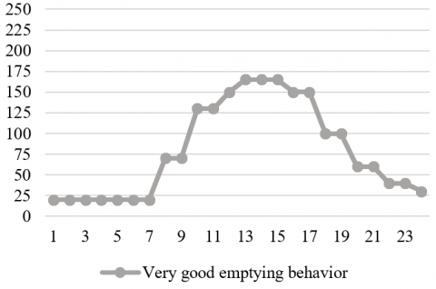
Figure 14. Very good emptying behavior
4.3 Measurement axillary
Many kinds of equipment were utilized during the experimental approach to decrease the influence of inactiveness:
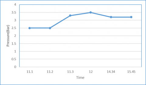
Figure 15. The expansion vessel pressure
Figure 16. System pressure within the generator
Measures to improve inactiveness in the face of an unfavorable emptying condition
In case that unfavorable:
In the situation of inactiveness, effective extraction of energy transported through steam is performed.
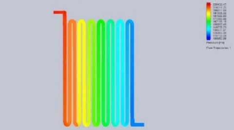
4.4 Simulation of solid flow using software
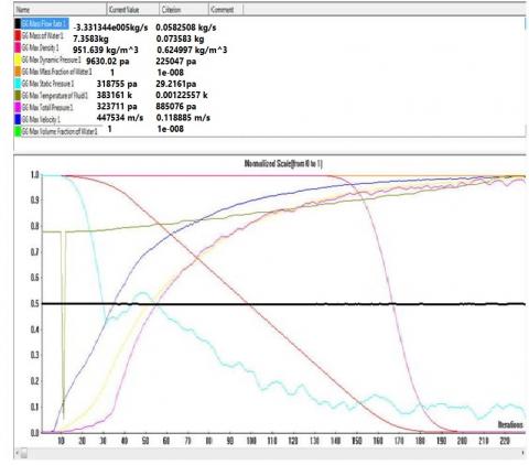
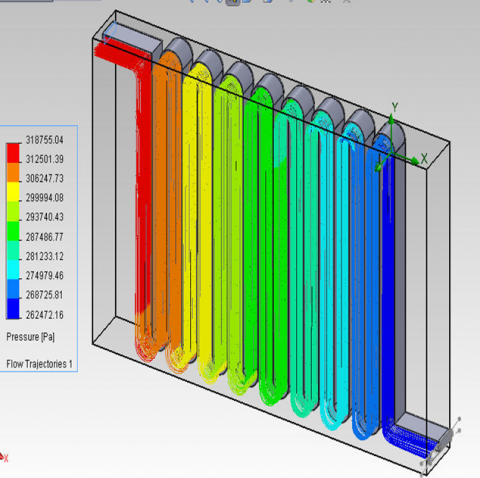
Figure 17. Hydrodynamic of storage
The software CFX for solid flow has been used to simulate the hydrodynamic flow within the Experiential solar generator system, As seen in Figures 17-25. The generator unit's designed grids were created, and the mandatory initial and boundary parameters were added.
The simulated results, as seen in Figures 17-25, agree with the experimental result which seen in Figures 12-16.
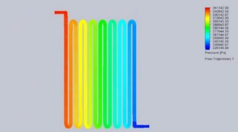
Figure 18. Pressure inside
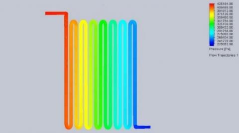
Figure 19. Poor emptying behavior
Figure 20. Good emptying behavior
Figure 21. Very good emptying behavior
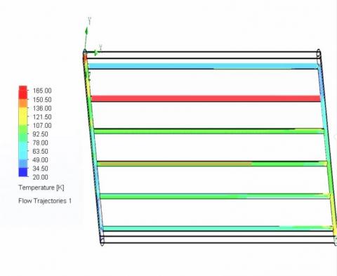
Figure 22. Temperature inside Radiator
Figure 23. Solar generator (Poor empity)
Figure 24. Solar generator (good empity)
Figure 25. Solar generator (very good empity)
Different techniques are now being used to reduce the effect of an inactiveness case; however, some of these solutions are not appropriate for all systems. Multiple conditions must be considered to reduce the inactiveness impact, including load, storage and unit capacity, dispensation requirements, climate changes, and temperature.
The technique of limiting the idle temperature and verifying its performance has been improved by experiments performed under “inactiveness” conditions.
Many approaches for dealing with inactivity were utilized, assessed, and examined.
[1] Duffie, J.A., Beckman, W.A. (2013). Solar Engineering of Thermal Processes. John Wiley & Sons.
[2] Köhl, M., Heck, M., Brunold, S., Frei, U., Carlsson, B., Möller, K. (2004). Advanced procedure for the assessment of the lifetime of solar absorber coatings. Solar Energy Materials and Solar Cells, 84(1-4): 275-289. https://doi.org/10.1016/j.solmat.2004.01.041
[3] Botpaev, R., Louvet, Y., Perers, B., Furbo, S., Vajen, K. (2016). Drainback solar thermal systems: A review. Solar Energy, 128: 41-60. https://doi.org/10.1016/j.solener.2015.10.050
[4] Hussain, S., Harrison, S.J. (2017). Evaluation of thermal characteristics of a flat plate solar collector with a back mounted air channel. Applied Thermal Engineering, 123: 940-952. https://doi.org/10.1016/j.applthermaleng.2017.05.121
[5] Bertsch, F., Jaehnig, D., Asenbeck, S., Kerskes, H., Drueck, H., Wagner, W., Weiss, W. (2014). Comparison of the thermal performance of a solar heating system with open and closed solid sorption storage. Energy Procedia, 48: 280-289. https://doi.org/10.1016/j.egypro.2014.02.033
[6] Berner, J. (2011). Generating inexpensive solar heat. Sun and Wind Energy, 2: 54-57. https://www.osti.gov/etdeweb/biblio/21412341
[7] Morhart, A. (2010). No standstill in the solar circuit. Sonne Wind und Waerme.
[8] Weiss, W. (2019). Solar Heating Systems for Houses: A Design Handbook for Solar Combisystems. First edition, Routledge.
[9] Hillerns, F. (2001). The behaviour of heat transfer media in solar active thermal systems in view of the stagnation conditions. IEA-SHC Task, 26.
[10] Freeman, J., Hellgardt, K., Markides, C.N. (2015) An assessment of solar–thermal collector designs for small-scale combined heating and power applications in the United Kingdom. Heat Transfer Engineering, 36(14-15): 1332-1347. https://doi.org/10.1080/01457632.2015.995037
[11] Weiss, W. (2000). Solar combisystems-task 26. International Energy Agency, Industry Workshop Borlange, Sweeden.
[12] Suter, J.M., Bergmann, I. (2003). Industry Newsletter: An yearly update for industrial companies. Nr. 3, International Energy Agency SHC - TASK 26. Solar Combisystems, Industry Workshop Borlange, Sweeden.
[13] Rimar, M., Fedák, M., Váhovský, J., Kulikov, A., Oravec, P., Kulikova, O., Smajda, M., Kana, M. (2020). Performance evaluation of elimination of stagnation of solar thermal systems. Processes, 8(5): 621. https://doi.org/10.3390/pr8050621
[14] Harrison, S., Cruickshank, C.A. (2012). A review of strategies for the control of high temperature stagnation in solar collectors and systems. Energy Procedia, 30: 793-804. https://doi.org/10.1016/j.egypro.2012.11.090
[15] Hausner, R., Fink, C. (2002). Stagnation behaviour of solar thermal systems: A report of IEA SHC 26, Solar Combisystems.
[16] Streicher, W. (2001). Minimising the risk of water hammer and other problems at the beginning of stagnation of solar thermal plants—A theoretical approach. Solar Energy, 69: 187-196. https://doi.org/10.1016/S0038-092X(01)00018-4
[17] Abd-Elhady, M.S., Serag, Z., Kandil, H.A. (2018). An innovative solution to the overheating problem of PV panels. Energy Conversion and Management, 157: 452-459. https://doi.org/10.1016/j.enconman.2017.12.017
[18] Sahu, S., Vadivukkarasan, M., Suman, D., Ramanjaneyulu, D. et al. (2019). Experimental investigations of stagnation temperature and overall heat transfer coefficient of flat receiver for solar parabolic dish concentrator system. Journal of Physics Conference Series, 1276(1): 012053. https://doi.org/10.1088/1742-6596/1276/1/012053
[19] Eismann, R., Hummel, S., Giovannetti, F. (2021). A thermal-hydraulic model for the stagnation of solar thermal systems with flat-plate collector arrays. Energies, 14(3): 733. https://doi.org/10.3390/en14030733
[20] Frank, E., Mauthner, F., Fischer, S. (2015). Overheating prevention and stagnation handling in solar process heat applications. International Energy Agency-Solar Heating and Cooling Task, 49. https://doi.org/10.13140/2.1.2166.9120
[21] Hussain, S., Harrison, S.J. (2015). Experimental and numerical investigations of passive air cooling of a residential flat-plate solar collector under stagnation conditions. Solar Energy, 122: 1023-1036. https://doi.org/10.1016/j.solener.2015.10.029
[22] Magalhães, P.M., Martins, J.F., Joyce, A.L. (2016). Comparative analysis of overheating prevention and stagnation handling measures for photovoltaic-thermal (PV-T) systems. Energy Procedia, 91: 346-355. https://doi.org/10.1016/j.egypro.2016.06.282
[23] Quiles, P.V., Aguilar, F.J., Aledo, S. (2014). Analysis of the overheating and stagnation problems of solar thermal installations. Energy Procedia, 48: 172-180. https://doi.org/10.1016/j.egypro.2014.02.022
[24] Gang, P., Jing, L., Jie, J. (2011). Design and analysis of a novel low-temperature solar thermal electric system with two-stage collectors and heat storage units. Renewable Energy, 36(9): 2324-2333. https://doi.org/10.1016/j.renene.2011.02.008
[25] Al-Dabbas, M.A. (2015). Performance evaluation of hybrid photovoltaic and thermal solar collector in Jordan. Distributed Generation and Alternative Energy Journal, 30(2): 8-22. https://doi.org/10.1080/21563306.2015.11431661
[26] Al-Dabbas, M.A. (2008). An experimental, mathematical model & computer program developed for isotropic and anisotropic modeling of tilt and azimuth angles of solar radiation in Amman, Jordan. Australian Journal of Basic and Applied Sciences, 2(4): 1186-1203.