Salmi Samsudin* | Nuraini Abdul Aziz | Abdul Aziz Hairuddin | Siti Ujila Masur
© 2021 IIETA. This article is published by IIETA and is licensed under the CC BY 4.0 license (http://creativecommons.org/licenses/by/4.0/).
OPEN ACCESS
Different types of coal have different characteristics and performances. In thermal coal plant, deposition of coal ash inside the furnace causes slag formation inside the boiler rear path and consequently reduces the heat transfer process and boiler efficiency. Besides, accumulation of ash on the boiler tube surfaces form layers of slags and blocks the flue gas flow out of the boiler. Therefore, the purpose of this study is to investigate the relationship between sub-bituminous coal base acid ratio towards the heat transfer process inside large-scale boilers. The base acid ratio for sub-bituminous coal is measured before firing inside large-scale boiler of studied the thermal plant which has a generation capacity of 700 MW. This study found correlation between high furnace rear path temperature (FRPT) that is observed to be above 800℃, with the build up of ash accumulation inside the boiler, for the studied coal. Thus, a high base acid ratio causes the accumulation of coal ash, thus reducing the heat transfer process which results in high FRPT of the boiler. Therefore, it proves that a base acid ratio is an indicator for coal performance during firing inside the boiler.
boiler, coal ash, base acid ratio, ash slagging
A thermal coal power station is a type of power station that produces electricity based on combination of heat energy system and heat transfer process. The heat energy is converted to electric power. In most design, a steam-driven turbine converts heat to mechanical power as an intermediate to electrical power. The boiler purposely is a chamber to occupy the combustion process inside the furnace that is filled with boiler tubes [1, 2].
In thermal plants, the combustion process involves coal and gas as the main fuel for combustion. In fact, coal is selected by most of the Asian country due to cheaper price as compared to natural gas and distillate. According to Zhang et al. [3], coal is an organic sedimentary rock that forms from the accumulation and preservation of plant materials, usually in a swamp environment. Coal is a combustible rock and, along with oil and natural gas, it is one of the three most important fossil fuels [4, 5]. Coal as a fossil fuel have rich mineral contents such as carbon, hydrogen, nitrogen, acid, and alkaline. However, coals with specific mineral contents may impact towards the coal burning characteristic during the combustion process.
Concurrently, ash is the predominant combustible by-product of coal. Coal ash is defined as the mineralized residue which is left over from burning coal during the combustion process [6, 7]. Moreover, fly ash coal can cause slagging and fouling inside the boiler furnace. The slagging and fouling is formed due to accumulation of coal ash which is transported through the flue gas. Based on the deformation mechanism, the accumulated ash is defined as slagging and fouling. The formation of molten ash with partial fused deposits on the furnace walls of the boiler is namely defined as slagging [3]. Slagging deters the heat transfer process which occurs through convection. Meanwhile, according to Salmi and Nuraini [8], fouling is the formation of ash at the superheater and reheater area which causes ash deposition onto the convection heating surfaces. During coal combustion, large amount of ash is produced along with carbon dioxide and other gases. The fine particle ash that rises up with the flue gases is known as a fly or flue ash while the heavier ash that does not rise is called bottom ash.
In the prediction of coal ash slagging and fouling, most researcher measures the coal base acid ratio. Coal base acid ratio is applied to predict the potential of slagging and fouling that occurs inside the boiler [5, 9, 10]. By doing this, the operator can plan and manage coal scheduling to meet the desired boiler parameters. Plant corrective action and boiler operation can be managed properly by measuring the potential of slagging and fouling inside the boiler furnace [5, 11]. As mentioned by most researchers a clean boiler tube surface results in maximum heat absorption [12, 13]. Prediction and early detection of coal behaviour during combustion in the boiler are most useful in managing the boiler operational parameters [14, 15].
The operation of the power plant follows the steam cycle concept of the Rankine Cycle. However, for actual performance, the thermal efficiency for the plant is between 30-36% for sub-critical boilers and supercritical boilers [3, 13]. Factors that influence the thermal plant efficiency includes the type of fuel, combustion performance, machine technology, quality of material, and operational effectiveness [6, 16]. All factors mentioned have been successfully implemented in various industrial boilers, however the performance of such boilers tend to vary with its designed material and philosophy.
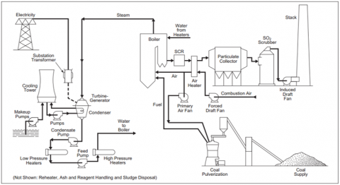
Thermal plants are design based on complex close circuit system. The water treatment process is a critical system for producing demineralized water. The Water Treatment Plant (WTP) is an auxiliary system to ensure that the demineralized water produced, meets the required water quality for the safe continuous operation of the boiler [13]. The de-mineralized water is introduced in the condenser hot well where it is mixed at the same time with heated water extracted from the turbine. Figure 1 shows the typical process diagram inside thermal plants [6, 16].
Figure 1. Thermal plant process diagram
The Condensate Extraction Pump (CEP) is responsible for transporting water from the hot well into the feed water system at high-pressure. The incoming feed water is preheated from tapping lines that are connected to the turbine system. To improve thermal efficiency, the incoming feedwater is heated by a series of pre-heaters, known as low pressure heater 1 (LPH1) and low pressure heater 3 (LPH3) which are connected in series to one another.
The feed water system is transporting the water with temperature and pressure. This system starts from the deaerator tank until the feed water stop valve. This system is responsible for maintaining water level inside the boiler drum, which consequently fluctuates due to on-going phase change of water due to evaporation and heating process [16, 17]. To boost up the water pressure from the deaerator storage tank, a boiler feed pump (BFP) is installed. The installed BFP pumps the water through the common header line and diverts the water flow into the high-pressure heaters (HPH). Normally, the HPH system consists of different levels of HPH at different temperatures such as HPH5, HPH6, HPH7, and HPH8. The quantity of the HPH stage is subjected to the desired design of the thermal plant. The build up mechanism of the HPH consists of water tube and shell which is similar to the boiler drum function [1, 16].
From there, the feed water flows through the tubes of the HP feed water heaters and into the boiler economizer. Water from the condensate system passes through the economizer section before it arrives at the boiler drum. The system is a continuous circulation, supplying the water from feed water system into the boiler drum for conversion into steam. This circulation system is constant and operates continuously to ensure sustainable steam production inside the boiler drum [16, 17].
Superheated steam with high pressure and temperature produced at the boiler drum is then passed into the turbine system. Energy conversion from thermal energy into kinetic energy happens during the rotation of the turbine blades. The rotation of the turbine produces energy exchange at the coupled generator and stator system which converts the kinetic energy into electrical energy [14, 16, 17]. The fundamental of thermal plant is based on the Carnot Cycle theory. However, the Carnot cycle describes the perfect condition of thermal plant with optimum performance and efficiency [6, 13, 17].
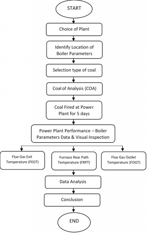
To meet the study purpose, a research framework was developed and established accordingly. The research framework was form based on a flowchart chart process. The flowchart process consists of steps for choice of plant type, identification of boiler parameters, coal selection, power plant performance monitoring, visual inspection, data analysis, and conclusion. The flowchart proses is presented in Figure 2 below.
Figure 2. Research framework
In ensuring the study is beneficial to the industry, the experiment was conducted at one of largest thermal coal-fired power plants in Asia. This particular plant was commissioned in 2003 with 700 megawatts generating capacity. During the commissioning stage, the plant was fine tuned to fire sub-bituminous coal types as its main fuel. The boiler operation is premediated for continuous operation [13]. The boiler is capable to perform combustion in the furnace chamber with a designed balance draught system and using tangential firing. The maximum heat input that can be achieved when firing fuel oil is only 40 percent of the Boiler Maximum Continuous Rate (BMCR) [16, 17].
The plant is installed with 7 pulverizers of vertical bowls types. For full generating capacity of 700 megawatts, only 6 pulverizers are required to be in service. The light fue loil (LFO) is mainly used for boiler start-up and initial coal ignition. The LFO is also required for combustion stabilization and to support the start-up of the pulverizer. The arrangement of the LFO burners is based on the furnace level and is not required to be put in service once the pulverizer is fully operating [14].
The boiler is designed with a hollow furnace measuring 19.5 wide x 18.4 m depth. In the boiler, combustion occurs inside the furnace and consequently allows for heat transfer to take place at the walls tubes prior to carrying saturated steam into the boiler drum. The boiler drum is covered with insulation to protect and avoid direct contact with the hot flue gasses. The steam is superheated before passing through the boiler and into the prime mover, which is the steam turbine. The fuel is burnt inside the furnace of the boiler [1, 5]. To achieve optimum efficiency, sufficient air must be supplied [13]. Air supply mechanism is compressively supplied by the draught system. The draught system includes an induced draught fan, primary air fan, and force draught fan. In addition, the draught system is installed together with a dispersion chimney that is induced by an additional draught fan. Heat is produced during the combustion of the fuel. The gaseous products generated during combustion, transfers most of their heat to the water inside the tubes of the boiler and superheaters. In order to make use of the remaining heat, the gases are made to pass through an economizer thereby heating the feedwater inside the economizer tubes.
The combustion air is supplied through the corners of the boiler to mix the incoming fuel with oxygen. The arrangement of fuel and combustion air is staged at the same corner but at different vertical level. This arrangement is purposely to ensure sufficient air is supplied to ensure complete combustion [11, 18].
The flow provides a rotation motion to the flame and creates additional turbulence for additional mixing of fuel and air. The flame spreads in the furnace and produces a “fireball”. The fireball is located at the center of the boiler to ensure uniform heat transfer is distributed along the water wall boiler tube. To ensure the fuel is completely combusted inside the furnace, the fuel is resized into small surface area by the pulverizers. [11, 14]. Such characteristics ensures sufficient lead time is adequate for complete combustion inside the furnace. The operation of this thermal coal plant was designed for automatic control with minimal interruption required by humans through the Human Machine Interface (HMI). However, the operator is allowed to operate and take action during the operation when necessary. The operation of this thermal coal plant is in accordance with the thermodynamic process, where heat energy generated is in line with the principle of heat transfer [16-18]. Figure 3 shows the schematic diagram process at this thermal coal-fired power plant.
Figure 3. Schematic diagram process for thermal coal fired power plant
Sub-bituminous coal was selected as the original design and preferred coal for this particular plant. Five types of sub-bituminous coal were used during this study as shown in Table 1 where the boiler was fired with each coal type for 5 days continuously without any interruption. Data was collected based on the numerical plant performance data. Analysis of the boiler parameters were captured and analysed accordingly.
As mentioned previously, each coal specification was analysed thoroughly, where the measurement of coal base acid ratio was performed. The ratio of base to acidic oxides is expressed by the ratio of basic oxide, B to the acid oxide, A. B/A has been described by Frandsen [5].
B=% Fe203 + % CaO + % MgO + % Na20+ % K20
A=% Si02 + % Al203 + % Ti02
Numerically the ratio is expressed using the following formula:
$\mathrm{B} / \mathrm{A}=\frac{\mathrm{Fe} 203+\mathrm{CaO}+\mathrm{MgO}+\mathrm{K} 2 \mathrm{O}+\mathrm{Na} 2 \mathrm{O}}{\mathrm{SiO} 2+\mathrm{Al} 203+\mathrm{TiO} 2}$
(Source: Frandsen, 1997)
Each coal type was then tested to identify the respective characteristic using the ultimate analysis and approximate analysis method. The respective coal was then further analyzed to quantify its calorific value, carbon, hydrogen, nitrogen, oxygen, ash content inside the coal [5, 19]. The Hard Grove Index (HGI) for each specific coal was subsequently tested to determine the coal hardness before firing at the plant [4]. The suitable HGI for this plant is between 40 to 50. From the coal analysis and specification, the formula was applied in measuring the base oxide, acid axide and base acid ratio for each type of coal [3, 13].
From the analysis, the base acid ratio for coal type A and coal type C indicates a low-level potential for slagging, while coal type D and coal type E were recorded to be within the range of moderate. Coal type B indicates a 1.25 base acid ratio which is a high potential of ash slagging, as indicated by a value that is above 0.7. However, the base to acid ratio should not be used as a single parameter to judge the ash deposition propensities, especially not if its value is below 0.1 or above 1.0 [5, 8]. The ratio reflects the melting potential of ash and has been related to viscosities and ash fusion temperatures [8, 18]. With most ashes, a B/A values within the range 0.4 to 0.7 indicate low ash fusibility temperatures and there by a higher slagging potential [5, 6].
Table 1 shows the coal specification and base acid ratio for each coal type that were used in this study. From the table, Coal type A has the lowest CV at 4819 kcal/kg and while coal type E has the highest CV at 5414 kcal/kg. Coal type B recorded a base acid ratio of 1.25, concurrently coal type C recorded a value of 0.27 and for coal type D the value was 0.61. Typically, the ratio of base acid tends to increase with higher coal CV [5, 8, 20].
Coal has many mineral contents which may affect the boiler performance and operational parameters [6]. To ensure other mineral contents will not affect the experiment, a complete combustion was ensured throughout the experimental period. This is important to ensure all mineral contents of the coal will be fully fired inside the boiler furnace [13, 18]. Besides, the unburn carbon samples during the combustion process is taken upon completion of firing throughout the experimental period. The unburn carbon indicates the combustion performance inside the boiler furnace where a value that is less than 2% of unburn content indicates a good combustion performance [4, 12, 18].
Table 1. Coal specification
|
Coal Specification |
Unit |
Coal Type |
||||
|
A |
B |
C |
D |
E |
||
|
Calorific value |
kcal/kg |
4819 |
4,927 |
5156 |
5354 |
5414 |
|
Carbon |
% |
73.60 |
68.26 |
74.04 |
74.82 |
74.12 |
|
Hydrogen |
% |
5.36 |
4.86 |
5.30 |
5.26 |
5.46 |
|
Nitrogen |
% |
0.97 |
1.17 |
1.46 |
1.69 |
1.33 |
|
Oxygen |
% |
19.93 |
21.52 |
18.59 |
17.43 |
18.96 |
|
Ash |
% |
1.70 |
3.04 |
6.30 |
5.00 |
5.70 |
|
Moisture |
% |
29.00 |
24.99 |
22.30 |
22.00 |
20.40 |
|
Sulphur |
% |
0.10 |
0.09 |
0.43 |
0.60 |
0.70 |
|
HGI |
Number |
47 |
54 |
44 |
48 |
41 |
|
Basic Oxide |
% |
15.42 |
52.21 |
19.77 |
28.42 |
36.19 |
|
Acid Oxide |
% |
49.04 |
41.79 |
73.37 |
46.48 |
59.74 |
|
Base Acid Ratio |
Number |
0.31 |
1.25 |
0.27 |
0.61 |
0.61 |
As mentioned before, five types of sub-bituminous coal were involved for this study. During the firing period, critical boiler parameter readings were taken and recorded accordingly. As shown in Table 2 where the boiler was fired with the different coal types for 5 days continuously without any interruption. Data were collected using the numerical plant performance value.
Table 2. Boiler parameters
|
Boiler parameters |
Unit |
Coal Type |
||||
|
A |
B |
C |
D |
E |
||
|
Load Generation |
MW |
701 |
702 |
700 |
700 |
699 |
|
Superheated steam temperature |
℃ |
540 |
541 |
541 |
542 |
540 |
|
Reheater steam pressure |
bar |
535 |
540 |
541 |
541 |
540 |
|
Superheated steam pressure |
℃ |
188 |
187 |
186 |
187 |
188 |
|
Reheater steam pressure |
bar |
32.2 |
33.0 |
32.5 |
32.1 |
32.5 |
|
Oxygen |
% |
2.53 |
2.51 |
2.55 |
2.51 |
2.55 |
Boiler parameters and performance value were continuously monitored on a 24 hours basis by operators on duty. The operator log sheet was prepared to record any abnormalities and findings during the testing period. From the recorded data, the plant was performing within the design limit and indicates normal behavior. Boiler parameters such as steam temperature and pressure, reheater temperature were behaving within range.
Subsequently, particular observation was carried out for boiler parameters that focuses on the flue gas path flow. This includes parameter readings such as furnace exit gas temperature (FEGT), furnace rear path temperature (FRPT), flue gas outlet temperature (FGOT), temperature inside the combustion chamber or namely known as boiler furnace temperature, de-superheating spray water flow and unburn carbon.
FEGT is located at the boiler furnace, just above the combustion zone while the FRPT reading is measured at the pendant tube area [2, 10]. FGOT indicates the temperature of flue gas flowing near the economiser tube area. There are 6 units of stop watches available for data collection during execution of the test. The standardised Resistance Temperature Detector (RTD) is installed together which located at the boiler. The boiler unit was maintained at a generating base load of 700 megawatts during the test period. To ensure data was constantly recorded, there was no transient load intervention allowed. No equipment testing or machine change over were carried out during the interval.
According to the Power Purchasing Agreement (PPA), the plant is required to continuously generate a base load of 700 MW, for which 10% of the generated load shall be used for internal auxiliary power consumption. Identification of location is important to determine the right area for the accumulation of slagging and fouling. In between the time lapse for accumulation, it is deemed that the operators are able to manage the condition of the boiler by taking fast remedial action. Figure 4 shows the location of temperature for FEGT, furnace temperature, furnace hopper temperature, and FRPT inside the boiler.
Figure 4. Location of boiler temperature measurement
Figure 5. Boiler parameters for each types of coal
5.1 Boiler parameters
Monitoring the boiler temperature at the boiler furnace exit region and maintaining them below maximum temperatures ensures appropriate combustion within the furnace and negates furnace tube overheating. For this study, the operating furnace temperature and FEGT for each type of coal were recorded to be below the ash melting temperature for each respective coal. The obtained FEGT reading must not be more than the Initial Deformation Temperature (IDT) of each coal types to avoid from high amount of fouling at the boiler tubes [10, 14]. IDT is an indication of the temperature at which ash begins to melt and accumulate. IDT is a specific stage of Ash Fusion Temperature (AFT), indicating certain property that governs the behavior of ash. In addition, AFT indicates the temperature range for a possible formation of the deposits on the heat adsorbing surfaces [1, 10].
Generally, for reliable operation of the boiler, it is important to measure the melting temperature of ash. Melting temperature for low meltable ash of ashes is from 1000℃ to 1200℃, while for medium meltable ashes the value would range from 1200℃ to 1450℃, and for heavy meltable ashes the value is over 1450℃. Therefore, it is important to measure FEGT readings, to ensure the temperature is lower than the melting temperature of ash being used [1, 10]. For this study, all types of coal show a low meltable of ashes properties, where the obtained FEGT readings were below 1200℃ except for coal type A. According to the certificate of analysis for coal type A, the AFT for this coal is 1250℃ which is above the operational FEGT range. Due to that, the potential of ash melting is low [10, 12].
Heat transfer at the superheater and reheater area occurs via a combination of convection and radiation mode, for which the heat medium is carried by the combustion flue gas. The temperature condition of the flue gas is represented by the Furnace Rear Path Temperature (FRPT). [10, 12]. A high furnace rear path temperature significantly results in high temperature of the flue gas outlet and can affect the gas recirculation system inside the boiler as well as heat transfer process at the heaters as presented by Song et al. [21]. However, to reduce the heat transfer rate at the particular area, the volume of oxygen can be adjusted and reduced.
From the result of this study, coal type D recorded the highest FRPT at 819℃ as compared to other coal types which was below 800℃. It means that for high FRPT measurement, the heat absorption is less due to the accumulation of ash coal at the pendant tube area. Due to that, the heat transfer at the area is insufficient and requires more heat to achieve the desired temperature. The worst case of ash accumulation, causes the superheated steam temperature to drop until 535℃ from 545℃ and consequently impacts the unit heat rate and efficiency [8, 14].
A desuperheating system or namely a spray water system was installed purposely as a tool for controlling the boiler temperature [10, 18, 20]. Besides, the desuperheating spray water flow is an indication of water flow required to meet the superheated temperature and reheater temperature. If the amount of spray water is high, it indicates that the amount of ash accumulating at the particular area is significant.
A high spray water flow means that the superheated steam and reheater steam temperature is above limit and needs more water to cool down the temperature. For this study, coal type B and coal type D shows high spray water readings, which was above the 100 tonnes/hrs limit as compared to nominal values obtained when burning coal type A, coal type C and coal type E. Figure 5 shows the boiler temperature parameters for each type of coal.
5.2 Emission control
The emission from coal combustion releases various gases to the atmosphere. In fact, coal combustion releases certain type of greenhouse gases such as carbon dioxide (CO2) and nitrous oxide (CO2) during combustion. There are seven principal oxides contained inside the coal, such as SiO2, Al2O3, Fe2O3, CaO, MgO, TiO2, Na2O and K2O. This oxide minerals correlates with the ash fusibility and potential for ash accumulation, ash slagging and ash fouling. Thus, the combustion output for various coal with different percentages of the mineral was measured in this study. The maximum allowable limit for emission at this plant; SO2 is 750 mg/Nm3 for SO2, 650 mg/Nm3 for NOx and 200 mg/Nm3 for CO. Based on the results, the emission reading for all types of coal were within acceptable limits. Figure 6 shows the average parameters as well as trending for emission control for this power plant, where limits for NOX, SO2, CO, and O2 were measured on a daily basis.
Figure 6. Average emission for each type of coal
Table 3. Emission parameters
|
Emission Parameters |
Unit |
Coal Type |
||||
|
A |
B |
C |
D |
E |
||
|
Unburnt Carbon |
% |
0.31 |
0.55 |
0.26 |
0.29 |
0.62 |
|
NOX |
% |
239.1 |
283.4 |
274.6 |
352.5 |
238.0 |
|
SO2 |
% |
176.7 |
144.0 |
266.5 |
259.4 |
167.3 |
|
O2 |
% |
6.59 |
3.59 |
4.69 |
4.92 |
4.36 |
|
CO |
% |
27.65 |
28.89 |
29.06 |
30.12 |
27.58 |
For thermal coal plants, the unburned carbon in fly ash is an important indicator of boiler combustion efficiency. Unburned carbon in the flue gas cannot be eliminated fully but can be reduced to a significant amount. Besides, readings for unburnt carbon, NOX, SO2, CO2 and O2 released together with the flue gas must be continuously monitored to meet the environmental limits. Table 3 shows the parameters for emission control. The best level of unburnt carbon is estimated to be around 2-5 percent from the total fly ash content. Unburned carbon in fly ash is an indicator of inefficiency in the combustion process and an excessive proportion of unburned carbon in the fly ash means a significant loss in energy in power generation.
5.3 Physical inspection and observation
Inspection and site observation at the superheated area, burner, and bottom ash hopper were carried out for the experiment. Slagging was observed at the furnace walls, superheated area, reheater area, rear pendant tube.
Typically for coal with a low base acid ratio with ash percentage above 3 percent, the ash is found in a brittle manner and mainly consists of “clay-type” components of the ash. For both coal type A and C, the coal ash slag is observed to be easily removed by carrying out soot blowing process. High temperature fouling at the superheated area is quite minimal and the thickness stays more or less the same throughout the trial burn period. Fouling at the second pass is very minimal, as induced draught fan suction doesn’t impact much toward its formation [3, 12, 13].
Figure 7 shows the boiler tube condition at the superheater area as observed through the boiler inspection door and also at the submerge scrapper conveyor for bottom ash observation.
Figure 7. Boiler inspection and observation
Coal type B, coal type D and coal type E with a base acid ratio above 0.4, illustrated a medium range of slagging potential. It was observed at the site, that the heavy ash coal slagging at the boiler tube area could easily be removed by carrying out repeating soot blowing process at the selective area. Coal type B recorded a high potential for slagging, however, the percentage of ash content for this coal is considered low which is at 3.0 percent only. Thus, the potential of ash slagging is very minimal and still easy to be removed. Figure 8 shows the coal ash slagging at the boiler pendant tube segment.
Figure 8. Coal ash inspection at boiler pendant tube
From the observation and inspection conducted at the large scale boiler, the accumulation of ash slagging tend to increase with coal of high base acid ratio. Coal with a high base acid ratio resulted in high ash slagging in the boiler furnace. Accumulation of coal ash consequently impacts the boiler operational parameters in the thermal coal plant. However, the metallurgical property of the tubes at the rear path area does not give significant impacts towards the tube heat transfer performance [5, 11].
Coal ash accumulating at the boiler tube area will reduce the heat transfer efficiency between the hot flue gas and the tubes of the boiler. As highlighted by most researchers the potential of slagging due to coal base acid ratio is comprehensive, and should be progressively measured for each shipment [10, 20-22]. It gives an early warning to the operator for handling the coal prior to it being fired inside the furnace. The formation of slag is influenced by the mineral content of coal such as Fe2O3, CaO, MgO, K2O, Na2O, SiO2, Al2O3 and TiO2.
In summary, the base acid ratio index is the basis for predicting the potential for ash slagging and is subjected to the ash percentage content. From the table, the sub-bituminous coal base acid ratio meets the slagging indices proposed. previous study [4, 9]. As such, researchers have come out with an aggregate score for slagging indices by referring to the base acid ratio index from previous studies [3, 13]. An acid base ratio of lower than 0.6 poses a low risk for the formation of slags, while higher risk is posed by coal with ratio that approaches value of 1.0. Therefore, coals with a high base acid ratio and ash percentage tend to cause high slagging likelihood inside the furnace of large scale boilers. Table 4. shows the Base acid ratio slagging indices used for this study.
Boiler operating parameters were closely measured and optimum soot blowing schedule was found to be very effective in controlling the furnace exit gas temperature. Relatively, for long-term unit operations, the combination of boiler operational settings and selective coal with a low base acid ratio may help in the reduction of furnace exit gas temperature.
Table 4. Base acid ratio slagging indices
|
Basis |
Slagging Indices |
Slagging Potential |
||
|
Low |
Medium |
High |
||
|
B/A Ratio |
Percentage of mineral content for Fe2O3 + CaO + MgO + K2O + Na2O/ SiO2 + Al2O3 + TiO2 |
<0.4 |
0.4–0.7 |
>0.7 |
[1] Ahmad, A., Hasan, H., Noor, N.A.W.M., Lim, M.T. Husin S. (2015). Effect of high temperature on rear pass boiler tubes in coal-fired power plant. American Journal of Materials Science, 5(3): 5-10. https://doi.org/10.5923/c.materials.201501.02
[2] Chandok, J.S., Kar, I.N., Tuli, S. (2008). Estimation of furnace exit gas temperature (FEGT) using optimized radial basis and back-propagation neural networks. Energy conversion and Management, 49(8): 1989-1998. https://doi.org/10.1016/j.enconman.2008.03.011
[3] Zhang, S., Shen, G., An, L. (2019). Online monitoring of furnace exit gas temperature in power plants. Applied Thermal Engineering, 147: 917-926. https://doi.org/10.1016/j.applthermaleng.2018.11.004
[4] Degereji, M.U., Ingham, D.B., Ma, L., Pourkashanian, M., Williams, A. (2012). Prediction of ash slagging propensity in a pulverized coal combustion furnace. Fuel, 101: 171-178. https://doi.org/10.1016/j.fuel.2010.12.038
[5] Frandsen, F. (1997). Empirical prediction of ash deposition propensities in coal-fired utilities. https://www.osti.gov/etdeweb/servlets/purl/594959.
[6] Samsudin, S.B. (2018). Effects of Sub-Bituminous Coal on Boiler Performance. Universiti Putra Malaysia, Serdang. Kuala Lumpur. Malaysia.
[7] Singer, A. (1991). Communists and coal miners: rank-and-file organizing in the united mine workers of America during the 1920s. Science & Society, 55(2): 132-157.
[8] Salmi, S., Nuraini, A.A. (2020). Effect of coal with high moisture content on boiler operation parameters at thermal coal fired power plant. PalArch's Journal of Archaeology of Egypt/Egyptology, 17(9): 6236-6247.
[9] Lawrence, A., Kumar, R., Nandakumar, K., Narayanan, K. (2008). A novel tool for assessing slagging propensity of coals in PF boilers. Fuel, 87(6): 946-950. https://doi.org/10.1016/j.fuel.2007.07.028
[10] Li, F., Ma, X., Xu, M., Fang, Y. (2017). Regulation of ash-fusion behaviors for high ash-fusion-temperature coal by coal blending. Fuel Processing Technology, 166: 131-139. https://doi.org/10.1016/j.fuproc.2017.05.012
[11] Mehmood, S., Reddy, B.V., Rosen, M.A. (2014). Analysis of emissions and furnace exit gas temperature for a biomass co-firing coal power generation system. Research Journal of Environmental Sciences, 8(5): 274-286. https://doi.org/10.3923/rjes.2014.274.286
[12] Özbayoğlu, G., Özbayoğlu, M.E. (2006). A new approach for the prediction of ash fusion temperatures: A case study using Turkish lignites. Fuel, 85(4): 545-552. https://doi.org/10.1016/j.fuel.2004.12.020
[13] Zaid, M.Z.S.M., Wahid, M.A., Mailah, M., Mazlan, M. A., Saat, A. (2019). Coal combustion analysis tool in coal fired power plant for slagging and fouling guidelines. In AIP Conference Proceedings, 2062(1): 020028. https://doi.org/10.1063/1.5086575
[14] Nuraini, A.A., Salmi, S., Aziz, H.A. (2020). Efficiency and boiler parameters effects in sub-critical boiler with different types of sub-bituminous coal. Iranian Journal of Science and Technology, Transactions of Mechanical Engineering, 44(1): 247-256. https://doi.org/10.1007/s40997-018-0249-7
[15] Nuraini, A.A., Salmi, S., Hairuddin, A.A. (2019). Energy audit of subcritical plant performance with different types of sub-bituminous coal. Journal of Mechanical Engineering Research and Developments, 42(4): 264-268.
[16] Guo, L., Zhai, M., Wang, Z., Zhang, Y., Dong, P. (2019). Comparison of bituminous coal and lignite during combustion: combustion performance, coking and slagging characteristics. Journal of the Energy Institute, 92(3): 802-812. https://doi.org/10.1016/j.joei.2018.02.004
[17] Kimi, Tokumitsu (2020). Coal Performance & Technical Service Report. Tenaga Nasional Berhad. Kuala Lumpur.
[18] Gu, J.J., Yang, Z., Ren, Y.L., Zhang, R.P. (2011). Influence study of water spraying in reheaters desuperheating on unit coal consumption. Journal of North China Electric Power University (Natural Science Edition), 01: 21.
[19] Sophia, N.J., Hasini, H. (2017). Investigation on Coal Slagging Characteristics and Combustion Behaviour in Furnace. In MATEC Web of Conferences, 109: 05003. https://doi.org/10.1051/matecconf/201710905003
[20] Liu, Z.F., Wang, J.C., Shi, Y.S., Zhang, L.W., Li K. (2014). A novel online model for furnace exit gas temperature of coal-fired boiler. In Proceedings of the 33rd Chinese Control Conference, pp. 6593-6598. https://doi.org/10.1109/ChiCC.2014.6896081
[21] Song, W.J., Tang, L.H., Zhu, X.D., Wu, Y.Q., Zhu, Z.B., Koyama, S. (2010). Effect of coal ash composition on ash fusion temperatures. Energy & Fuels, 24(1): 182-189. https://doi.org/10.1021/ef900537m
[22] Singer, J.G. (1991). Combustion Fossil Power, Properties of Coal Ash. W: Combustion Engineering. INC, Windsor, Connecticut, 3-1.