Ermakov Andrey* | Salakhov Rishat | Khismatullin Renat | Idiatullin Bulat
© 2021 IIETA. This article is published by IIETA and is licensed under the CC BY 4.0 license (http://creativecommons.org/licenses/by/4.0/).
OPEN ACCESS
This paper studies the effect of the electrically-driven pump on improving the efficiency of internal combustion engine cooling systems. Numerical one-dimensional simulation of the system operation was performed according to the European transient cycle (ETC). The paper compares the cooling system with a belt-driven pump and electrically-driven pump. It was found that the electrically-driven cooling system not only could maintain a more stable coolant temperature, and also provided energy savings for the pump drive. It can be noted that the mechanically-driven cooling system has disproportionately high energy costs, unstable coolant temperature, so in case of sudden changes in operating modes, the built-in thermostat cannot keep it within two degrees Celsius. At high engine speeds and low load, the drive consumes too much power, and when thermostat is faulty and the coolant is overcooled, at low speeds and high load, the coolant is overheating. The paper also considers options with electric-driven pump with and without an enabled thermostat. With a working thermostat and electrically driven pump, the system consumes a little more energy, because the thermostat does not open fully and as a result, the pump speed is 8.2% higher than in a cooling system without a thermostat.
electric-driven pump, transient cycle, cooling system, engine, ETC
Improving the performance of engine cooling systems allows achieving various positive effects, such as reducing the cost of mechanical energy and, as a result, saving fuel and reducing CO2 emissions to the environment.
The latest trends in modernization of engine cooling systems in automotive industry are shifting to electric pump cooling systems, which break the mechanical coupling between the pump and the engine, reducing losses at high speeds. Thus, Castiglione et al. [1] contains the results of the temperature control in the cooling system through the electric pump speed taking into account the boiling point of the liquid.
Map-controlled thermostats are also used to improve the cooling system performance, which allows to keep a high temperature of the coolant at partial load and reduce it when the load is close to maximum. Jeong et al. [2] studies the cooling system with a map-controlled thermostat in two transient cycles.
The operation of these systems is researched and refined using one-dimensional simulation with transient cycles. The article presents a compilation and simplification of the engine cooling system for research in a one-dimensional package for subsequent research on optimizing engine power consumption [3]. Thus, for example, Finesso et al. [4] is using the method of researching and optimizing parameters of the diesel engine operation using the WHTC cycle, and Dahl et al. [5] contains the research on the WHTC cycle using a PID controller to control the coordination of air passage drives in order to achieve NOx emissions in accordance with EU6. In the transient cycle, researches are also used to improve the efficiency of electric vehicles [6].
Also, some studies are under way using transient cycles to assess the environmental performance of emissions [7] and non-volatile particle (PN) emissions in heavy-duty diesel vehicles (HDV) using the WHTC cycle [8], and Willems et al. [9] presents an integrated power control strategy (IPC) for power and emissions for the Euro-VI diesel engine with a waste-heat recovery system (WHR) and reduced fuel consumption for trucks, which provides an additional 2.6% reduction in CO2 compared to the base strategy while meeting the NOx limit in the exhaust pipe. Sala et al. [10] analyses emission compounds within WHTC with a focus on the emission of nitrogen oxides (NOx).
Using an electric pump provides the following advantages compared to a belt drive: it reduces the warm-up time by about 30 seconds compared to a standard belt drive and, as a result, reduces fuel consumption by about 2%, and also reduces the lubricant warm-up by about 2.5 to 3 minutes, while fuel consumption reduces by about 2.5%-3% throughout the NEDC cycle [11].
Cortia et al. [12] proposed to reduce energy consumption by using an electric pump. Besides, the absence of dependence of the coolant consumption on the engine speed allows for better warm-up. The verified model is used to compare two different cooling system circuits (mechanical and electric pump) and highlight the potential benefits of the second solution.
This article offers a strategy to control minimum fuel consumption, which takes into account both engine friction depending on the coolant temperature and the power of the cooling system drive. A physical model of dynamic heat exchange for an electrified cooling system has been developed. Two main intermediate variables are concentrated, such as the heating power from cylinder to sleeve and the cooling power of the radiator, and their characteristic variables are obtained by analyzing the heat transfer process, so the accuracy of their fitting models has improved by at least 6.4% and 17.2%. To evaluate the effectiveness of the proposed strategy, a cause-dependent controller using this strategy is compared with a controller that monitors the coolant temperature, which provides a 1.29% to 2.76% reduction in fuel consumption for various driving cycles, and an optimal DP-based solution using this strategy is compared with that to minimize the drive power, at which fuel consumption reduces by 0.25%–0.46%, and this effect can increase when the ambient temperature is decreasing. In addition, this improvement is almost costless. A comparison of the cause-effect optimal solution and the DP-based optimal solution is also represented to investigate the prediction capacity, and the results show that when the entire driving cycle is known, fuel consumption is reduced by 0.27%-0.78%. In addition, the behavior of each controller is discussed and analyzed in detail according to the comparisons, which provides a basis for possible emerging heuristic controllers. Real-time implementation using PSO-MPC with a limited horizon is implemented on the hardware platform, and the results indicate the feasibility and efficiency of the proposed strategy [13].
The article presents some considerations concerning the parameters of the internal combustion engine performance in dynamic tests for official ETC type approval [14].
Thus, using one-dimensional simulation of cooling systems with transient cycles allows to assess fuel efficiency and environmental performance of emissions when upgrading engine cooling systems and is a worldwide practice.
The object of research in this paper is the cooling system of the truck engine, its diagram is shown in Figure 1.
Figure 1. Diagram of the cooling system for one-dimensional simulation
Individual characteristics were introduced in each component, such as pump, radiator, intercooler, fan, expansion tank etc., depending on mass flow and temperature, and then these characteristics were verified separately.
As a mathematical model for calculating heat exchangers, a model with semi-empirical coefficients is used; these coefficients are recalculated based on experimental data on the specified consumption, temperatures and heat flows in the heat exchanger, and as a result, the heat flow is calculated according to the formula (1):
$U=\frac{1}{\frac{A}{k_{m}}+\frac{A}{\alpha_{e x t} \cdot G_{e x t}}+\frac{A}{\alpha_{i n t} \cdot G_{i n t}}}[\mathrm{BT}]$ (1)
where, A is the heat exchange area [m2], Gext, Gint is the mass flow rate of the external and internal heat carrier, km, αext, αint is the estimated semi-empirical coefficients determined by regression from the heat exchanger performance measurements.
The pressure loss in the heat exchanger is calculated according to the formula (2):
$\Delta P=\frac{1}{2} \cdot \xi \cdot \rho \cdot v^{2}[\Pi \mathrm{a}]$ (2)
where, $\xi$ is the hydraulic resistance coefficient, ρ is liquid density [kg/m3], v is the speed of the coolant [m/s].
The pump output pressure is calculated according to the formula (3):
$P_{\text {out }}=P_{\text {in }}+d P$ (3)
where, Pin is the input pressure [Pa], dP is the pressure increase in the pump [Pf].
The volume flow rate Q of the pump fluid is recalculated depending on the hydraulic losses across the system according to the performance map set as a dependency Q=f(dP).
The power consumed by the pump drive is calculated according to the formula (4):
$P_{\text {mech }}=\frac{Q \cdot d p}{f_{\text {eff }}}$ (4)
where, feff is the efficiency of the pump.
For a full-fledged study of the cooling system operation, a non-stationary ETC cycle is used [15]. Operating the engine in this mode allows simulating its operation in real operating conditions. The engine speed and ETC cycle load converted to absolute values are shown in Figure 2.
(a) Normalized engine torque, T/Tmax, %
(b) Engine speed, rev/min
Figure 2. ETC transient cycle
The truck's cooling system as a whole was studied with the ETC cycle experimentally at the bench of the Science and Technology Center of KAMAZ PJSC.
Figure 3. Verification of the numerical model by experimental data
The average temperature of the coolant in one-dimensional simulation is 91.41℃, and 92.13℃ in experimental studies on the bench. Operating the cooling system in a non-stationary cycle is consistent with experimental data, and a numerical model can be used for further research (Figure 3).
To modernize the cooling system, a liquid transfer pump with electric drive was developed.
In the PID controller of the electric liquid transfer pump, the temperature was set to 91℃. Speed control range was set to 100 to 3,000 rpm.
Simulation of the cooling system operation according to the ETC cycle was carried out:
- for a mechanically-driven pump with a working thermostat;
- for an electrically-driven pump where the thermostat was turned off and terminated to an external radiator;
- for an electrically-driven pump with a working thermostat.
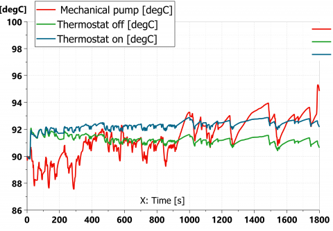
The coolant temperature in the cooling system based on the simulation results is shown in Figure 4.
Figure 4. Coolant temperature
The cooling system for a mechanically-driven pump has an extremely unstable coolant temperature, since the pump speed is directly related to the engine speed, i.e. at partial load and high speeds, the liquid is supercooled and the temperature can fall to 87.5℃, and at low speeds and partial load, the temperature can increase to 95℃. The average coolant temperature for a mechanically-driven pump is 91.4℃, and the average deviation is 1.18℃.
The operation of the cooling system with an electrically-driven pump is the most stable both in temperature and deviations. The average temperature is 91.2℃, and the average deviation is 0.22℃. In general, upward fluctuations do not exceed 1℃. The system responds well to changes in load and releases the required amount of heat in time.
In a system with an electrically-driven pump and a working thermostat, because the thermostat does not fully open and has inertia, the temperature is kept higher by 1.5℃, otherwise, the system responds like a system with an electrically-driven pump.
Based on the simulation results shown in Figure 5, we see that the electrically-driven pump speed is lower across the entire range of the ETC cycle, which means that the pump consumes less energy to transfer the liquid. The average speed of an electrically-driven pump is 742 rpm, with the working thermostat and electrically-driven pump, the speed is 8.2% higher, i.e. 808 rpm, while with a mechanical drive, the average value is 1,285 rpm, which is 42.2% more than that of the electric pump. These data show that the thermostat with an electrically-driven pump negatively affects the energy consumption in the cooling system. The power consumed by electrically-driven pump during the cycle was 1,199 W, while for a mechanically driven pump, it was 4,724 W, so an electrically-driven pump consumes 3.9 times less energy. The electrically-driven pump with a working thermostat consumes 1,294 watts.
Let's analyze the operation of the thermostat itself when working in a transient ETC cycle shown in Figure 6. When operating a mechanically-driven pump, you can see how the thermostat changes the flow section of the channel to the cooling radiator, but when operating an electrically-driven pump, this section changes slightly and the thermostat cannot open fully, thus increasing the resistance and pump speed.
Then, we will examine the operation of the cooling system in the warm-up mode, starting with the ambient temperature-20℃.
Figure 5. Pump speed
Figure 6. Area for opening the thermostat to the radiator
The dynamics of heating the liquid in the cooling system at constant speeds of the mechanically-driven pump 600 rpm corresponding to the idle speed and that of the electrically-driven pump with a minimum speed of 300 rpm is shown in Figure 7.
Figure 7. Dynamics of heating the cooling system
Pay attention to two points here. Firstly, when the thermostat is opening, the temperature in the cooling system with a mechanical drive is 78℃ for about 2,500 seconds, and with an electric drive 70.5℃, then the cold liquid from the radiator is mixed with a small circuit and the temperature growth is slowing down. Secondly, the operating temperature of 91℃ is reached in the electrically-driven system with disabled thermostat in 3,300 seconds, while the temperature of the liquid, when the mechanically-driven pump is operating is 82℃.
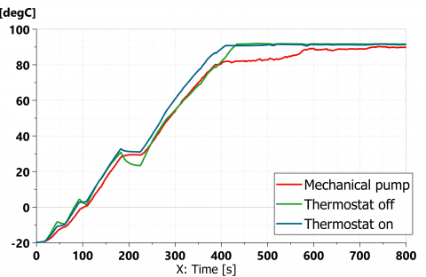
Figure 8. Warming up in a transient ETC cycle
In the transient ETC cycle (Figure 8), the cooling system with an electrically-driven pump takes the same time to warm up as in the system with a mechanically driven pump and a working thermostat. The thermostat is opening in about 400 seconds and the heating of the mechanically driven cooling system is slowing down. In general, during the ETC cycle, warming up is 6 times faster than at idle speed.
Using a non-stationary ETC cycle allows obtaining good results to study of ways to modernize cooling systems for both internal combustion engines and electric transport, as well as in the papers [1-14].
The results of the researches show that the warm-up of the truck engine takes a long time: up to 40℃ about 25 minutes, and up to 90℃ - 45 minutes, and it is more appropriate to use autonomous heaters.
It was also found that using an electric pump without a thermostat slightly increases the warm-up time to 90℃, even though the flows do not divide into a large and small circle, and the liquid circulates through the external radiator. In the ETC cycle, the heating of the cooling system with the working thermostat and the electrically-driven pump is 20 seconds faster (5% of the total warm-up time) than when using an electrically-driven pump with disabled thermostat.
It was found that using a thermostat is unreasonable when the pump is electrically-driven, because the system fails to keep the required temperature and since the thermostat does not open fully, pumping the liquid requires additional energy.
The efficiency of the cooling system can also be increased by using a paddle wheel designed for an electric pump with maximum efficiency at medium speeds [16], or by increasing the efficiency of the cooling system radiator [17, 18].
This study is applicable to trucks, but for passenger cars, data may differ due to the smaller engine volume, the amount of coolant in the system and different transient cycle.
In this paper, a study was carried out to improve the efficiency of the engine cooling system with the transition from a mechanically driven pump to an electrically driven pump. We also investigated two options for modernizing the cooling system with removing the thermostat and leaving the thermostat in the cooling system for faster engine warm-up.
To compare cooling systems in conditions close to real operation, the study was carried out on the basis of the non-stationary cycle of the ETC. The most promising is using an electrically driven pump with the thermostat removed from the cooling system circuit. This saves energy on the pump drive (3.9 times less than the cost of a mechanical drive). The coolant temperature is more stable at sharply changing engine speeds and load: the average deviation is 0.22℃ for the electrically-driven pump and 1.18℃ for mechanically-driven pump. Also, the negative effect of the thermostat on the coolant temperature control when switching to an electrically driven pump was revealed. A system with a working thermostat and an electrically driven pump consumes 7.9% more energy since the thermostat does not open fully, as a result, the pump speed is 8.2% higher. Also, the quality of temperature control is reduced and the deviation from the average value is 0.36℃. Thus, it was revealed that the use of a thermostat in a cooling system with an electric drive pump is undesirable.
This work was supported by the Russian Presidential scholarship for young scientists and postgraduates.
|
U |
heat flow, W |
|
A |
heat exchange area, m2 |
|
$\Delta P$ |
pressure loss, Pa |
|
v |
speed of the coolant, m.s-1 |
|
Q |
volume flow rate, m3.s-1 |
|
Pmech |
mechanical power, W |
|
Greek symbols |
|
|
$\xi$ |
hydraulic resistance coefficient |
|
$\rho$ |
density, kg.m-3 |
[1] Castiglione, T., Bova, S., Belli, M. (2017). A novel approach to the thermal management of internal combustion engines. Energy Procedia, 126: 883-890. http://dx.doi.org/10.1016/j.egypro.2017.08.300
[2] Jeong, S.J., Kim, S., Lee, G., Joung, H., Jeong J. (2017). System-level simulation of active cooling control in an automotive engine through the application of electronically-map-controlled thermostat. Transactions of KSAE, 25(4): 488-497. http://dx.doi.org/10.7467/KSAE.2017.25.4.488
[3] Canova, M., Rostiti, C. (2019). Model order reduction for control of engine thermal management systems using singular perturbation. IFAC-PapersOnLine, 52(5): 604-609. http://dx.doi.org/10.1016/j.ifacol.2019.09.096
[4] Finesso, R., Marello, O., Spessa, E. (2018). Development of a pressure-based technique to control IMEP and MFB50 in a 3.0 L diesel engine. Energy Procedia, 148: 424-430. http://dx.doi.org/10.1016/j.egypro.2018.08.105
[5] Dahl, J., Wassén, H., Santin, O., Herceg, M., Lansky, L., Pekar, J., Pachner, D. (2018). Model predictive control of a diesel engine with turbo compound and exhaust after-treatment constraints. IFAC-PapersOnLine, 51(31): 349-354. http://dx.doi.org/10.1016/j.ifacol.2018.10.072
[6] Doyle, A., Muneer, T. (2019). Energy consumption and modelling of the climate control system in the electric vehicle. Energy Exploration & Exploitation, 37(1): 519-543. http://dx.doi.org/10.1177/0144598718806458
[7] Czerwinski, J., Zimmerli, Y., Mayer, A., D’Urbano, G., Zürcher, D. (2015). Emission reduction with diesel particle filter with SCR coating (SDPF). Emission Control Science and Technology, 1(2): 152-166. http://dx.doi.org/10.1007/s40825-015-0018-7
[8] Mamakos, A., Schwelberger, M., Fierz, M., Giechaskiel, B. (2019). Effect of selective catalytic reduction on exhaust nonvolatile particle emissions of Euro VI heavy-duty compression ignition vehicles. Aerosol Science and Technology, 53(8): 898-910. http://dx.doi.org/10.1080/02786826.2019.1610153
[9] Willems, F., Kupper, F., Rascanu, G., Feru, E. (2015). Integrated energy and emission management for diesel engines with waste heat recovery using dynamic models. Oil & Gas Science and Technology–Revue d’IFP Energies Nouvelles, 70(1): 143-158. http://dx.doi.org/10.2516/ogst/2013210
[10] Sala, R., Krasowski, J., Dzida, J. (2017). The influence of engine warm up phase on nitrogen oxides emission for heavy-duty Euro VI diesel engine. MATEC Web of Conferences, 118: 00035. http://dx.doi.org/10.1051/matecconf/201711800035
[11] Castiglione, T., Perrone, D., Morrone, P., Algieri, A., Bova, S. (2019). Thermal management strategies for CO2 reduction in powertrain systems. AIP Conference Proceedings, 2191(1): 020040. https://doi.org/10.1063/1.5138773
[12] Cortia, E., Abbondanzaa, M., Ravagliolia, V., Taccioli, M. (2018). Control-oriented engine thermal model. Energy Procedia, 148: 766-773. https://doi.org/10.1016/j.egypro.2018.08.134
[13] Lu, L., Chen, H., Hu, Y., Gong, X., Zhao, Z. (2019) Modeling and optimization control for an engine electrified cooling system to minimize fuel consumption. IEEE Access, 7: 72914-72927. http://dx.doi.org/10.1109/ACCESS.2019.2917333
[14] Rymaniak, L. (2017) Comparison of the combustion engine operating parameters and the ecological indicators of an urban bus in dynamic type approval tests and in actual operating conditions. MATEC Web of Conferences, 118: 201711800009. https://doi.org/10.1051/matecconf/201711800009
[15] Siemens PLM Software. Amesim multi pass liq-gas heat exchanger.
[16] DieselNet URL: https://dieselnet.com/standards/cycles/etc.php (date of the application 07.07.2020).
[17] Salakhov, R., Ermakov, A., Gabdulkhakova, E. (2020). Numerical and experimental study of the impeller of a liquid pump of a truck cooling system and the development of a new open-type impeller. Tehnicki Glasnik-Technical Journal, 14(2): 135-142. https://doi.org/10.31803/tg-20200309115417
[18] Mironov, A., Isaev, S., Popov, I., Aksyanov, R., Skrypnik, A. (2020). Improving the efficiency of aircraft heat exchangers. Russian Aeronautics, 63(1): 147-154. http://dx.doi.org/10.3103/S1068799820010213