Huda Ridha* | Mohammed Ghalib Al-Azawy
© 2021 IIETA. This article is published by IIETA and is licensed under the CC BY 4.0 license (http://creativecommons.org/licenses/by/4.0/).
OPEN ACCESS
The fluidized bed and the fluidization process and characteristics were studied in this paper numerically using Computational Fluid Dynamics (CFD) Ansys Fluent 15.0. Constant temperature was applied to both sides of the two-dimensional fluidized bed geometry. The superficial velocity of the working fluid ranged amid (0.08 – 0.5 m/s) and the initial height of the solid particles changed amid (0.05, 0.1, 0.2 m). Aluminum particles and water was used as working materials within the fluidized bed. The model used for the investigations was validated using Ngoh and Lim research results. The results showed that the fluidization head increases as the water inlet superficial velocity increases. As well as when the water inlet superficial velocity increases, the average solid phase temperature increases.
heat transfer, fluidized bed, aluminum particles, Ansys fluent, computational fluid dynamics
The fluid-solid fluidized beds play an important role in the thermochemical applications for their segregation and mixing behavior that affect the efficiency and reaction rate. The fluidized beds segregation and mixing processes is determined by the dynamics of bubble and the characteristics of the flow particles [1]. The process of fluidization involved transforming the solid particles with the aid of liquid or gas flow into semifluid state. A punctured plate was placed at the base of the bed to maintain the solid particles while the fluid flows vertically through the fluidized bed. The purpose from using the punctured plate is to have a flow with even distribution through the bed as well as to support the assembly of the fluidized bed. The bed becomes fluidized when the velocity of the fluid flow reaches a point called the fluidization velocity in this point the entire bed become in semifluid state since the particles break up to single state through the fluid [2]. Several applications use this type of systems some of them are Photo-catalysis, alternative solid fuels combustion, convert natural gas to gasoline using Fischer-Tropsch synthesis, biomass and coal gasification, and kerosene catalytic cracking. The high heat transfer coefficient (HTC) between the bulk of materials and the immersed bodies or walls are one of the supreme important of the fluidized beds. Because of the HTC effectiveness, the fluidized bed used in critical industrial applications such as fluidized bed reactors, combustion, and drying [2]. Recently the computational fluid dynamics (CFD) become an important instrument due to the high development of numerical algorithms and computers which makes it useful in finding the characteristics of flow in fluidized bed dense with solid particles and fluid flow. In the former few decades, several numerical models were established to simulate the flow of mixed solid fluid, the highly used models are Eulerian-Lagrangian and Eulerian-Eulerian models [1]. Bisognin et al. [3] used a combined Experiments Design and CFD techniques to study the heat exchanger of a gas-solid fluidized bed. They investigated the heat transfer coefficient and the variables effected on it. Ansys Fluent model was developed to represent the studied system and it was validated. It was found that the most influences variable on the heat transfer coefficient was the diameter of particles; meanwhile a small influence was found from the solid thermal conductivity and fluid velocity. Tawfik et al. [4] experimentally investigated a swirling fluidized bed reactor, the hydrodynamic parameters of the bed, and the heat transfer of the bed mixture was studied. They used polyethylene (PE) beads (Geldart type- D). It was established that by rising the mass fraction of PE, the minimum velocities for swirling and fluidization rises as well. The heat transfer coefficient decreased by rising the PE beads percentage, while the pressure drop of the bed raised by rising the PE beads amount. Li et al. [5] they studied the thermal and hydrodynamic behavior of a pseudo-2D fluidized bed. The distribution of particle temperature was investigated using a coupled system of a visual camera and a high speed infrared (IR) camera. Jiang et al. [6] built and designed a circular fluidized bed with gas solid flow and heat exchanger spiral plate. They investigated the pressure drop performance and the heat transfer of the flow. They found that the performance of the heat transfer improved by adding particles to the heat exchanger. Over all by adding solid particles, the factor of enhancement raised firstly and then as the solid particles among increase, the enhancement decreased. The rising in the solid particles added lead to increase in the pressure drop of the fluidized bed heat exchanger. Wahyudi et al. [7] investigated the heat transfer and the two-phase flow of fluidized bed fitted with internal pipe. Three-dimensional (3D) model was developed using discrete element method (DEM) and computational fluid dynamics (CFD). It was illustrated that the connection between the surface and fluid and the conduction between the particles and surface results a high heat transfer coefficient. Garcia-Gutierrez et al. [8] investigated using particles of dry ice pelletized in a fluidized bed and its effect on the heat transfer. They found that the mixture of particles and the fluid improved by increasing the fluid velocity. Ehsani et al. [9] experimentally and numerically investigated heat exchanger fluidized bed with liquid - solid mixture. They concluded that an optimum size of particles could increase the rate of heat transfer. Ates et al. [10] studied the fluidized bed combustors and the properties of spectral particle and its effect on radiative the heat transfer. The results illustrated that accurate predictions of radiative heat flux came from assuming gray particle. Lu et al. [11] numerically studied the fluidized bed with gas-solid mixture. The simulation was performed by using methods of coarse-grained particle and discrete element. The numerical results were validated using experimental results data. It was found that the model used could predict the heat transfer accurately and fast taking into the account the fluidized bed scale. Ngoh et al. [12] used computational fluid dynamics to investigate a bubbling fluidized bed with heat transfer. They analyzed vectors distributions of air velocity, vectors of solid velocity, air temperature, solid temperature, and Solid volume fraction, the results of the simulations were compared by using different operating conditions. The data found illustrated that the interfacial surface area effects the heat transfer rate, and it was increased by increasing the bed voidage. Meanwhile by rising the air inlet superficial velocity and reducing the size of particles, the voidage increases. Somjun and Chinsuwan [13] studied the riser fluidized bed-circulating model; the investigation was performed experimentally to study the heat transfer of the system. The results showed that the membrane fin have less cluster solid fractions and heat transfer coefficients compared with the ribbed membrane. In the same manner it was found to be varied with the rib height and spacing. Taofeeq et al. [14] investigated the heat transfer of a fluidized bed and the effect of the pipe diameter on the thermal performance. Several superficial velocities of gas were used as well as the radial positions and axial heights. It was conducted that the increasing in the diameter of the vertical pipe led to increase in the heat transfer coefficient for all the operating conditions that was studied. In this paper, the fluidized bed was studied to show the effect of the applying constant temperature flux to the walls surface of the test pipe. Several superficial velocities were used for the investigation process. The investigation was performed using Ansys fluent Eulerian-Eulerian multiphase model. Aluminum particles was used for the fluidized bed solid particles materials and water was used as the working fluid.
The present work was investigated using Ansys fluentV15. The model of the fluidized bed was generated using Design Modeler V.15 from Ansys Workbench group; with dimensions of (0.0254 × 1.5) m, fluidized bed was modeled. The base of the bed was split to mimic the distributor plate; the (0.0254 m) base length was divided into 8 pieces where the working fluid flows through these pieces. Figure 1 shows the schematic diagram of the fluidized bed model. The mesh was generated with Ansys meshing model, Quadrilateral Dominant method was established as mesh type. In order to assess the requirement of spatial mesh resolution, a grid independency study was performed with 2, 2.5, and 3 mm element sizes. It was found that 2.5 mm element size generates the most suitable results. In the computational domain, mesh was satisfactory to capture the fluid flow properties through the model; Figure 2 presents the mesh of the bed. Aluminum particles and water were used as working materials within the fluidized bed, the details of the numerical model were illustrated in Table 1. The velocity of the working fluid ranged between (0.08 – 0.5 m/s), temperature was applied to the sidewalls of the fluidized bed during the all procedure, see Figure 1. Transient model was set taking the effect of gravity into account. Eulerian-Eulerian multiphase model was set with k-epsilon turbulent model [15]. The Semi Implicit Method for the Pressure Linked Equations (SIMPLE) algorithm for multiphase flow, the discretized governing equations were solved by the finite volume method used for coupling pressure and velocity. A second-order implicit scheme for the discretization process was used for unsteady formulation.
Figure 1. Fluidized bed schematic diagram
Figure 2. Snapshot of the mesh
Table 1. Details of the numerical model
|
Properties |
Value |
|
Packing limit |
0.63 |
|
Particles Diameter |
3 mm |
|
Particles Density |
2719 kg/m3 |
|
Particles specific heat |
871 J/kg.K |
|
Fluid Density |
998.2 kg/m3 |
|
Fluid specific heat |
4182 J/kg.K |
|
Fluid velocity |
0.08, 0.09, 0.1, 0.2, 0.3, 0.4, 0.5 m/s |
|
Bed height initially |
0.05, 0.1, 0.2 m |
|
Mesh size |
2.5 mm |
|
Time step size |
10-3s |
|
Number of time step |
5000 |
2.1 Boundary conditions
Fixed value of temperature was applied to the fluidized bedside walls as the velocity of water changes from 0.08 – 0.5 m/s. the velocity was set normal to the base of the fluidized bed, for each test, the velocity was varied to study the effect of its variation. Two values of initial bed height were set for all the tested water velocities.
2.2 Governing equations
Eulerian multiphase model general equations involve the conservation of momentum and mass.
Momentum conservation equation are as Eq. (1).
$\frac{\partial}{\partial t}\left(\alpha_{q} \rho_{q} \overrightarrow{v_{q}}\right)+\nabla \cdot\left(\alpha_{q} \rho_{q} \overrightarrow{v_{q}} \overrightarrow{v_{q}}\right)=-\alpha_{q} \nabla p+\nabla \cdot {\overline{\overline{\tau }}}_{q}+\alpha_{q} \rho_{q} \vec{g}$
$+\sum_{p=1}^{n}\left(\vec{R}_{p q}+\dot{m}_{p q} \vec{v}_{p q}-\dot{m}_{q p} \vec{v}_{q p}\right)\left(\vec{F}_{q}+\vec{F}_{l i f t, q}+\vec{F}_{v m, q}\right)$ (1)
Mass conservation Equation is as Eq. (2).
$\frac{\partial}{\partial t}\left(\alpha_{q} \rho_{q}\right)+\nabla \cdot\left(\alpha_{q} \rho_{q} \overrightarrow{v_{q}}\right)=\sum_{p=1}^{n}\left(\dot{m}_{p q}-\dot{m}_{q p}\right)+S_{q}$ (2)
where, ${\overline{\overline{\tau }}}_{q}$ is the stress - strain tensor.
${{\overline{\overline{\tau }}}_{q}}={{\alpha }_{q}}{{\mu }_{q}}(\nabla {{\overrightarrow{v}}_{q}}+\nabla {{\overrightarrow{v}}^{T}}_{q})+{{\alpha }_{q}}({{\lambda }_{q}}-\frac{2}{3}{{\mu }_{q}})\nabla .{{\overrightarrow{v}}_{q}}\overline{\overline{I}}$ (3)
where, q represents the phase in all equations.
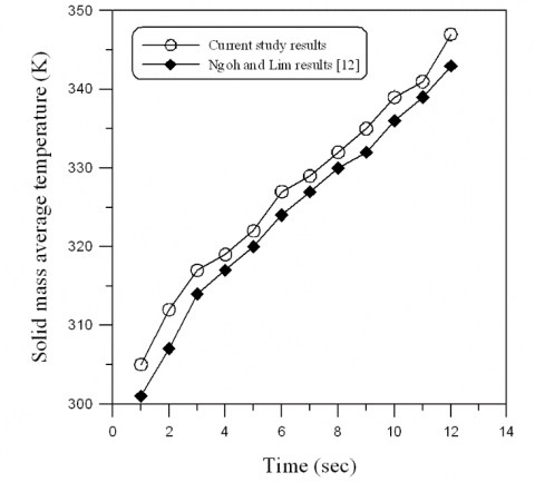
Figure 3. Validation of the model
The simulation results were validated with the work of Ngoh and Lim [12]. Ngoh and Lim [12] used Computational Fluid Dynamics to study the behavior of heat transfer and fluidization. They used diverse range of inlet gas superficial velocity and sizes of particles. The particles size tested was 5 mm. Ansys fluent was used to evaluate the governing equations, using Eulerian-Eulerian model. Figure 3 shows a comparison between the solid mass average temperature computed from this model and the one computed from Ngoh and Lim model, taking the same operating and boundary conditions. The results showed a good agreement with the simulation results of Ngoh and Lim.
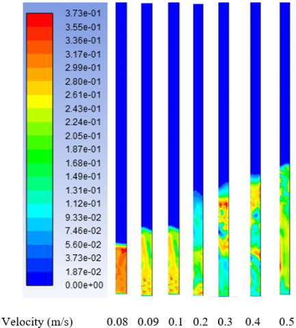
The local structure of the flow was thoroughly studied by analyzing the profile of solid volume fraction as the fluidization degree play an important role in the behavior of heat transfer inside the fluidized bed. The profile of solid phase volume fraction was illustrated in Figures 4-6. It shown clear for the smallest velocities that large bubbles were developed initiating the fluidization process, after five second of physical time it was not yet to grasp the bed top surface. It could be noticed that the profile of solid phase volume fraction demonstrates a non-uniform distribution over a symmetrical distribution. The top denser region was penetrated by the upwards coming particles as it pushed off the wake. Alternatively, as the bubbles exploded at the bed top, the particles were moved up from the wake to the surface. This will improve the process of heat transfer while the hot particles at the walls of the bed were moved around to other places of the bed while the colder particles from the middle dense region descended to the walls. Figures 4-6 shows the head of fluidization as the inlet velocity increases for the same time and wall temperature. As the velocity increases, the head of fluidization increases with respect to the initial particle head.
It was observed from the profile of solid phase volume fraction that a lower concentration of particles is found in the regions close to the walls, demonstrating that the water bubbles as they move up the bed tend to be push to the sides of the bed. It was also illustrated that the water bubbles in the bed higher areas were bigger than the rest of the bed and more radially elongated, meanwhile the water bubbles in the bed lower areas were smaller and radially regularly distributed. This proposed that as water bubbles moved up the bed tended to coalesce.
The fluidization head become steady after it reaches its maximum value as shown in Figure 7, the fluidization time changes from 1 sec to 4 sec and head of fluidization remain constant with changes in the distribution of particles, the pipe with 0 sec was demonstrated in Figure 7 to compare the initial head of particles.
Figure 4. Effect of velocity on the fluidization height with 0.05 m initial particles height
Figure 5. Effect of velocity on the fluidization height with 0.1 m initial particles height
Figure 6. Effect of velocity on the fluidization height with 0.2 m initial particles height
Figure 7. Effect of time on the fluidization height with 0.1 m initial particles height
Figure 8. Particles average temperature with respect to the flow velocity for different initial particles height
The fluidization behavior was investigated further under diverse operating conditions, numerical simulations were carried multiple times with different velocities for inlet water flow while preserving the other material properties and operating parameters constant. Correspondingly, the fluidized bed was heated by a constant on both sides of the two dimensional bed. The initial height of the particles was set three different times (0.05 m, 0.1m, and 0.2 m) while the inlet water superficial velocity, for each simulation was varied between 0.08 m/s to 0.5 m/s. The bed fluidization behavior was modified by rising the water inlet superficial velocity by this change, the behavior of heat transfer in the bed was modified as well. The fluidized bed average solid phase temperature was demonstrated in Figure 8, after five-second physical time of fluidization, the temperature of the particles for higher inlet flow velocity was rising more than the cases for lower inlet flow velocities. Substantial heat transfer was evaluated among the wall, water and solid phases at the borders. Uniform solid phase temperature distribution with no steep temperature gradients designated high conduction or convection heat transfer rates within the solid phase. A strong attachment was evaluated between heat transfer behavior and the fluidization behavior due to the solid phase non-uniform temperature profiles. Moreover, to the transferred heat from water and walls to the particles by conduction and convection, temperature could also be transmitted from high temperature particles to the low temperature particles. A good mixing among solid particles was one of the reasons for the latter; this in turn was strongly reliant on the fluidization behavior. Therefore, when the initial head of particles in the bed was changed, fluidization behavior was changed consequently, and thereby diverse heat transfer behaviors was increased. As the velocity of the bed increases, the solid average temperature increases due to the increase in the turbulent inside the bed, which contribute in the convection and conduction process inside the bed.
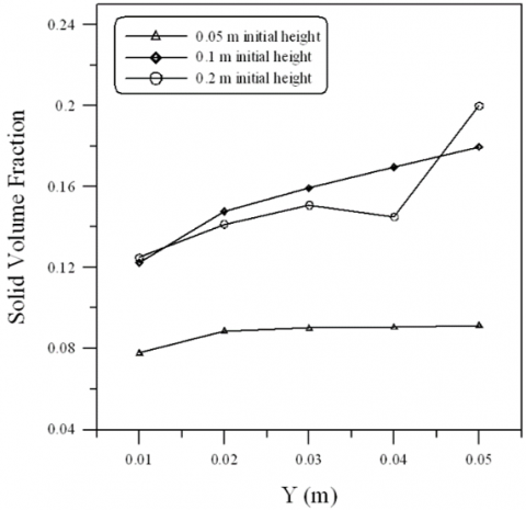
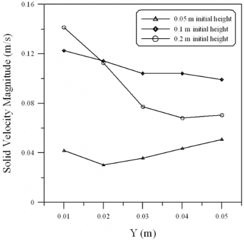
Figure 9a and 9b show the radial profiles of solids volume fraction and velocity magnitude. Note that all the computational data were averaged at 5.0 second. The inlet water velocity for all the data was 0.5 m/s with initial particle height changed from 0.05 m to 0.2 m. an inverse behavior was found in comparison between the solid phase volume fraction and the solid phase velocity magnitude, as the volume fraction of particles decrease its velocity increases. As well as an increasing behavior was illustrated for the volume fraction of solid particles as it goes further away from the bed inlet mean while going further from the bed inlet leads to the solid phase velocity being decreased as its dispersed Throughout the bed.
(a) Solid phase volume fraction
(b) Solid phase velocity magnitude
Figure 9. Solid phase properties at 0.5 m/s inlet water velocity
Fluidized bed with constant temperature applied to the side’s wall was studied numerically. Different ranges of water inlet velocity and bed initial height was studied. Aluminum particles and water were used as working materials within the fluidized bed. It was found that
1- Increasing the inlet velocity leads to increase in the fluidization head with respect to the initial head.
2- Increasing the initial particles head leads to increase in the final fluidization head.
3- Increasing the inlet velocity leads to increase in the temperature of the solid phase.
4- Solid phase volume fraction increases as the flow travel from base to the top of the bed.
5- Solid velocity magnitude decreases as the flow travels from the base to the top of the bed.
|
A |
Volume fraction |
|
B |
dimensionless heat source length |
|
CP |
Specific heat, J. kg-1. K-1 |
|
D |
Diameter (m) |
|
F |
Force (N) |
|
g |
gravitational acceleration, m.s-2 |
|
H |
Height of the fluidized bed |
|
k |
Thermal conductivity, W.m-1. K-1 |
|
Re |
Reynolds number (ρ u D/µ) |
|
T |
Temperature (K) |
|
v |
Velocity (m/s) |
|
w |
Duct width (m) |
|
Greek symbols |
|
|
$\alpha$ |
thermal diffusivity, m2. s-1 |
|
$\beta$ |
thermal expansion coefficient, K-1 |
|
$\phi$ |
solid volume fraction |
|
Ɵ |
dimensionless temperature |
|
µ |
Dynamic viscosity, kg. m-1.s-1 |
[1] Bellan, S., Matsubara, K., Cho, H.S., Gokon, N., Kodama, T. (2018). A CFD-DEM study of hydrodynamics with heat transfer in a gas-solid fluidized bed reactor for solar thermal applications. International Journal of Heat and Mass Transfer, 116: 377-392. https://doi.org/10.1016/j.ijheatmasstransfer.2017.09.015
[2] Fattahi, M., Hosseini, S.H., Ahmadi, G., Parvareh, A. (2019). Numerical simulation of heat transfer coefficient around different immersed bodies in a fluidized bed containing Geldart B particles. International Journal of Heat and Mass Transfer, 141: 353-366. https://doi.org/10.1016/j.ijheatmasstransfer.2019.06.058
[3] Bisognin, P.C., Bastos, J.C.S.C., Meier, H.F., Padoin, N., Soares, C. (2020). Influence of different parameters on the tube-to-bed heat transfer coefficient in a gas-solid fluidized bed heat exchanger. Chemical Engineering and Processing-Process Intensification, 147: 107693. https://doi.org/10.1016/j.cep.2019.107693
[4] Tawfik, M.H.M., Diab, M.R., Abdelmotalib, H.M. (2020). Heat transfer and hydrodynamics of particles mixture in swirling fluidized bed. International Journal of Thermal Sciences, 147: 106134. https://doi.org/10.1016/j.ijthermalsci.2019.106134
[5] Li, Z., Janssen, T.C.E., Buist, K.A., Deen, N. G., van Sint Annaland, M., Kuipers, J.A.M. (2017). Experimental and simulation study of heat transfer in fluidized beds with heat production. Chemical Engineering Journal, 317: 242-257. https://doi.org/10.1016/j.cej.2017.02.055
[6] Jiang, F., Dong, X., Qi, G., Mao, P., Wang, J., Li, X. (2020). Heat-transfer performance and pressure drop in a gas-solid circulating fluidized bed spiral-plate heat exchanger. Applied Thermal Engineering, 171:115091. https://doi.org/10.1016/j.applthermaleng.2020.115091
[7] Wahyudi, H., Chu, K., Yu, A. (2016). 3D particle-scale modeling of gas–solids flow and heat transfer in fluidized beds with an immersed tube. International Journal of Heat and Mass Transfer, 97: 521-537. https://doi.org/10.1016/J.Ijheatmasstransfer.2016.02.038
[8] Garcia-Gutierrez, L.M., Hernández-Jiménez, F., Cano-Pleite, E., Soria-Verdugo, A. (2020). Experimental evaluation of the convection heat transfer coefficient of large particles moving freely in a fluidized bed reactor. International Journal of Heat and Mass Transfer, 153: 119612. https://doi.org/10.1016/j.ijheatmasstransfer.2020.119612
[9] Ehsani, M., Movahedirad, S., Shahhosseini, S. (2016). The effect of particle properties on the heat transfer characteristics of a liquid–solid fluidized bed heat exchanger. International Journal of Thermal Sciences, 102: 111-121. https://doi.org/10.1016/j.ijthermalsci.2015.11.004
[10] Ates, C., Sen, O., Selçuk, N., Kulah, G. (2017). Influence of spectral particle properties on radiative heat transfer in optically thin and thick media of fluidized bed combustors. International Journal of Thermal Sciences, 122: 266-280. https://doi.org/10.1016/j.ijthermalsci.2017.08.023
[11] Lu, L., Morris, A., Li, T., Benyahia, S. (2017). Extension of a coarse grained particle method to simulate heat transfer in fluidized beds. International Journal of Heat and Mass Transfer, 111: 723-735. https://doi.org/10.1016/j.ijheatmasstransfer.2017.04.040
[12] Ngoh, J., Lim, E.W.C. (2016). Effects of particle size and bubbling behavior on heat transfer in gas fluidized beds. Applied Thermal Engineering, 105: 225-242. https://doi.org/10.1016/j.applthermaleng.2016.05.165
[13] Somjun, J., Chinsuwan, A. (2018). Effect of transverse rib on heat transfer between circulating fluidized bed and membrane fins of water wall membrane tubes. Powder Technology, 332: 178-187. https://doi.org/10.1016/j.powtec.2018.03.050
[14] Taofeeq, H., Al-Dahhan, M., Engineering, M.R., Laboratory, A. (2019). Investigation of the effect of vertical immersed tube diameter on heat transfer in a gas-solid fluidized bed. International Journal of Thermal Sciences, 135: 546-558. https://doi.org/10.1016/j.ijthermalsci.2018.10.002
[15] Al-Turaihi, R.S., Oleiwi, S.H. (2015). Experimental and CFD investigation the effect of solid particle height in water-solid flow in fluidized bed column. International Journal of Mechanical Engineering and Applications, 3(3): 37-45. https://doi.org/10.11648/j.ijmea.20150303.12