Seyedeh Mobina Mirshafiee | Elham Omidbakhsh Amiri*
© 2021 IIETA. This article is published by IIETA and is licensed under the CC BY 4.0 license (http://creativecommons.org/licenses/by/4.0/).
OPEN ACCESS
In this work, the heat transfer was investigated in a rectangular channel with an internal triangular obstacle and square baffles. Three square baffles were located on the lower wall of the channel, while a triangular obstacle was placed in the middle of the channel and placed before the first baffle. Air was used as a working fluid. The governing equations were solved with finite volume method. The effect of the geometric parameters such as the ratio of the width to height of the obstacle, the vertical and horizontal distance between obstacle and baffle and the baffle angle, has been investigated on the heat transfer in this system. Then, in next parts, the effect of baffle and obstacle shape was considered. The results show that by increasing the width and height of the obstacle, the baffle temperature decreases and the Nusselt number of the baffle increases. In fact, when the obstacle width becomes larger, a longer vortex is formed that helps to improve the heat transfer rate. Also, when the obstacle is perpendicular to the flow path, better heat exchange between the baffle and the fluid was performed. With Elliptical baffles and a triangular obstacle, higher heat transfer was achieved.
computational fluid dynamic, Nusselt number, square baffle, rectangular channel, triangular obstacle
Fluid flow and heat transfer studies in many devices can help to a better understanding their performance. For example, it can help to improve the performance of compact heat exchanger. For increasing the heat transfer rate, there are different methods, such as adding nanoparticle to a base fluid (nano-fluid) [1], surface machining, inserting baffle (or obstacle) in the flow path [2, 3]. Increasing the baffle (or obstacle) in the flow path causes turbulence and helps to heat transfer. In some equipment such as electronic devices, raising the temperature is unacceptable. With these baffles, cooling the system can be improved. These baffles are placed in different locations, such as on the upper (or lower) wall of the channel, (usually said as a block) or in the channel, above or around of blocks (named as an obstacle). In this study, we focus on the obstacles. Different shapes were used in different studies for obstacles in the channels such as rectangle, triangle, and cylinder. In this part, some of them will be reviewed. First of them is a system with a triangular obstacle. Oztop et al. [3] considered the heat transfer and fluid flow in a channel with rectangular blocks on the upper wall of the channel and a triangular bar above the first block. The governing equations were solved using a commercial CFD package FLUENT. Different positions for the triangular bar were investigated. Results show with increasing the Reynolds number, the thinner thermal boundary layer was achieved. From streamlines, it can be found that there are two circulation cells at the rear of the bar. The big vortex is situated near the bottom edge of the triangle. Also, the variation of the local Nusselt number on each surface of the blocks was considered for three different locations of a bar.
In another work, Herman and Kang [4] studied heat transfer in a grooved channel. In their channel, a curved obstacle was placed on the heated block. In their experimental work, the air was used as the working fluid in a wind tunnel. The temperatures of the channel and heated blocks are measured. Also, the channel pressure drop was evaluated. Then, the ratio of the mean Nusselt number and the friction factor was used for investigating the performance of the grooved channels. Results show an increase in heat transfer by a factor of 1.5-3.5, when compared to the basic grooved channel, the pressure drop is 3-5 times higher than in the basic grooved channel. Also, Lorenzini-Gutierrez et al. [5] studied the heat transfer in a grooved channel with curved flow deflectors, experimentally and numerically. They used a horizontal channel formed by parallel plates with ten rectangular heaters along its length. At the end of each heater, a deflector (as a quarter of a tube with radius A and it is initially centered on the right edge of the heater block) was placed. In the numerical simulation section, the two-dimensional model was employed for the simulation of the heat transfer problem. The computational fluid dynamics was applied to solve the governing equations through the finite volume method numerically. In the experimental section, a set of ten rectangular aluminum block heaters with specific dimensions and the deflectors was studied. The deflectors were made from nylon tube sections and connected altogether through an acrylic piece. They studied the effect of the geometric parameters on the hydrodynamic and thermal behavior. They showed the velocity fields between two blocks for two different geometric configurations operating at specific Reynolds number. Also, they investigated the multifactor effect (some parameters of geometry and Nusselt number and pressure drop) in the different systems. In fact, the single variation of each factor and the interaction between factors were considered on both the thermal and hydrodynamic viewpoints. From results, it can be found that there's no interaction between the four factors for the hydrodynamic response. Therefore, the single variation of each factor has a stronger influence on this result. Also, results show the horizontal displacement of the deflector presents interaction with the other factors due to the intersection between behavior curves. Nevertheless, this interaction may be neglected because the variation of this factor is not representative in the change in pressure drop. Therefore, the effects on the average Nusselt number may be regarded as independent. Another work with a cylindrical obstacle is Fu and Tong’s work [6]. They numerically investigated the heat transfer and flow pass in a channel. The rectangular blocks with an oscillating cylinder were used. The oscillating cylinder and the flow affect each other, and the variations of the flow field become time-dependent, so, a moving boundary problem is presented. The governing equations are solved with the finite element method and Lagrangian-Eulerian approach. The variations of streamlines around the cylinder and the Nusselt number were considered. Some other studies with curved or cylindrical obstacles can be found in Refs. [7-9].
Another used shape is rectangular obstacles. Perng and Wu [10] numerically studied unsteady turbulent flow in a channel with heated rectangular blocks. A rectangular obstacle (named as turbulator) was placed above the first block. Large Eddy Simulation (LES) was used for solving the governing equations. They studied the flow pass and heat transfer enhancement with and without turbulator. Also, the effect of turbulator geometry was considered. Results show that the system with a rectangular turbulator can effectively improve the turbulent heat transfer. When Gr/Re2 equals to 20, there is the buoyancy effect along the vertical surfaces of the blocks. Some other works with a rectangular obstacle were studied [11-13].
In the present work, a three-dimensional model was considered for heat transfer in a rectangular channel with three square baffles on the lower channel wall and a triangular obstacle before the first baffle. Governing equations were solved based on the finite volume model. The effect of geometry parameters such as the ratio of the width to height of the obstacle, the vertical and horizontal distance between obstacle and baffle, and the baffle angle, was investigated on the heat transfer in this system. Also, the effect of obstacle shape was considered, when the square baffles were used on the lower channel wall. And in the next part, when a triangular obstacle was used in a channel, the effect of baffle shape was investigated.
A rectangular channel with three square baffles on the lower wall was considered as a base model in this work (adapted from the paper [3]). A triangular obstacle was placed in the middle of the channel and placed before the first baffle. Figure 1 shows a schematic view (2d and 3d views) of the base model. The channel length (L) and width (H) are 62.5 cm and 5 cm, respectively. The distance between two baffles equals to 2 cm. Table 1 listed the geometry parameters.
This base model was considered based on three viewpoints. The effect of the location and the dimensions of a triangular obstacle (Figure 2), the effect of middle obstacle shape (Figure 3) and the effect of baffle shape (Figure 4).
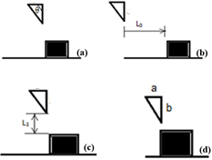
For considering of the effect of obstacle location, horizontal and vertical distances between obstacle and baffle were studied. Also, the ratio of width to height of obstacle and the angle of triangular obstacle were investigated (Figure 2).
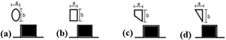
In the next part, the shapes of baffle or obstacle were investigated. When the square baffle was used in the model, with changing the obstacle shape to trapezoidal, rectangular and elliptical obstacle, the effect of obstacle shape was studied (Figure 3). For considering the effect of baffle shape, trapezoidal and elliptical baffles were studied (Figure 4).
Table 1. Geometry parameters
|
Parameter |
Value (cm) |
|
a |
0.5 |
|
b |
1 |
|
d |
2 |
|
y |
3.5 |
Figure 1. (a) 2d view, (b) 3d view of base model
Figure 2. (a) Obstacle angle, θ, (b) Horizontal distance, L0, (c), Vertical distance, L1 (d) Dimensions of obstacle, a, b
Figure 3. (a) Elliptical obstacle, (b) Rectangular obstacle, (c) Trapezoidal obstacle, (d)Triangular obstacle
Figure 4. (a) Elliptical baffle, (b) Trapezoidal baffle, (c) Rectangular baffle
3.1 Governing equations
Three dimensional governing equations consist of continuity, momentum and energy equations (Eqns. (1)-(3)).
$\nabla \cdot \rho \vec{V}=0$ (1)
$\rho(\vec{V} . \nabla \vec{V})=-\nabla p+\mu \nabla^{2} \vec{V}$ (2)
$\vec{V} \cdot \nabla \vec{T}=\alpha \nabla^{2} \vec{T}$ (3)
where, $\alpha$ is defined as $\alpha=\mathrm{k} / \rho \mathrm{Cp}$. Also, $\rho, \vec{V}, \mathrm{p}, \mathrm{T}$ are density, velocity vector, pressure and temperature, respectively. Air is a working fluid and its density $(\rho)$, heat capacity (Cp), thermal conductivity (k) and viscosity $(\mu)$ are defined as Eqns. (4)-(7) [14] Because the channel is horizontal, the gravity force is neglected.
$\rho=358 \cdot 517 \times T^{-1 \cdot 00212}$ (4)
$C p=7 \cdot 875 \times 10^{-6} \cdot T^{2}+0 \cdot 1712 \cdot T+949 \cdot 72$ (5)
$k=-1 \cdot 3707 \times 10^{-8} \cdot T^{2}+7.616 \times 10^{-5} \cdot T$$+4.5968 \times 10^{-3}$ (6)
$\mu=-8.3123 \times 10^{-12} \cdot T^{2}+4.4156 \times 10^{-8} \cdot T$$+6.2299 \times 10^{-6}$ (7)
3.2 Boundary conditions
In this work, the no-slip condition was used for upper and lower walls of the channel, baffles and obstacle walls. There is the specific heat flux (6500 W/m2) on the baffle walls. The obstacle wall is adiabatic. The constant temperature (300K) is established on the upper and lower walls of the channel. Air flow with constant temperature (300 k) and velocity (Re=475) enters in the inlet section.
3.3 Numerical simulation
Partial differential equations of governing equations were solved based on the finite volume method [15] over the control volume. The second-order upwind discretization scheme is used for governing equations except for the pressure. The simple algorithm is employed to solve the convection-diffusion equations. The convergence criteria are 10-6 for all parameters except of for energy (10-7). The Hex grids with a mesh size of 0.2 were used for models. Figure 5 shows the grid of the base model. Grid independency analysis was conducted to ensure that the resolution of the mesh was not influencing the results. Figure 6 shows the effect of grid number on the Nusselt number (Nu) of the upper wall of channel (for the base model as an example).
Figure 5. Used grid for the base model
Figure 6. Effect of Grid number on Nusselt number of the upper wall of the channel
For considering of the results, two viewpoints were accounted: heat transfer (with Nu and Tb (baffle temperature) and fluid mechanic (friction coefficient, f). Nusselt number on the baffle was calculated as Eq. (8) with convective heat transfer coefficient (h). Also, Eq. (9) was used for calculation friction coefficient [16].
$N u=\frac{h H}{k}$ (8)
$f=\frac{\frac{\Delta p}{l} D_{h}}{0.5 \rho u_{m}^{2}}$ (9)
3.4 Validation of the model
For validation of this work, Oztop’s study [3] was accounted. In their work, a rectangular channel with a triangular obstacle in the middle channel and square baffles on the lower wall was considered. Figure 7 shows the effect of the Nusselt number on the channel length with our simulation (solid line) and their work (dash line). The average error is less than 10%, it can be said there is a good agreement between data.
Figure 7. Validation of our results with Oztop’s study [3]
4.1 Effect of geometry parameters
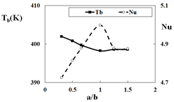
In this section, three parameters were considered: the ratio of width to height of the triangular obstacle, the distance between the baffle and obstacle, the angle of the triangular obstacle. Figure 8 shows the variation of the Nusselt number and baffle temperature versus the ratio of width to height of the triangular obstacle (a/b). This data classified into two parts: less than one and higher than one. For data with less than one, the obstacle height is constant and, its width is varied. While, for data with higher than one, the width is constant, and its height is varied.
From the first part of the data, results show with increasing the obstacle width, baffle temperature decreases, while the obstacle height is constant. Considering the vertex in the front of the obstacle, it can be found longer vertex is formed with increasing the obstacle width. Longer vertex helps to better heat transfer. In the second section of data, with decreasing the obstacle height, baffle temperature increases, and the Nusselt number decreases. With the lower height of the baffle, the vertex in the front of the obstacle is smaller. So, lower heat transfer and higher baffle temperature were achieved.
Cooling the blocks is a goal for these devices. So, the lower baffle temperature is desirable. On the other hand, with increasing the Nusselt number (results in increasing convective heat transfer coefficient) and with constant heat flux on the baffle wall, the difference between the baffle and fluid temperature decreases, and the results means the baffle becomes cool. So, in conclusion, decreasing of baffle temperature and increasing the Nusselt number are desirable. So, a higher height and width of the obstacle is desirable for better heat transfer.
The distance between baffle and obstacle is the second parameter considered in this section. The vertical and horizontal distance between baffle and obstacle are named as L1 and L0, respectively. In this section, the dimensions of the baffle and obstacle are the same as the base model.
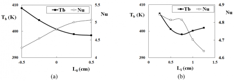
Figure 9(a) shows the variation of the Nusselt number and baffle temperature versus L0. In base mode, L0=0. Two directions (before and after this location) were considered. It can be found with increasing this distance, the baffle temperature decreases, and the Nusselt number increases. Figure 9(b) shows the variation of the Nusselt number and baffle temperature versus L1. With increasing L1, initially, baffle temperature decreases and then slowly increases. With L1=0.75, the minimum temperature is achieved. With increasing this distance (L1), in fact, the space between obstacle and first baffle increases. This space can be affected on the vertex generated in front of the obstacle. Maybe, this vertex doesn’t form in the larger distance.
Figure 8. Effect of the ratio of a/b on the baffle temperature and Nusselt number
Figure 9. Effect of the (a) Horizontal and (b) Vertical distance between baffle and obstacle on the baffle temperature and Nusselt number
Figure 10. Effect of the obstacle angle on the (a) baffle temperature and (b) Nusselt number
In the base model, the triangular obstacle was vertically placed in the flow path (the angle (θ) equals to 90 degree). In this part, two other different angles (30 and 60 degree) were considered. Figure 10 shows this result on the baffle temperature and the Nusselt number. Results show with 90 degree, the baffle temperature is lower than the other one. Also, the Nusselt number with 90 degree is much higher. So, a triangular obstacle with 90 degree has better performance.
4.2 Effect of obstacle shape
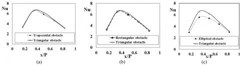
In the base model, a triangular obstacle was used in the middle of the channel. In this section, with changing the obstacle shape, this effect on the heat transfer performance was considered. Other three shapes were accounted for: Elliptical, Rectangular, and Trapezoidal obstacles. For all cases in this section, square baffles were placed on the upper wall of channels. Figures 11 and 12 compare the baffle temperature and the Nusselt number of each one respect to the triangular obstacle. In the horizontal axis, the length of each section of the baffle is divided to the perimeter to achieving a non-dimensional parameter. From Figure 11(a) and (b), it can be found there isn’t a clear difference between the baffle temperature of a Trapezoidal (or Rectangular) obstacle and the Triangular obstacle. The same behavior was seen for the Nusselt number (Figure 12(a) and (b)).
On the other hand, Figure 11(c) shows the baffle temperature with the Elliptical obstacle is higher than the Triangular obstacle. And also, the Nusselt number with Elliptical obstacle is lower than the Triangular obstacle (Figure 12(c)). So, with the Elliptical obstacle, less cooling of the baffle is achieved. So, a triangular obstacle presents better heat transfer performance.
Figure 13 shows the streamlines of these systems. It can be seen the vertex in front of the triangular obstacle is larger than other shapes. Larger vertex helps to better mixing and so better heat transfer.
Figure 11. Effect of the obstacle shape on the baffle temperature
Figure 12. Effect of the obstacle shape on the Nusselt number
Figure 13. Stream lines in different systems with different obstacle shapes
The friction factor in these systems with different obstacle shapes was considered in the next step. In Figure 14, it can be seen, the system with triangular obstacle presented higher friction factor respect to other shapes. Sharper corners of the triangle structure cause a higher pressure drop, so more friction factor is presented.
Figure 14. Effect of the obstacle shape on the friction factor
In the previous studies [10] for better understanding of the performance of these systems, the thermal performance coefficient is defined as Eq. (10). System with higher thermal performance coefficient shows better performance.
$\beta=\frac{\left(\frac{N u}{N u_{0}}\right)}{\left(\frac{f}{f_{0}}\right)^{\frac{1}{3}}}$ (10)
Subscript 0 represents the base model (with a triangular obstacle), so the thermal performance coefficient (β) for the base model equals to one. When this formula was applied for the system with the Elliptical obstacle, it can be found the value of the thermal performance coefficient was less than one (=0.91), so, the better performance was achieved by the system with a triangular obstacle.
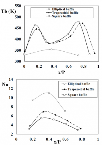
4.3 Effect of baffle shape
Figure 15. Effect of the baffle shape on the baffle temperature and Nusselt number
Figure 16. Effect of the baffle shape on the friction factor
In this section, the square baffles in the base model, were changed to Elliptical and Trapezoidal baffles, while the triangular obstacle was used for all these models. Figure 15 compares the baffle temperature and the Nusselt number of each other. Results show the baffle temperature in the system with Elliptical baffles is lower than other shapes. Also, the Nusselt number in this system is much higher than other shapes. So, the system with Elliptical baffles presents better heat transfer. On the other hand, Figure 16 shows the system with Elliptical baffles has a lower friction factor. So, the system with Elliptical baffles has better performance.
The heat transfer was numerically investigated in a rectangular channel with three square baffles and a triangular obstacle. Effect of other shapes of obstacle and baffle was considered. According to the modeling results, following conclusions have been made:
|
a |
Obstacle width, cm |
|
|
b |
Obstacle height, cm |
|
|
Cp |
Heat capacity, J/kg.K |
|
|
d |
Baffle width, cm |
|
|
DH |
Hydrolic Diameter, m |
|
|
Gr |
Grashof number |
|
|
h |
Convection heat transfer coefficient, W/m2.K |
|
|
H |
Channel width, cm |
|
|
k L |
Thermal conductivity coefficient, W/m.K Channel length, cm |
|
|
L0 |
Horizontal distance between baffle and obstacle, cm |
|
|
L1 |
Vertical distance between baffle and obstacle, cm |
|
|
Nu |
Nusselt number |
|
|
P |
Pressure, Pa |
|
|
Re |
Reynolds number |
|
|
T |
Temperature (K) |
|
|
V |
Velocity, ms-1 |
|
|
W |
Distance between two baffles, cm |
|
|
Greek symbols |
||
|
a |
Thermal diffusivity, m2s-1 |
|
|
β |
Thermal performance coefficient |
|
|
θ |
Obstacle angle, degree |
|
|
µ |
Dynamic Viscosity, kg/m.s |
|
|
ρ |
Density, kgm-3 |
|
[1] Sajid, M.U., Muhammad Ali, H. (2019). Recent advances in application of nanofluids in heat transfer devices: A critical review. Renewable and Sustainable Energy Reviews, 103: 556-592. https://doi.org/10.1016/j.rser.2018.12.057
[2] Korichi, A., Oufer, L. (2007). Heat transfer enhancement in oscillatory flow in channel with periodically upper and lower walls mounted obstacles. International Journal of Heat and Fluid Flow, 28: 1003-1012. https://doi.org/10.1016/j.ijheatfluidflow.2006.11.002
[3] Oztop, H.F., Varol, Y., Alnak D.E. (2009). Control of heat transfer and fluid flow using a triangular bar in heated blocks located in a channel. International Communications in Heat and Mass Transfer, 36: 878-885. https://doi.org/10.1016/j.icheatmasstransfer.2009.05.006
[4] Herman, C., Kang, E. (2002). Heat transfer enhancement in a grooved channel with curved vanes. International Journal of Heat and Mass Transfer, 45: 3741-3757. https://doi.org/10.1016/S0017-9310(02)00092-3
[5] Lorenzini-Gutierrez, D., Hernandez-Guerrero, A., Luis Luviano-Ortiz, J., Leon-Conejo J.C. (2015). Numerical and experimental analysis of heat transfer enhancement in a grooved channel with curved flow deflectors. Applied Thermal Engineering, 75: 800-808. https://doi.org/10.1016/j.applthermaleng.2014.10.002
[6] Fu, W.S., Tong, B.H. (2004). Numerical investigation of heat transfer characteristics of the heated blocks in the channel with a transversely oscillating cylinder. International Journal of Heat and Mass Transfer, 47: 341-351. https://doi.org/10.1016/S0017-9310(03)00303-X
[7] Luviano-Ortiz, L., Hernandez-Guerrero, A., Rubio-Arana, C., Romero-Mendez, R. (2008). Heat transfer enhancement in a horizontal channel by the addition of curved deflectors. International Journal of Heat and Mass Transfer, 51: 3972-3984. https://doi.org/10.1016/j.ijheatmasstransfer.2007.12.020
[8] Yang, Y.T., Chen, C.H. (2008). Numerical simulation of turbulent fluid flow and heat transfer characteristics of heated blocks in the channel with an oscillating cylinder. International Journal of Heat and Mass Transfer, 51: 1603-1612. https://doi.org/10.1016/j.ijheatmasstransfer.2007.07.010
[9] Selimefendigil, F., Öztop, H.F. (2014). Numerical study and identification of cooling of heated blocks in pulsating channel flow with a rotating cylinder. International Journal of Thermal Sciences, 79: 132-145. https://doi.org/10.1016/j.ijthermalsci.2014.01.010
[10] Perng, S.W., Wu, H.W. (2008). Numerical investigation of mixed convective heat transfer for unsteady turbulent flow over heated blocks in a horizontal channel. International Journal of Thermal Sciences, 47: 620-632. https://doi.org/10.1016/j.ijthermalsci.2007.04.003
[11] Wu, H.W., Perng, S.W. (1999). Effect of an oblique plate on the heat transfer enhancement of mixed convection over heated blocks in a horizontal channel. International Journal of Heat and Mass Transfer, 42: 1217-1235. https://doi.org/10.1016/S0017-9310(98)00247-6
[12] Perng, S.W., Wu, H.W., Jue, T.H. (2014). Heat transfer augmentation and vortex-induced vibration in a block-heated channel. International Journal of Thermal Sciences, 79: 18-33. https://doi.org/10.1016/j.ijthermalsci.2013.12.004
[13] Perng, S.W., Wu, H.W., Jue, T.H. (2012). Numerical investigation of heat transfer enhancement on a porous vortex-generator applied to a block-heated channel. International Journal of Heat and Mass Transfer, 55: 3121-3137. https://doi.org/10.1016/j.ijheatmasstransfer.2012.02.037
[14] https://www. neutrium.net/properties/properties-of-air.
[15] Versteeg, H.K. Malalasekera, W. (1995). Introduction to Computational Fluid Dynamics the Finite Volume Method, Longman, England.
[16] Nagarajan, V., Chen, Y., Wang, Q., Ma, T. (2014). Hydraulic and thermal performances of a novel configuration of high temperature ceramic plate-fin heat exchanger. Applied Energy, 113: 589-602. https://doi.org/10.1016/j.apenergy.2013.07.037