Abdul Aabid | Sher Afghan Khan*
© 2021 IIETA. This article is published by IIETA and is licensed under the CC BY 4.0 license (http://creativecommons.org/licenses/by/4.0/).
OPEN ACCESS
This article focuses on the flow development and the static wall pressure distribution along the circular duct from the convergent-divergent (CD) nozzle. The study aims to examine the quality of the stream in the conduit when the control is employed. The microjets are activated at the base at (PCD) of 13 mm, and the diameter of the microjets is 1 mm. Mach numbers of the investigation are 1.3, 1.9, and 2.4. The length of the duct considered was from L = 10D to 1D. The diameter of the enlarged tube was 16 mm. The experiments were conducted for NPRs from 3 to 11. The results revealed that the lowest duct length mandatory for the flow continued to attach with the circular duct wall are L/D = 1, 2, and 3 for Mach numbers 1.3, 1.9, and 2.4, respectively. The investigation outcome indicates that there are mild oscillations in the flow-field for correctly expanded flows. The oscillatory trend has a pronounced impact on the duct's flow when the jets are operated at higher NPRs. The control does not adversely affect the flow field, and the magnitude of wall pressure is nearly similar.
nozzle, wall pressure, duct, nozzle pressure ratio, Mach number
Sudden expansion is a common occurrence in the aerospace and automobile industries. Whenever the shear layer encounters a sudden increase in the area, it results in flow separation and reattachment. This separation of the shear layer results in a recirculation zone where the base pressure is low, resulting in a considerable drag. The base drag can be as high as seventy percent of the total drag. Hence there is a need to control this component of the drag. Therefore, by controlling the base pressure, we can increase the range of the aerospace vehicles. They are increasing their range/kill capacity, finally resulting in energy savings. As humans exploit natural resources very soon, and natural resources will be exhausted. The excessive use of fossil fuels has resulted in air pollution, global warming, and the ozone layer's depletion. Hence, there is a need to conserve energy and fossil fuels. The problem of sudden expansion happens in internal as well as external flow. A similar flow situation is seen in a backward-facing step. In all these circumstances, the flow separates and re-attaches with the wall resulting in low base pressure, sub-atmospheric pressure. This small base pressure results in a base drag that contributes significantly and has a significant role in terms of base drag influencing the aerodynamic vehicles' total drag force affecting the overall range of the rockets/missiles and the aircraft.
While scanning the literature, it is found that this low base pressure and the resulting base drag contribute significantly, and thus there is a need to control this component of the drag. The drag due to the viscous effects will be there by default due to the mission requirements, and the minimum wave drag will be present despite the high L/D ratio at sonic and supersonic Mach numbers. Based on these circumstances, numerous studies have been reported on base pressure control using different active and passive methods, which is reviewed in the literature section of this article, which depends on the end-users and applications' requirement.
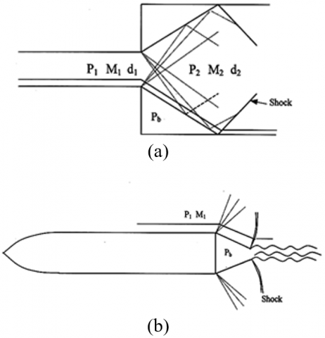
A critical situation is found in the external flow past a projectile or missile in the flight whose base is blunt or similar, to a backward-facing step where the flow becomes inward at the expansion point. The flow stream is outward at the nozzle's exit for internal flow before being exhausted to the enlarged duct (Figure 1a). An experimental study with sudden expansion has many benefits as compare to the external flow. The amount of air needed to conduct the experiments is decreased significantly. For the external flow case (Figure 1b), the test section's cross-section area is large to accommodate the model. Also, wall intervention will not disrupt the flow of the test model. The mass flow rate requirement becomes too large to manage in an external flow; hence, this study is conducted using an internal flow approach. We can measure the temperature and the static wall pressure in internal flow, which is an added advantage.
The results obtained from external and internal flows are closely related to each other. Due to the advantages of conducting experiments with internal flows over external flows, most of the investigations are carried out with internal flows, and the results can be applied to the external flows. In the present study also, we are conducting experiments with internal flows. In Figure 2 the sudden expansion flow field of internal flows is shown. Figure 2 shows that the flow separates at the corners and re-attaches at point O. This point is called the reattachment point, and the length AO (as shown in the figure) is called reattachment length. At the corners, an expansion fan is formed. At the reattachment point, a shock is included in the case of supersonic flows. The base corner is assumed of like a sump with two deliveries of mass. One is due to viscous and frictional effects. And the next is due to the backflow. Because of this inflow and outflow of the base region's mass, a wake is formed, resulting in its low-pressure area.
Figure 1. A view of (a) Internal flow (b) External flow
Figure 2. A view of the sudden expansion flow
The factors which affect the base pressure and the flow field in the duct can be listed as follows,
Pb = f(AR;L/D;M; P0; l/d; δ;BL type) (1)
where, Pb is base Pressure, P0 is the atmospheric pressure, AR = (D/d)2 = area ratio, D = diameter of the duct, d = exit nozzle diameter, δ = is thickness Boundary Layer, M = is the Mach number at the upstream corner, and P0 = is the settling chamber stagnation pressure
The authors reported the active control of base pressure with sudden expansion [1-9]. All the studies either showed a parameter's effect by varying the NPR, Mach number, duct length, and area ratio. The motivation of the parametric study is to obtain base pressure control. Whenever the control mechanism is employed, either passive or active, it is mandatory on the part of the researcher to monitor the static pressure at the duct surface and flow field in a suddenly expanded duct. The wall pressure distribution has been reported for different Mach numbers [10-14]. The primary observation of wall pressure is based on the Mach number variation and area ratio in their reviews. The results are obtained for the different NPR's and the duct lengths. The studies have also been found for a nozzle. They focused on the laminar and turbulent boundary layer flows for a cylinder with the suction [15], and the noise created [16]. The passive methods can also control the flow in the suddenly expanded duct. The authors [17, 18] studied the effect of static cylinders, as well as dynamic cylinders, have been used by the authors [19-22], and multiple cavities [23] are used to control the flow. As passive control ribs have also been employed within the recirculation zone of a square duct [24], and the resulting base pressure and the wall pressure were measured [25, 26].
Mbuyamba [27] used the ANSYS fluent in obtaining the exact design of the supersonic nozzle in which they were using the cold gas for investigation. In a De-Laval nozzle, the pressure and velocity were obtained using the numerical and theoretical method [28]. Later, they validated the numerical results obtained through the ANSYS simulation and compared them with the wind tunnel data. Patel [29] identified the flow-field and optimization of parameters for a high-speed supersonic nozzle to apply the flow accelerating devices in the rocket engine at the C-D's various divergence angle nozzle. In an age of increasing space-related exploration and application in industries, the implementation of more efficient and high-performing rocket engines is essential [30]. Belega and Nguyen [31] examined flow through the nozzle using finite volume code ANSYS Fluent 6.3.
The simulation of the flow using ANSYS fluent by utilizing the K-ε and K-w turbulent models for the pressure-based problem reported by the authors [32-35]. In some cases, the authors show the importance of area ratio and obtained the results using the numerical approach for the different area ratio [36]. Pathan et al. [37] investigated the base pressure deviations in a suddenly expanded flow with a density-based model and compared the behavior of flow in an internal and external flow. Pathan et al. [38] determined the effect of NPR on the base region's pressure and the location where the flow re-attached with the duct wall and investigated base pressure control [39]. Pathan et al. [40] established the influence of NPR and control jets position as controller of base pressure with sudden expansion from a CD nozzle. Using K-ε turbulent modeling, several studies have been reported [35, 41-47] in the flow field through a CD nozzle. In their studies, simulations were done at different Mach numbers and area ratios. The authors studied the flow from the nozzles and obtained results based on various area ratios and the duct lengths. The various turbulence models were used for the simulation for a wedge [48, 49], splitter plate [50], non-circular cylinder [51, 52], and airfoil [53] in the previous work.
In the previous studies of a numerical and experimental approach, the determination of parametric effects could be a long process in a study. Therefore, the innovative method design has also been implemented for the problem of control of base pressure. In this case, the research has been found whether they used full factorial design or Taguchi design. For these cases, the experiments or numerical approach needs to obtain the selected parameters' input results. Later, these results are used for further optimization study. The authors [54-58] have used the design of experiments method in their research; they obtained results for different parameters and dimensions using the design of experiments. Furthermore, the authors show the predictions and most suitable settings for the optimum solution to control the base pressure. Several studies have been found in this field, which was used to explore microjet as a control mechanism for base pressure. This study aims to assess the control mechanism's influence on the flow development in the enlarged duct at Mach numbers of 1.3, 1.9, and 2.4 for area ratio 2.56.
A CD nozzle attached with a suddenly expanded duct and its critical features of the flow is shown in Figure 2 shows that the flow from the CD nozzle is under-expanded. At the nozzle exit, there an expansion fan through which the flow will expand. The flow gets re-attached with the wall of the duct. Later in the downstream, there is regrowth of the boundary layer.
Figure 3 shows the nozzle and enlarged duct used for the present study. Along the wall of the enlarged duct, pressure taps are provided to scan the wall pressure field. Figure 4 shows the free jet facility in which the model loaded on the setup. A mercury manometer is shown, which was used for measuring wall pressure distribution. Figure 5 shows another view of the free jet facility. In this view, the pressure regulating valve (PRV) is shown, which controls the NPR. Figures 6 and 7 show a picture of the storage tank, pressure transducer.
Figure 3. Nozzle and duct assembly
Figure 4. Jet facility with the control chamber and multi-tube manometer
Figure 5. A view of the free jet facility
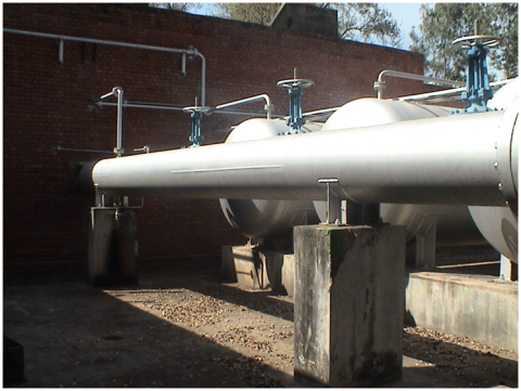
Figure 6. A picture of the storage tank
Figure 7. Pressure Transducer
Figure 8. A view experimental setup
Figure 8 shows the schematic diagram of the experimental setup used for the present study is similar to Ref. [2]. The pressure transducer used has 16 channels, and the pressure range is 0-15 bar; they measure pressure at the base. The pressure transducer records three-fifty samples per second and shows the averages reading on the monitor, and, at the same time, writes the average values on the hard disk of the computer. It utilizes a Mercury and glass manometer for the measurement of wall pressure.
Whenever we are dealing with sudden expansion, the duct's flow field becomes oscillatory due to the control mechanism's presence. The vortices at the base are formed due to the increase of area and expansion of the shear layer. Later the flow is getting inserted into the mainstream successively, which implies that when we deploy control to regulate the base pressure, there is a probability that the flow control mechanism might supplement the oscillatory trend in the flow field.
The enlarged duct's axial distance from the base location X has been non-dimensional with the duct length L. To quantify the effect of control on wall pressure distribution Pw/Pa for the two cases, namely with and without control mechanism, have been compared.
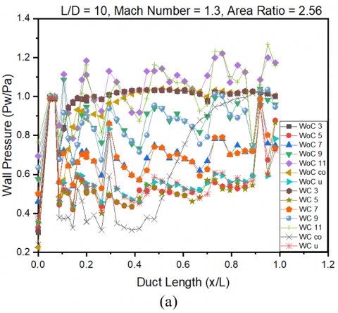
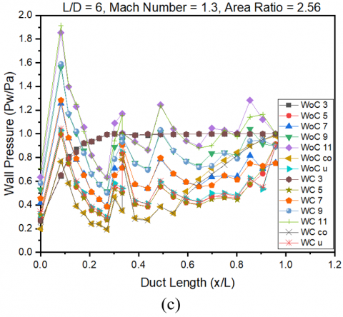
The wall pressure at a Mach number of 1.3 for different NPRs and the L/D ratios are knowledgeable in Figure 9. For Mach number 1.3, the NPR for perfect expansion is 2.59. All the NPRs are under expanded except for the results for the design NPR of the flow. It is established that at design NPR for without control case, there are oscillations of smaller magnitude; when microjet is employed, there is a decrease of wall pressure, and the flow field is getting aggravated due to the excessive interface of the Mach waves. The flow leaving from the nozzle remains under expanded for all the NPRs. The level of under expansion increases through NPR. The highest NPR level tested the flow's vibratory trend until the end of the duct, as seen in Figure 9(a). For this NPR, the wall pressure is twenty percent greater than free stream pressure. This behavior may be due to creating the waves in the duct, their interfaces with the reflected shock waves—the influence of relief available to the flow, and the effect of inertia level. A similar trend in wall pressure is seen in Figure 9(b) for L/D = 8, where all the parameters are the same; however, the duct length is 8D instead of 10D. The backpressure will impact the flow in the reduced duct length, and the same is counterfeit in the results where the wall pressure is 40% more than the free stream pressure.
Figure 9. Wall pressure plot for Mach number of 1.3
Figures 9((c) to (d)) for L/D = 6 and 5. The effect of duct length at a Mach number of 1.3 is perceived here, and the gain in wall pressure is such that its value is eighty percent more than the atmospheric pressure. The oscillations which were prevalent and L/D = 10 and 8 are not apparent in Figures 9((c) to (d)). This trend is because of atmospheric pressure that has affected the wall pressure.
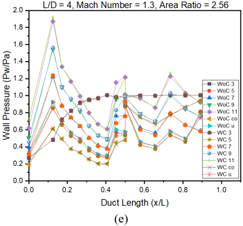
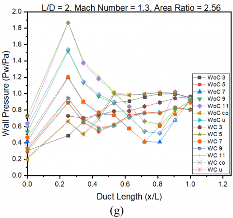
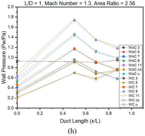
Figures 9 ((e) to (h)) show similar results as were seen for L/D = 4, 3, 2 and 1. The flow remains attached even at L/D = 1. The behavior remained unchanged due to the effect of backpressure and short reattachment duct length.
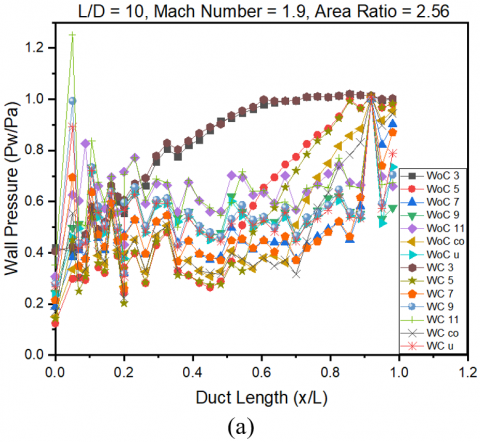
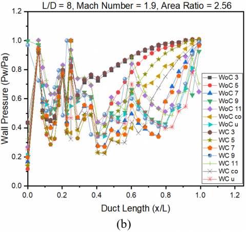
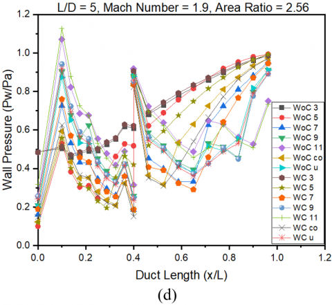
Figure 10 presents the wall pressure data at a Mach number of 1.9 at different NPRs and duct length. Figure 10(a) shows the Mach number for L/D = 10; in this case, up to NPR 5, the flow remains over expanded, resulting in the formation of an oblique shock wave at the nozzle tip. When the shear layer travels further downstream results, minimal fluctuations in the flow field, and once the flow passes the reattachment point, it results in smooth growth of the wall pressure. At x/L 0.6, the wall pressure has achieved ambient conditions. For remaining NPRs, the oscillations are observed due to the waves' presence, at NPR 11 maximum increase in wall pressure, which is 20% higher than the ambient pressure. This development is anticipated due to the waves' collaboration with the duct wall. And the intersection of the compression and expansion waves. Analogous outcomes are presented for L/D = 8 in Figure 10(b). Due to the decreased duct length, the initial increase of wall pressure, seen at L/D = 10, is not noticed. It may result due to a reduction in duct length. The backpressure must influence the flow field in the duct.
Figure 10. Wall pressure plot for Mach number of 1.9
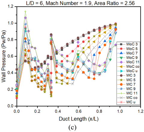
Figure 10(c) shows the consequences for L/D = 6. Due to the 40% decrease in the duct length, the oscillations have reduced considerably. The same outcomes are seen for L/D = 5 in Figure 10(d). When the duct length is lowered, it results in an additional reduction in oscillation at L/D = 4, as seen in Figure 10(e).
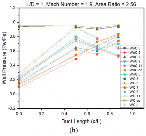
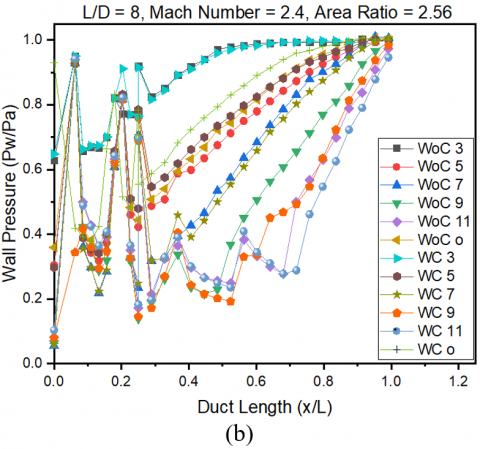
This progressive decrease is once more observed at L/D = 3 in Figure 10(f). The recovery of wall pressure is smooth, and at lower NPRs, this has been achieved within fifty percent of the duct length. This trend is attributed to the high values of the wall pressure as the nozzle flow is over-expanded. When over-expanded jets with adverse pressure gradient while exiting through nozzle passing through the oblique shock waves, attain a sudden pressure jump. The same trend continues until L/D = 2. The lowest L/D = 1 shows that the flow is attached at higher NPRs, but at lower NPRs, namely, at 3 and 5, it is not attached. Hence the wall pressure results at this length-to-diameter ratio may be discarded.
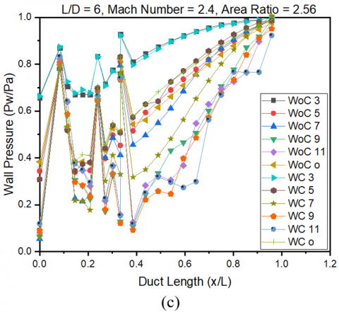
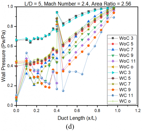
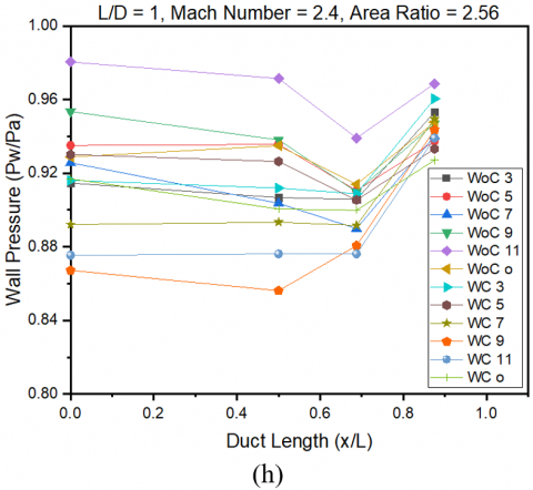
When L/D = 6 and 5, wall pressure in the tube displays in Figures 11((c) to (d)). At lower NPRs, the wall pressure starts with higher values (i.e., NPR = 3) due to a high level of over-expansion and lower duct length. This trend continues till NPR = 5. The figure shows that at NPR greater than five, the wall pressure's initial values are relative, decreasing. The drop in over expansion level may support this pattern. When we look at the other pressure values, there is a sudden jump in the wall pressure values, and the oscillations are continuing till x/L = 0.4. Additionally, along the duct's length, there is a recovery in the pipe's pressure.
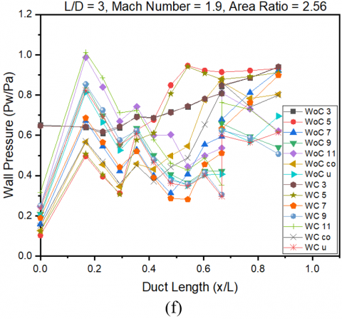
Figure 11. Wall pressure plot for Mach number of 2.4
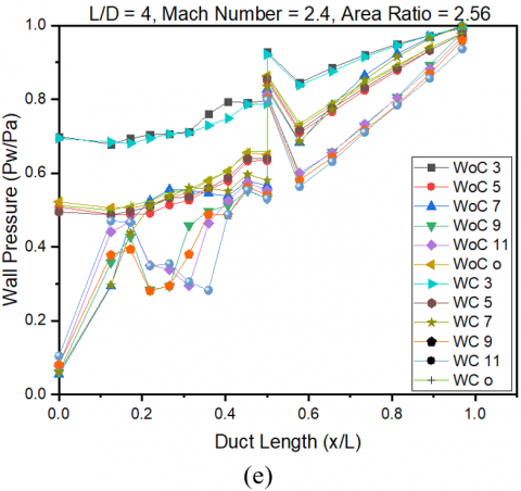
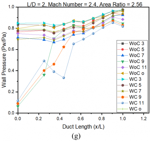
For L/D = 4 and 3, the wall pressure disparity along the duct as shown in Figures 11((e) to (f)). The results indicate that at NPR = 3, there is a further upsurge in the initial values due to the backpressure's influence. There is an overall suppression of the oscillations in the flow field of the duct. It is found that these duct lengths are enough for flow to continue to remain attached. Figures 11((g) to (h)) display the outcomes for L/D = 2 and 1. Figure 11(e) shows that at NPRs 3, 5, 7, and a fixed NPR of over-expansion, the duct is inadequate for the flow to get re-attached with the wall. However, at NPR 11, the flow does get attached to the wall of the duct. At L/D =1, the flow is no more attached to the wall; hence these results may not be considered as the duct is fully open to the ambient pressure, and the wall pressure has attained ambient conditions.
Given the above discussion, we may summarize the results as follows:
It is proven that there are oscillations of smaller magnitude at correct expansion for without control case; when microjet is employed, it results in a reduction of wall pressure, and the flow field is getting aggravated due to the excessive interference of the waves.
When the flow is coming out from the nozzle at Mach number of 1.3, it remains under expanded for all the NPRs. The level of under expansion increases through NPR.
At the highest level of NPR tested the oscillatory trend in the flow until the duct's end.
The backpressure will influence the flow in the reduced duct length, and the same is counterfeit in the results where the wall pressure is enhanced by 40% compared to atmospheric pressure.
The flow at a Mach number of 1.9 is under, over, and correctly expanded. These various levels of expansions directly impact the magnitude and quality of the static wall pressure flow field.
When we look at the results at a Mach number of 2.4, the flow remains over-expanded for the whole choice of the NPR.
The oscillations are seen in duct flow due to oblique shock as the flow passes through an adverse pressure gradient.
The flow remains attached even at L/D = 1 at a Mach number of 1.3. This requirement is increased to L/D = 2 for an increased Mach number of 1.9.
For the highest value of Mach number of 2.4, the L/D = 3 is the lowest duct length necessary for flow to remain attached to the duct wall.
|
Pw |
Wall pressure |
|
Patm/Pa |
Atmospheric pressure |
|
Pb |
Base pressure |
|
L |
Length of the duct |
|
M |
Mach number |
|
NPR |
Nozzle pressure ratio (P0/Patm) |
|
L/D |
Length to diameter ratio |
|
PCD |
Pitch circle diameter |
|
A2/A1 |
Area ratio |
|
WoC |
Without control |
|
WC |
With control |
|
co |
Correctly expanded |
|
u |
Under expansion |
[1] Khan, S.A., Rathakrishnan, E. (2002). Active control of suddenly expanded flows from overexpanded nozzles. International Journal of Turbo and Jet Engines, 19(1-2): 119-126. https://doi.org/10.1515/TJJ.2002.19.1-2.119
[2] Khan, S.A., Rathakrishnan, E. (2003). Control of suddenly expanded flows with micro-jets. International Journal of Turbo & Jet-Engines, 20(1): 63-81. https://doi.org/10.1515/TJJ.2003.20.1.63
[3] Khan, S.A., Rathakrishnan, E. (2004). Active control of suddenly expanded flows from underexpanded nozzles. International Journal of Turbo and Jet Engines, 21(4): 233-254. https://doi.org/10.1515/TJJ.2004.21.4.233
[4] Khan, S.A., Rathakrishnan, E. (2005). Active control of suddenly expanded flows from underexpanded nozzles-Part II. International Journal of Turbo & Jet-Engines, 22(3): 163-184. https://doi.org/10.1515/TJJ.2005.22.3.163
[5] Khan, S.A., Rathakrishnan, E. (2006). Active control of base pressure in supersonic regime. Journal of Aerospace Engineering, Institution of Engineers, India, 87: 1-8.
[6] Khan, S.A., Rathakrishnan, E. (2006). Control of suddenly expanded flow. Aircraft Engineering and Aerospace Technology. 78(4): 293-309. https://doi.org/10.1108/17488840610675573
[7] Khan, S.A., Rathakrishnan, E. (2006). Nozzle expansion level effect on suddenly expanded flow. International Journal of Turbo and Jet Engines, 23(4): 233. https://doi.org/10.1515/TJJ.2006.23.4.233
[8] Khan, S.A., Rathakrishnan, E. (2006). Active control of base pressure in supersonic regime. Journal of Aerospace Engineering, Institution of Engineers, India, 87: 1-8.
[9] Khan, S.A., Rathakrishnan, E. (2004). Control of suddenly expanded flow from correctly expanded nozzles. International Journal of Turbo and Jet Engines, 21(4): 255-278. https://doi.org/10.1515/TJJ.2004.21.4.255
[10] Azami, M.H., Faheem, M., Aabid, A., Mokashi, I., Khan, S.A. (2019). Experimental research of wall pressure distribution and effect of micro jet at Mach. International Journal of Recent Technology and Engineering, 8(2S3): 1000-1003. https://doi.org/10.35940/ijrte.B1187.0782S319
[11] Khan, S.A., Aabid, A., Chaudhary, Z.I. (2019). Influence of control mechanism on the flow field of duct at Mach 1.2 for Area Ratio 2.56. International Journal of Innovative Technology and Exploring Engineering, 8(6S4): 1135-1138. https://doi.org/10.35940/ijitee.F1236.0486S419
[12] Azami, M.H., Faheem, M., Aabid, A., Mokashi, I., Khan, S.A. (2019). Inspection of Supersonic Flows in a CD Nozzle using Experimental Method. International Journal of Recent Technology and Engineering, 8(2S3), 996-999. https://doi.org/10.35940/ijrte.B1186.0782S319
[13] Akhtar, M.N., Bakar, E.A., Aabid, A., Khan, S.A. (2019). Effects of micro jets on the flow field of the duct with sudden expansion. International Journal of Innovative Technology and Exploring Engineering (IJITEE), 8(9S2): 636-640. https://doi.org/10.35940/ijitee.I1129.0789S219
[14] Khan, S.A., Aabid, A., Mokashi, I., Ahmed, Z. (2019). Effect of micro jet control on the flow filed of the duct at mach 1. 5. International Journal of Recent Technology and Engineering (IJRTE), 8(2S8): 1758-1762. https://doi.org/10.35940/ijrte.B1148.0882S819
[15] Bar-Haim, B., Weihs, D. (1985). Boundary layer flow over long cylinders with suction. J. Appl. Mech., 52(1): 203. https://doi.org/10.1115/1.3168998
[16] Dowling, A.P., Mahmoudi, Y. (2015). Combustion noise. Proceedings of the Combustion Institute, 35(1): 65-100.
[17] Alrobaian, A.A., Khan, S.A., Asadullah, M., Imtiyaz, A. (2018). A new approach to low-cost open-typed subsonic compressible flow wind tunnel for academic purpose. International Journal of Mechanical and Production, 8(6): 383-394. https://doi.org/10.24247/ijmperddec201843
[18] Asadullah, M., Khan, S. A., Asrar, W., Sulaeman, E. (2018). Passive control of base pressure with static cylinder at supersonic flow. In IOP Conference Series: Materials Science and Engineering, 370(1): 1-9. https://doi.org/10.1088/1757-899X/370/1/012050
[19] Asadullah, M., Khan, S.A., Asrar, W., Sulaeman, E. (2018). Counter clockwise rotation of cylinder with variable position to control base flows. In IOP Conference Series: Materials Science and Engineering, 370(1): 012058. https://doi.org/10.1088/1757-899X/370/1/012058
[20] Asadullah, M., Khan, S.A., Asrar, W. (2017). Control of base pressure with variable location of clockwise rotating cylinder. In International Conference on Advances in Thermal Systems, Materials and Design Engineering (ATSMDE2017). pp. 1-7. http://dx.doi.org/10.2139/ssrn.3101294
[21] Asadullah, M., Khan, S.A., Asrar, W., Sulaeman, E. (2017). Active control of base pressure with counter clockwise rotating cylinder at Mach 2. In 2017 4th IEEE International Conference on Engineering Technologies and Applied Sciences (ICETAS), pp. 1-6. https://doi.org/10.1109/ICETAS.2017.8277857.
[22] Asadullah, M., Khan, S.A., Asrar, W., Sulaeman, E. (2018). Low-cost base drag reduction technique. International Journal of Mechanical Engineering and Robotics Research, 7(4): 428-432. https://doi.org/10.18178/ijmerr.7.4.428-432
[23] Khan, S.A., Mohammed, A., GM, F.A. (2018). Passive control of base drag in compressible subsonic flow using multiple cavity. Iternational Journal of Mechanical and Production Engineering Research and Development, 8: 39-44. https://doi.org/10.24247/ijmperdaug20185
[24] Khan, A., Mazlan, N.M., Ismail, M.A. (2019). Analysis of flow through a convergent nozzle at Sonic Mach Number for Area Ratio 4. Journal of Advanced Research in Fluid Mechanics and Thermal Sciences, 62(1): 66-79.
[25] Khan, A., Mazlan, N.M., Ismail, M.A. (2019). Investigation of the flowfield at sonic and supersonic mach numbers with sudden expansion. Int. J. Innov. Technol. Explor. Eng., 8(6S3): 91-95.
[26] Khan, A., Mazlan, N.M., Ismail, M.A., Akhtar, M.N. (2019). Experimental and numerical simulations at sonic and supersonic Mach numbers for area ratio 7.84. CFD Letters, 11: 50-60.
[27] Mbuyamba, J.B.M. (2013). Calculation and design of supersonic nozzles for cold gas dynamic spraying using MATLAB and ANSYS Fluent (Doctoral dissertation). http://hdl.handle.net/10539/12865
[28] Deshpande, N.D., Vidwans, S.S., Mahale, P.R., Joshi, R.S., Jagtap, R. (2014). Theoretical & CFD analysis of de laval nozzle. Internationa l Journal of Mechanical and Production Engineering, 2(4): 61-64.
[29] Patel, K.S. (2014). Flow analysis and optimization of supersonic rocket engine nozzle at various divergent angle using Computational Fluid Dynamics (CFD). IOSR Journal of Mechanical and Civil Engineering, 11(6): 01-10.
[30] Linares, M. (2015). Design Optimization of a Supersonic Nozzle Final Report. Florida International Univeristy, 2015.
[31] Belega, B.A., Nguyen, T.D. (2015). Analysis of flow in convergent-divergent rocket engine nozzle using computational fluid dynamics. In International Conference of Scientific Paper, 6.
[32] Pathan, K.A., Khan, S.A., Dabeer, P.S. (2017). CFD analysis of effect of flow and geometry parameters on thrust force created by flow from nozzle. In 2017 2nd International Conference for Convergence in Technology (I2CT): pp. 1121-1125. https://doi.org/10.1109/I2CT.2017.8226302
[33] Pathan, K.A., Khan, S.A., Dabeer, P.S. (2017). CFD analysis of effect of area ratio on suddenly expanded flows. In 2017 2nd International Conference for Convergence in Technology (I2CT), pp. 1192-1198. https://doi.org/10.1109/I2CT.2017.8226315
[34] Pathan, K.A., Khan, S.A., Dabeer, P.S. (2017). CFD analysis of effect of Mach number, area ratio and nozzle pressure ratio on velocity for suddenly expanded flows. In 2017 2nd International Conference for Convergence in Technology (I2CT), pp. 1104-1110. https://doi.org/10.1109/I2CT.2017.8226299
[35] Khan, A., Aabid, A., Khan, S.A. (2018). CFD analysis of convergentdivergent nozzle flow and base pressure control using micro-JETS. International Journal of Engineering and Technology, 7(3.29): 232-235. https://doi.org/10.14419/ijet.v7i3.29.18802
[36] Pathan, K.A., Dabeer, P.S., Khan, S.A. (2018). Optimization of area ratio and thrust in suddenly expanded flow at supersonic Mach numbers. Case Studies in Thermal Engineering, 12: 696-700. https://doi.org/10.1016/j.csite.2018.09.006
[37] Pathan, K.A., Dabeer, P.S., Khan, S.A. (2019). Investigation of base pressure variations in internal and external suddenly expanded flows using CFD analysis. CFD Letters, 11(4): 32-40.
[38] Pathan, K.A., Dabeer, P.S., Khan, S.A. (2019). Influence of expansion level on base pressure and reattachment length. CFD Lett., 11(5): 22-36
[39] Pathan, K.A., Dabeer, P.S., Khan, S.A. (2018). An investigation to control base pressure in suddenly expanded flows. International Review of Aerospace Engineering (I. RE. AS. E), 11(4): 162-169. https://doi.org/10.15866/irease.v11i4.14675
[40] Pathan, K.A., Dabeer, P.S., Khan, S. A. (2019). Effect of nozzle pressure ratio and control jets location to control base pressure in suddenly expanded flows. Journal of Applied Fluid Mechanics, 12(4): 1127-1135. https://doi.org/10.29252/jafm.12.04.29495
[41] Fharukh, A.G., Alrobaian, A.A., Aabid, A., Khan, S.A. (2018). Numerical analysis of convergent-divergent nozzle using finite element method. International Journal of Mechanical and Production Engineering Research and Development, 8(6): 373-382.
[42] Khan, S.A., Aabid, A., Baig, M.A.A. (2018). CFD analysis of CD nozzle and effect of nozzle pressure ratio on pressure and velocity for suddenly expanded flows. International Journal of Mechanical and Production Engineering Research and Development, 8: 1147-1158. https://doi.org/10.24247/ijmperdjun2018119
[43] Khan, S.A., Aabid, A., Saleel, C.A. (2019). Influence of micro jets on the flow development in the enlarged duct at supersonic Mach number. International Journal of Mechanical and Mechatronics Engineering, 19(01): 70-82.
[44] Akhtar, M.N., Bakar, E.A., Aabid, A., Khan, S.A. (2019). Numerical simulations of a CD nozzle and the influence of the duct length. International Journal of Innovative Technology and Exploring Engineering (IJITEE), 8(9S2): 622-630. https://doi.org/10.35940/ijitee.I1127.0789S219
[45] Aabid, A., Chaudhary, Z.I., Khan, S.A. (2019). Modelling and analysis of convergent divergent nozzle with sudden expansion duct using finite element method. Journal of Advanced Research in Fluid Mechanics and Thermal Sciences, 63(1): 34-51.
[46] Aabid, A., Khan, A., Mazlan, N.M., Ismail, M.A., Akhtar, M.N., Khan, S.A. (2019). Numerical simulation of suddenly expanded flow at Mach 2.2. International Journal of Engineering and Advanced Technology, 8(3): 457-462.
[47] Khan, S.A., Aabid, A., Ghasi, F.A.M., Al-Robaian, A.A., Alsagri, A.S. (2019). Analysis of area ratio in a CD nozzle with suddenly expanded duct using CFD method. CFD Letters, 11(5): 61-71.
[48] Khan, S.A., Aabid, A., Saleel, C.A. (2019). CFD simulation with analytical and theoretical validation of different flow parameters for the wedge at supersonic Mach number. International Journal of Mechanical and Mechatronics Engineering, 19(1): 170-177.
[49] Khan, S.A., Aabid, A., Mokashi, I., Al-Robaian, A.A., Alsagri, A.S. (2019). Optimization of two-dimensional wedge flow field at supersonic Mach number. CFD Letters, 11(5): 80-97.
[50] Aabid, A., Afifi, A., Ali, F.A.G.M., Akhtar, M.N., Khan, S.A. (2019). CFD analysis of splitter plate on bluff body. CFD Letters, 11(11): 25-38.
[51] Sajali, M.F.M., Ashfaq, S., Aabid, A., Khan, S.A. (2019). Simulation of effect of various distances between front and rear body on drag of a non-circular cylinder. Journal of Advanced Research in Fluid Mechanics and Thermal Sciences, 62(1): 53-65.
[52] Sajali, M.F.M., Aabid, A., Khan, S.A., Mehaboobali, F. A.G., Sulaeman, E. (2019). Numerical investigation of flow field of a non-circular cylinder. CFD Letters, 11(5): 37-49.
[53] Kharulaman, L., Aabid, A., Mehaboobali, F.A.G., Khan, S.A. (2019). Research onFlows for NACA 2412 Airfoil using computational fluid dynamics method. Int. J. Eng. Adv. Technol., 9(1): 5450-5456. https://doi.org/10.35940/ijeat.A3085.109119
[54] Quadros, J.D., Khan, S.A., Antony, A.J. (2018). Study of base pressure behavior in a suddenly expanded duct at supersonic Mach number regimes using statistical analysis. Journal of Applied Mathematics and Computational Mechanics, 17(4): 59-72. https://doi.org/10.17512/jamcm.2018.4.07
[55] Quadros, J.D., Khan, S.A., Antony, A.J. (2017). Investigation of effect of process parameters on suddenly expanded flows through an axi-symmetric nozzle for different Mach Numbers using design of experiments. In IOP Conference Series: Materials Science and Engineering, 184(1): 012005. https://doi.org/10.1088/1757-899X/184/1/012005
[56] Afzal, A., Aabid, A., Khan, A., Khan, S.A., Rajak, U., Verma, T.N., Kumar, R. (2020). Response surface analysis, clustering, and random forest regression of pressure in suddenly expanded high-speed aerodynamic flows. Aerospace Science and Technology, 107: 106318. https://doi.org/10.1016/j.ast.2020.106318
[57] Al-Khalifah, T., Aabid, A., Khan, S.A. (2020). Regression analysis of flow parameters at high mach numbers. Solid State Technology, 63(6): 5473-5488.
[58] Aabid, A., Khan, S.A. (2021). Investigation of high-speed flow control from CD nozzle using design of experiments and CFD methods. Arabian Journal for Science and Engineering, 46(3): 2201-2230. https://doi.org/10.1007/s13369-020-05042-z