Ruslan S. Abdulrahman* | Farah A. Ibrahim | Safaa H. Faisel
© 2020 IIETA. This article is published by IIETA and is licensed under the CC BY 4.0 license (http://creativecommons.org/licenses/by/4.0/).
OPEN ACCESS
The heat exchanger (HX) plays a key role for several industries, to reduce the energy consumption by rising heat transfer rate through heat exchanger. In this study, numerical simulation of shell and double tube heat exchanger without and with baffles is analyzed to evaluate the heat transfer and exergy analysis. A numerical simulation of 3D model with turbulent flow at the range (4000-12000) is performed with commercial computational fluid dynamics (CFD) software ANSYS (Fluent). The circular vents baffles model is used at the side of the shell. The simulation results show that the circular vents on the baffles of the heat exchanger have a significant impact on thermal- hydraulic performance and exergy analysis. Also, the results show that the heat exchanger effectiveness with baffles increases by 17% at high Reynolds number comparing with heat exchanger without baffles. Besides, the highest value of exergy loss reached to 42W with baffles presence. Finally, it is concluded that the heat exchanger with baffles gives better hydraulic and thermal performance than that of heat exchanger without baffles.
double tube heat exchanger, baffles, turbulent flow, exergy analysis, CFD
Energy conservation is one of the most important subjects of the century and will certainly be one of the most important challenges in the near future. Advances in cooling or heating processes for industrial appliances lead to energy saving, improved heat transfer and increases the operating life of the device. For the above purpose, different types of heat exchangers (HXs) are utilized in several industrial areas like: petrochemical industry, chemical and nuclear reactors, condenser and boiler in power plants, air-conditioning and refrigeration process [1].
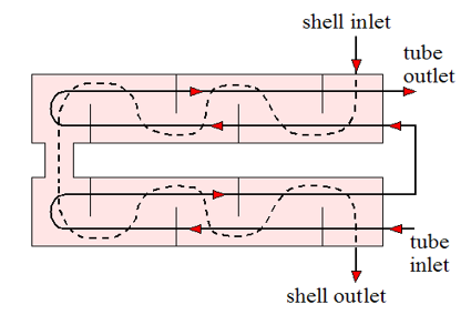
The "heat exchanger" could be described as a device for transmitting energy between two fluids at the maximum rate and the lowest operating cost [1]. Basis on the design, most HXs include the tubular type which is widely utilized in industry [2]. In this HX, one fluid flows through tubes and another fluid passes in the shell within the bundle of tubes [3]. A tubular HX may be classified in following kinds: shell and tube heat exchanger (STHX), double tube heat exchanger and coiled tube heat exchanger [4]. The double tube HX has great heat transfer efficiency especially with straight baffles design. Baffles are generally placed on the fluid side of the shell to improve the convection coefficient by inducing turbulence. Also, these physically support the tubes. A two shell passes and double tube HX with baffles is seen in Figure 1 [5].
Many research analyses have been conducted in the circular double tube HX through the recent years. Pamuk [6] introduced a numerical simulation to study the effect of baffles for concentric tube HX. He considered two different models, one is simple model of HX with baffles and another includes a greater model three baffles. Numerical results showed that the ANSYS Fluent yields accurate outputs as far as the heat transfer and hydrodynamics in the flow of fluid during the concentric tube HX. The distribution of velocity, pressure and temperature in the oil flow inside HX were also presented. Etghani and Baboli [7] preformed a numerical analysis and optimization for thermal conditions and loss of exergy of shell with helical tube HX. A three-dimensional model with laminar flow was proposed in their study. The effects of four parameters like: tube diameter, pitch coil, cold and hot flow rate were examined. In their conclusions, they observed that the cold flow rate and tube diameter had the most important parameters of exergy loss and heat transfer. Fahad et al. [8] introduced a numerically simulation to determine the thermal properties of STHX with baffles under laminar flow. They studied the effect the angle inclination of tube baffles as (–45°, 0° and 45°) on the performance of heat exchanger. From their analysis, they observed that the angle of baffles at 45° increases in the heat transfer rate at high Reynolds number. Zhou et al. [9] proposed a numerical study to investigate the heat transfer and pressure drop characteristics of forced convection of the STHX with trefoil- hole baffles. Their results indicated that, the flow of fluid after the first holes baffle was fully developed. They also found that the coefficient of heat transfer and pressure drop varied periodically the length of the axial direction. Teja and Narasimha Rao [10] developed a 3D numerical model for HX with a hexagonal vents baffles. They studied the heat transfer improvement by CFD simulation under turbulent flow. The results appeared that, the coefficient of heat transfer was higher for hexagonal vents baffles regardless of the hexagonal vent locations on different tubes. Santhisree et al. [11] presented the thermal and hydraulic performance for heat exchanger containing 4 baffles and 22 tubes. They used CFD software to simulate the thermal analysis. Also, the velocity, temperature and pressure counters were introduced. Sadikin et al. [12] studied the effect of baffles number and the spacing of the baffles on pressure drop and flow for STHX. Their numerical analysis was done with CFD simulation for 3D model. The results showed that the variable baffles number and the spacing of the baffles for HX strongly affect the pressure drop and flow pattern. dos Santos Filho et al. [13] described a mathematical model for STHX. The baffles influence of fluid behaviors was analyzed. They observed through simulation that the effectiveness of thermal exchange increased with presence of baffles. Also, they presented the counters of fluid behaviors. Yang and Liu [14] introduced numerical and experimental report to reveal the properties of flow and heat transfer of STHX. They used in their numerical simulation of HX with plate and rod baffles. The results measured of their experiments and simulation analysis showed that, the Nusselt number for the HX with plate baffles was around 128-139% of that for the HX with rod baffles. Kirinčić et al. [15] presented a numerical and experimental study of a small size STHX with segmental baffles. They considered a 3D model with laminar flow and steady state. Hence, they found a very well agreement between experimental investigation and the numerical modelling of the heat transfer problem.
The purpose of this work is to simulate the thermal behavior and exergy analysis of three-dimensional model in shell and double tube HX with and without baffles. This model consists of one pass of the shell with circular vents baffles and four passes of tube for the purpose of increasing the surface area for heat transfer. In numerical calculation, the steady state, incompressible and (k-$\varepsilon$) model are considered to solve the governing equations.
Figure 1. Two shell passes and double tube heat exchanger with baffles [5]
2.1 Geometrical model descriptions
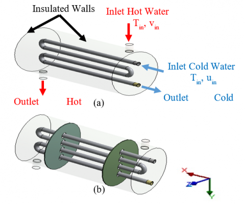
The geometry (3D) of the numerical simulation is presented in Figure 2 which represents the shell and double tube HX without and with baffles respectively. It consists of one pass at the shell and four passes of tube. The dimensions details of the heat exchanger are listed in Table 1. Generally, cold water flows through the double tube and is heated by a cross-parallel flow of hot water passing in the shell. Two baffles with circular vents are used at a fixed angle around the shell diameter to promote heat transfer. To simplify computation domain, several basic assumptions are made:
• Heat transfer and fluid flow were in three-dimensional and steady state.
• The fluid flow for tube and shell sides was turbulent and incompressible.
• The thermo and physical properties of fluids were independent of temperature.
• Gravity effect was negligible.
• Baffles and tube wall separating between hot and cold fluids were considered Aluminum walls.
Table 1. Dimensions of heat exchanger
|
Description |
Size |
|
Shell diameter |
24 mm |
|
Inlet and outlet diameter of shell |
3 mm |
|
Tube internal dimeter |
2 mm |
|
Tube external dimeter |
2.2 mm |
|
Tube thickness, $\delta_{t}$ |
0.1 mm |
|
Total tube length |
200 mm |
|
Heat exchanger length, L |
52 mm |
|
Number of baffles |
2 |
|
Baffle spacing |
26 mm |
|
Baffles thickness |
0.3 mm |
|
Diameter of vent circle |
3 mm |
|
Baffle inclination |
0° |
Figure 2. Three-dimensional diagram for heat exchanger: (a) without baffles, (b) with baffles
2.2 Governing equations
Depending on the above assumptions, the governing equations for turbulent flow (k-ε) model and steady state heat transfer problem can be presented below in cartesian coordinate system [16]:
(i). Continuity equation:
$\frac{\partial u_{j}}{\partial x_{j}}=0$ (1)
(ii). Momentum equation:
$\frac{\partial\left(u_{i} u_{j}\right)}{\partial x_{j}}=-\frac{1}{\rho} \cdot \frac{\partial P}{\partial x_{i}}+\frac{1}{\rho} \cdot \frac{\partial}{\partial x_{j}}\left[\mu_{e f f}\left(\frac{\partial u_{i}}{\partial x_{j}}-\frac{\partial u_{j}}{\partial x_{i}}\right)\right]$ (2)
(iii). Energy equation:
$\frac{\partial\left(C_{P} u_{j} T\right)}{\partial x_{j}}=\frac{1}{\rho} \cdot \frac{\partial}{\partial x_{j}}\left(\lambda_{e f f} \frac{\partial T}{\partial x_{j}}\right)$ (3)
where, P, T and u refer to fluid pressure, temperature and velocity respectively; Cp and ρ stand for specific heat constant pressure and density of fluid respectively; μeff is the effective dynamic viscosity and can be calculated by the sum the dynamic viscosity of laminar and turbulent:
$\mu_{\text {eff }}=\mu_{l}+\mu_{t}$ (4)
The effective thermal conductivity, λeff equal to:
$\lambda_{e f f}=\lambda_{l}+\lambda_{t} C_{P} / P r_{t}$ (5)
where, Prt refer to turbulent Prandtl number, λl and λt are the laminar and turbulent conductivity.
The model of standard k-ε turbulence is considered with standard wall function for the present computation. The transport equations of kinetic energy of the turbulence and its dissipation rate are as follow:
The turbulence kinetic energy k:
$\frac{\partial\left(k u_{j}\right)}{\partial x_{j}}=\frac{1}{\rho} \cdot \frac{\partial}{\partial x_{j}}\left[\left(\mu_{l}+\frac{\mu_{t}}{\sigma_{k}}\right) \frac{\partial k}{\partial x_{j}}\right]+\frac{G_{k}}{\rho} \varepsilon$ (6)
The rate of dissipation of the turbulence kinetic energy $\varepsilon$:
$\frac{\partial\left(\varepsilon u_{j}\right)}{\partial x_{j}}=\frac{1}{\rho} \cdot \frac{\partial}{\partial x_{j}}\left[\left(\mu_{l}+\frac{\mu_{t}}{\sigma_{\varepsilon}}\right) \frac{\partial \varepsilon}{\partial x_{j}}\right]+\frac{C_{1 \varepsilon} \varepsilon}{\rho k} G_{k}-C_{2 \varepsilon} \frac{\varepsilon^{2}}{k}$ (7)
where,
$\mu_{t}=\rho C_{\mu} \frac{k^{2}}{\varepsilon} ; G_{k}=2 \mu_{t} E_{i j} \cdot E_{i j} ; E_{i j}=\frac{1}{2}\left(\frac{\partial u_{i}}{\partial x_{i}}+\frac{\partial u_{i}}{\partial x_{j}}\right)$ (8)
The constant for the current turbulent model is set as below [16]:
$C_{\mu}=0.09 ; C_{1 \varepsilon}=1.44 ; C_{2 \varepsilon}=1.92 ; \sigma_{k}=1.0 ; \sigma_{\varepsilon}=1.3$
2.3 Boundary conditions
The boundary conditions for modelling are shown in Figure 2. Generally, there are two inlets and two outlets in shell and double tube HX. The inlets are defined as velocity with temperature and outlets are defined as pressure outlets. Different Reynolds numbers ranging from 4000 to 12000 are used for cold and hot water at inlet region. Inlet temperature of tube and shell are adopted at 300 K and 360K respectively. The shell walls are considered as insulated. The baffles and tube wall separating between hot and cold fluids are considered as domain interface wall. The boundary conditions for the numerical calculation are set below:
2.3.1 Inlet
$u=u_{i n}, v=w=0, T=T_{i n}$ for tube side
$v=v_{i n}, u=w=0, T=T_{i n}$ for shell side
2.3.2 Outlet
$\left.\begin{array}{l}\frac{\partial u}{\partial x}=\frac{\partial v}{\partial x}=\frac{\partial w}{\partial x}=0, \frac{\partial T}{\partial x} \\ \frac{\partial k}{\partial x}=\frac{\partial \varepsilon}{\partial x} \text { and } P_{\text {out }}=0\end{array}\right\}$ for tube side
$\left.\begin{array}{l}\frac{\partial u}{\partial y}=\frac{\partial v}{\partial y}=\frac{\partial w}{\partial y}=0, \frac{\partial T}{\partial y} \\ \frac{\partial k}{\partial y}=\frac{\partial \varepsilon}{\partial y} \text { and } P_{\text {out }}=0\end{array}\right\}$ for shell side
2.3.3 Walls
(i). External shell walls were insulated boundary:
$u=v=w=0$ and $\frac{\partial T}{\partial x}=\frac{\partial T}{\partial y}=\frac{\partial T}{\partial z}=0$
(ii). Internal walls
• Tube wall, solid-fluid interfaces (no-slip, conjugate heat transfer)
$u=v=w=0,-\lambda_{f} \frac{\partial T_{f}}{\partial y}=-\lambda_{s} \frac{\partial T_{s}}{\partial y}$.
• Baffles, solid-fluid interfaces (no-slip, conjugate heat transfer)
$u=v=w=0,-\lambda_{f} \frac{\partial T_{f}}{\partial x}=-\lambda_{s} \frac{\partial T_{s}}{\partial x}$.
where, f=fluid (water) and s=solid (Aluminum walls).
2.4 Mesh and computation method
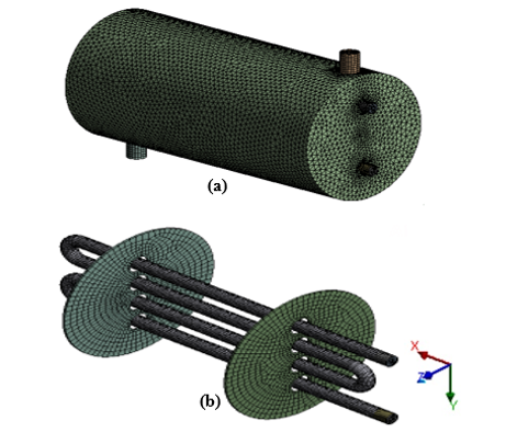
A 3D geometry of a heat exchanger and grids was drawn by ANSYS workbench. A fine tetrahedral and hexahedral mesh was used in the modelling as shown in Figure 3. The meshes contain 936375 elements for heat exchanger without baffles and 964776 elements with baffles. Governing equations were solved by using FLUENT code based on finite volume technique and SIMPLE algorithm. The first order upwind scheme was assumed for the energy, momentum, kinetic energy of turbulence and dissipation rate, whereas the pressure term was treated using the second order upwind scheme. Absolute criterion of convergence was set to 10-4 for all variables. The values of relaxation factors for the energy equation, momentum equations, kinetic energy of turbulence, pressure correction equation and turbulence dissipation rate were set to 1, 0.5, 0.8, 0.3 and 0.8 respectively.
Figure 3. Meshing of the physical model: (a) heat exchanger without baffles, (b) partial meshes of baffles and tube
2.5 Exergy methodology
Exergy of a system was described as the maximum useful work that can be drawn from a system because it comes in balance with its environment. The shaft work of the HX is insignificant, therefore, the exergy gets from the comparable flow fluids and described in the exergy equilibrium.
Exergy loss for steady control volume may be determined in relationship below [7]:
$E x_\dot{\text {loss }}=T_{o}\left[\dot{m}_{c} C_{p c} \ln \left(T_{c, \text { out }} / T_{c, \text { in }}\right)+\dot{m}_{h} C_{p h} \ln \left(T_{h, \text { out }} / T_{h, \text { in }}\right)\right]$ (9)
Exergy efficiency is measured as a change in the availability of the cold stream divided by change in the availability of the hot stream. That is [17]:
$\eta_{\Pi}=\frac{\dot{m}_{c}\left(\psi_{c, o}-\psi_{c, i}\right)}{\dot{m}_{h}\left(\psi_{h, i}-\psi_{h, o}\right)}$ (10)
where,
$\dot{m}_{c}\left(\psi_{c, o}-\psi_{c, i}\right)=\dot{m}_{c}\left[\left(h_{c, o}-h_{c, i}\right)-T_{o}\left(s_{c, o}-s_{c, i}\right)\right]$ (11)
$\dot{m}_{h}\left(\psi_{h, i}-\psi_{h, o}\right)=\dot{m}_{h}\left[\left(h_{h, i}-h_{h, o}\right)-T_{o}\left(s_{h, i}-s_{h, o}\right)\right]$ (12)
In which, $\dot{m}_{c} \text { and } \dot{m}_{h}$ refer to mass flow rate of cold and hot respectively; $\left(\psi_{c, o}-\psi_{c, i}\right)$ is the availability change between the outlet cold and inlet cold; $\left(\psi_{h, i}-\psi_{h, o}\right)$ is the availability change between inlet hot and outlet hot; h and s stand for enthalpy and entopy respectively and To is environment temperature.
3.1 Grid independent study
To obtain accurate results with good grid, three different grid sizes are tested and shown in Table 2. The illustrates the results of grid independent for the outlet temperature of the shell side with Reynolds number of tube side for heat exchanger without and with baffles as seen in Figure 4. It can be noted from figure that, there is no significant change on the results when the grid sizes increase and only the operation time increases. Therefore, a grid containing 936375 cells and 964776 cells are employed in this study for heat exchanger without and with baffles respectively.
3.2 Characterization of thermal and hydraulic behaviors
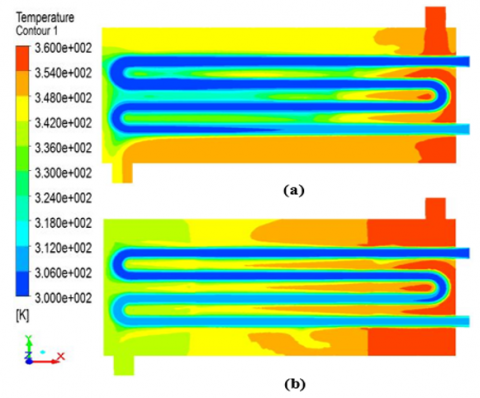
Figure 5 shows 2D temperature distribution contours at a longitudinal central plane of a complete heat exchanger unit (shell and double tube) at (x-y) plane. It is noticed that, the temperature of hot water on the side of the shell decreased along the heat exchanger, while the cold water temperature from the side of the pipe gradually increases for both heat exchangers. In Figure 5 (b), it can be noted that the temperature difference between the inlets and outlets of the heat exchanger is high compared to Figure 5 (a). This is due the presence the baffles that generate the high turbulence swirling leading to increase the heat transfer between two liquids. This means that the hot water stays longer in the heat exchanger, increasing the time available to heat transfer to the cold water. For these cases, the tube outlet temperature was increased by about 308 K for without baffles, 312 K for with baffles, while shell outlet temperature was decreased by about 347 K for without baffles, 340 K for with baffles.
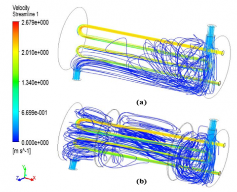
The 3D streamlines plots of hot water flow along the heat exchanger are shown in Figure 6 at Reshell=4000. Figure 6 (a) appears that the most of hot water flows uniformly and longitudinally towards the shell outlet. In Figure 6 (b), the acceleration and expansion of the hot fluid flow across baffles can be observed along the HX. The results explain that the presence of baffles caused the flow direction varies, which produces multi-directional stream, then lead to enhancement in the turbulence. This is due to a decrease in the area of flow of the vents on the baffles and thus leads to a sharp increase in velocity. So, the highest velocity of 0.06 m/s is observed near the circular vents compared to surface far away from the vents. Since the baffle block, the hot water flow in front of the baffles from the center to the shell edge and then the hot water flows across the baffles back to the center form the edge, leading to the production of a secondary flow that promotes the heat transfer of the shell side.
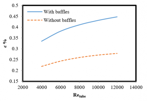
Figure 7 shows the effect of both the baffles and tube Reynolds number on heat exchanger effectiveness which is defined as:
$\epsilon=\frac{Q_{a c t .}}{Q_{\max .}}=\frac{\dot{m} C p\left(T_{h i}-T_{h 0}\right)}{(\dot{m} C p) \min \left(T_{h i}-T_{c i}\right)}$ (13)
Table 2. Grid independent study
|
Grid |
Grid size of heat exchanger without baffles |
Grid size of heat exchanger with baffles |
|
Grid I |
936375 |
964776 |
|
Grid II |
940772 |
969171 |
|
Grid III |
943939 |
975950 |
Figure 4. Grid independence test results for numerical solution of heat exchanger at Reshell=4000: (a) without baffles, (b) with baffles
It can be noted that, the HX with baffles has the higher effectiveness values than that without baffles, due the presence of circular vents on the baffles which causing the turbulence and random movement of the flow field resulting in improved heat transfer between fluids. So, the values of heat exchanger effectiveness with baffles are about 34 - 45% of the values without baffles. At the same time it is observed that, the effectiveness increased as cold water Reynolds number increased due to the high velocity. These results are an agreement with [8].
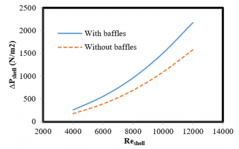
Figure 8 displays the variation of pressure drop of shell side versus shell Reynolds number. The results show that the HX with baffles has a high pressure drop. This indicates that, the baffles act as a guide and obstacles to the flow, which leads to increase the pressure drop. Generally, the direction of fluid flow in a HX without baffles is from the entrance to the exit, so the only effects that cause pressure drop will come from crossing the pipe and friction along the wall of the shell. Therefore, the adding of baffles will disable the flow of fluids to go in the general direction and thus increase the pressure drop. Moreover, there is an increase in pressure drop gradually with increase in shell Reynolds number for both heat exchangers, due to increase of velocity.
Figure 5. Contours of temperature distribution at a longitudinal central plane for heat exchanger at Re=4000: (a) without baffles, (b) with baffles
Figure 6. Streamlines plots of hot water flow along heat exchanger at Re=4000: (a) without baffles, (b) with baffles
Figure 7. Effect of both the baffles and tube Reynolds number on heat exchanger effectiveness
Figure 8. Variation of pressure drop of shell side vs. shell Reynolds number
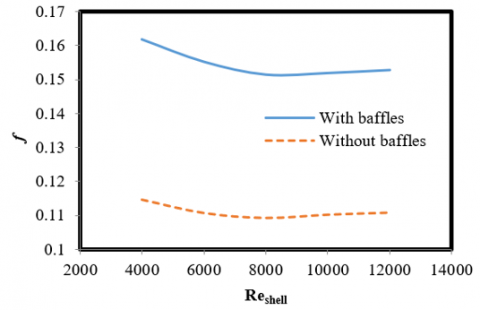
Figure 9 reveals the variation of shell friction coefficient value on various Reynolds number of the shell which is found by:
Figure 9. Variation of shell friction coefficient value on various Reynolds number of the shell
$f=\frac{2 D_{h} \Delta P}{\rho L u^{2}}$ (14)
As shown in this figure, the friction coefficient of HX without baffles is less than that with baffles. The results also showed that the coefficient of friction decreased when increasing the shell Reynolds number for both heat exchangers due to increase the velocity. This was in agreement with fluid science, the friction coefficient was directly inversely to velocity.
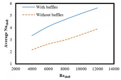
Figure 10 shows the effect of both the baffles and tube Reynolds number on average Nusselt number of tube side. The average Nu value is calculated by integrating of local Nu along HX using a trapezoidal rule:
$\overline{\mathrm{Nu}}=\frac{1}{L} \int_{0}^{L} N u d x$ (15)
As seen from this figure that, the influence of baffles on the average Nusselt number for heat exchanger is relatively large. The reason for this indicates to that the Nusselt number is enhanced by strong mixing of the fluid produced by the baffles. The maximum Nusselt number is approximately of 5.7 in this case. Moreover, Nusselt number increases with increased Reynolds number of cold water due to increase in heat transfer coefficient of the HX. These results are an agreement to Yang and Liu [14].
Figure 10. The effect of both the baffles and tube Reynolds number on average Nu of tube side
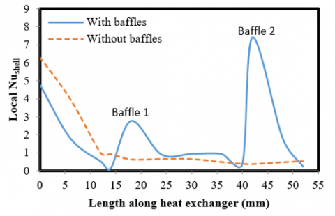
The distribution of local Nusselt number along flow direction of shell side for various Reynolds numbers is shown in Figure 11, which is expressed as:
Figure 11. Local Nusselt number distribution along flow direction at various shell Reynolds number
$N u_{\text {Local }}=\frac{\bar{h}_{(C F D)} D_{h}}{K_{f}}$ (16)
As can be seen from this figure, higher Nusselt number values for HX with baffles are found and a highest value of 7.5 is observed near the baffle located at the heat exchanger exit, while the Nusselt number decreased to constant value towards the exit for HX without baffles.
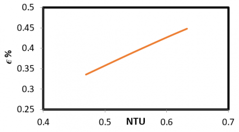
Figure 12 illustrates the variation of NTU versus effectiveness for HX with baffles. The values of NTU are computed by:
$\mathrm{NTU}=\frac{\mathrm{U} A_{s}}{(m \cdot c p)_{\min }}$ (17)
where:
$\frac{1}{U}=\frac{1}{h_{i}}+\frac{\delta_{t}}{k_{t}}+\frac{1}{h_{0}}$ (18)
As can be shown, by increasing in the effectiveness, the NTU is also increased. These results are an agreement with [17].
Figure 12. Variation the effectiveness vs. NTU for heat exchanger with baffles
3.3 Exergy analysis
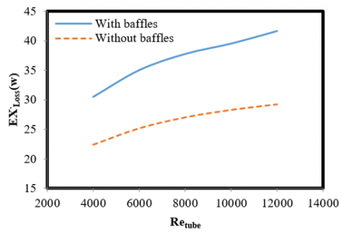
Figure 13 presents the difference of exergy loss between heat exchanger with baffles and without baffles. The value of exergy loss is found by Eq. (9).
Figure 13. Variation of exergy loss vs. different tube Reynolds number
It is show that the exergy loss increases as increasing Reynolds number of cold water for both heat exchangers. The exergy loss of the HX with baffles is larger than that without baffles. The highest value of exergy loss is about of 42 W for this case. This reason is due to presence of circular holes on the baffles are gives high swirling, which increase of heat transfer rate. Moreover, the heat transfer rate increases with increased temperature difference between the inlets and outlets fluids. This parameter plays an important role for exergy loss. These results are an agreement to Etghani and Baboli [7].
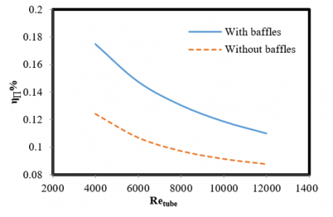
Figure 14. Exergy efficiency vs. tube Reynolds numbers
Figure 14 shows the exergy efficiency versus tube Reynolds numbers. The value of exergy efficiency is computed by Eq. (10). It is appeared that the efficiency of each HX is decreased with increasing tube Reynolds numbers due to increased temperature difference between inlet and outlet fluids leading to reduced entropy. This result is an agreement well with Bashtani and Esfahani [17].
The heat exchanger contributes significantly to many processes of energy conversions and we were interested in the current work to examine the thermal behavior and exergy analysis in the shell and double tube HX. A three-dimensional model of the shell and double tube HX without and with circular vents baffles was simulated using ANSYS (Fluent) software. The main conclusions could be summarized as follows:
(1) The HX with baffles has a greater influence in increasing the effectiveness about 17% at high Reynolds number than without baffles.
(2) The results indicated that, the highest Nusselt number and pressure drop versus Reynolds number were achieved by HX with baffles.
(3) The HX with baffles has highest values of loss and exergy efficiency compared to without baffles.
Finally, it was concluded that the HX with baffles gives better thermal and hydraulic performance than that without baffles because this design contributes to an increase the surface area and a longer stay of fluid, which leads to enhanced heat transfer. In addition, the ANSYS Fluent played an active role to predict the thermal and hydraulic behaviors of double tube HX.
|
As |
surface area, m |
|
Cp |
heat capacity, J. kg-1. K-1 |
|
Dh |
hydraulic diameter, mm |
|
f |
friction coefficient |
|
h |
enthalpy, J. K-1 |
|
$\bar{h}$ |
heat transfer coefficient, W. m-2. K-1 |
|
kf |
fluid thermal conductivity, W. m-1. K-1 |
|
kt |
tube thermal conductivity, W. m-1. K-1 |
|
L |
length of heat exchanger, mm |
|
$\dot{m}$ |
mass flow rate, kg.s-1 |
|
Nu |
Nusselt number = (h Dh / k) |
|
$\overline{N u}$ |
average Nusselt number |
|
NTU |
numbers of transfer units |
|
Pout |
pressure at outlet, Pa |
|
Pr |
Prandtl number |
|
Q̇ |
heat transfer rate, W |
|
Re |
Reynolds number = $\left(\rho \mathrm{u}_{\mathrm{in}} \mathrm{D}_{\mathrm{h}} / \mu\right)$ |
|
s |
entropy, J..kg-1. K-1 |
|
Tin |
inlet temperature, K |
|
To |
environment temperature, K |
|
U |
overall heat transfer coefficient, W. m-2. K-1 |
|
uin |
inlet velocity in x-direction, m. s-1 |
|
vin |
inlet velocity in y-direction, m. s-1 |
|
Abbreviations |
|
|
CFD |
computational fluid dynamics |
|
$\dot{E x}$ |
exergy loss, W |
|
HX |
heat exchanger |
|
STHX |
shell and tube heat exchanger |
|
Greek symbols |
|
|
$\epsilon$ |
heat exchanger effectiveness |
|
ε |
turbulent dissipation rate |
|
η∏ |
exergy efficiency |
|
$\left(\psi_{c, o}-\psi_{c, i}\right)$ |
availability change of the cold stream, J.kg-1 |
|
$\left(\psi_{h, i}-\psi_{h, o}\right)$ |
availability change of the hot stream, J.kg-1 |
|
μ |
dynamic viscosity, Pa.s |
|
$\lambda$ |
thermal conductivity, W. m-2. K-1 |
|
δt |
tube thickness, mm |
|
ρ |
density, kg. m-3 |
|
∆P |
pressure drop, N.m-2 |
|
Subscripts |
|
|
a |
actual |
|
c |
cold |
|
eff |
effective |
|
f |
fluid |
|
h |
hot |
|
i |
inlet |
|
l |
laminar |
|
max |
maximum |
|
min |
minimum |
|
o |
outlet |
|
s |
solid |
|
t |
turbulent |
[1] Mule, B.A., Hatkar, D.N., Bembde, M.S. (2017). Analysis of double pipe heat exchanger with helical fins. International Research Journal of Engineering and Technology, 4(8): 2395-0072.
[2] Irshad, M., Kaushar, M., Rajmohan, G. (2017). Design and CFD analysis of shell and tube heat exchanger. International Journal of Engineering Science and Computing, 7(4): 6453-6457.
[3] Afsar, N., Inam, M.I. (2018). CFD analysis of shell and tube heat exchanger with different baffle orientation and baffle cut. AIP Conference Proceedings, 1980(1): 050006. https://doi.org/10.1063/1.5044342
[4] Shriwas, D., Saini, J., Sahu, P.K. (2018). Numerical simulation and CFD analysis of double tube heat exchanger with different tube geometries on same cross section area. International Journal for Scientific Research, 6(5): 2321-0613.
[5] Singh, D.S., Pal, N.D. (2016). Designing and performance evaluation of a shell and tube heat exchanger using Ansys. International Journal of Scientific Engineering and Applied Science, 2(3): 2395-3470.
[6] Pamuk, M.T. (2019). Numerical investigation of the effects of the baffles added in a concentric pipe heat exchanger. International Journal of Heat and Technology, 37(2): 583-588. https://doi.org/10.18280/ijht.370228
[7] Etghani, M.M., Baboli, S.A.H. (2017). Numerical investigation and optimization of heat transfer and exergy loss in shell and helical tube heat exchange. Applied Thermal Engineering, 121: 294-301. http://dx.doi.org/10.1016/j.applthermaleng.2017.04.074
[8] Fahad, S., Alshara, A.K., Saeed, M. (2017). Numerical investigation of heat transfer and flow characteristics in shell and U-tube heat exchanger with baffles. Journal of University of Duhok, 20: 404-415. https://doi.org/10.26682/sjuod.2017.20.1.37
[9] Zhou, G., Xiao, J., Zhu, L., Wang, J., Tu, S. (2015). A numerical study on the shell-side turbulent heat transfer enhancement of shell and tube heat exchanger with trefoil hole baffles. Energy Procedia, 75: 3174-3179. https://doi.org/10.1016/j.egypro.2015.07.656
[10] Teja, G.V., Narasimha Rao, K.V. (2017). Numerical investigation on heat transfer and fluid flow of shell-side for shell and tube heat exchanger with hexagonal vent baffle by using CFD. International Journal of Mechanical Engineering and Technology, 8(5): 995-1009. http://www.iaeme.com/IJMET/index.asp.
[11] Santhisree, N., Prashanthkumar, M., Priyanka, G. (2017). Thermal analysis of shell and tube heat exchanger. International Journal of Mechanical Engineering and Technology, 8(5): 596-606.
[12] Sadikin, A., Khian, N.Y., Hwey, Y.P., Al-Mahdi, H.Y., Taib, I., Sadikin, A.N., Salleh, S.M., Ayop, S.S. (2018). Effect of number of baffles on flow and pressure drop in a shell side of a shell and tube heat exchangers. Journal of Advanced Research in Fluid Mechanics and Thermal Sciences, 48(2): 156-164.
[13] dos Santos Filho, S.J., de Souza, J.S., de Lima, A.G.B. (2017). Numerical simulation of the shell-and-tube heat exchanger: Influence of the lower flows and the baffles on a fluid Dynamics. Advances in Chemical Engineering and Science, 7(4): 78727. https://doi.org/10.4236/aces.2017.74026
[14] Yang, J., Liu, W. (2015). Numerical investigation on a novel shell-and-tube heat exchanger with plate baffles and experimental validation. Energy Conversion and Management, 101: 689-696. http://dx.doi.org/10.1016/j.enconman.2015.05.066
[15] Kirinčić, M., Trp, A., Lenić, K. (2017). Numerical investigation and experimental validation of heat transfer in a small size shell and tube heat exchanger. Engineering Review, 37(2): 122-133.
[16] You, Y., Chen, Y., Xie, M., Luo, X., Jiao, L., Huan, S. (2015). Numerical simulation and performance improvement for a small size shell-and tube heat exchanger with trefoil-hole baffles. Applied Thermal Engineering, 89: 220-228. https://doi.org/10.1016/j.applthermaleng.2015.06.012
[17] Bashtani, I., Esfahani, J.A. (2019). ε - NTU analysis of turbulent flow in a corrugated double pipe heat exchanger: A numerical investigation. Applied Thermal Engineering, 159: 113886. https://doi.org/10.1016/j.applthermaleng.2019.113886