Shankar Badiger* | Vadiraj V. Katti | Anil R. Tumkur
© 2020 IIETA. This article is published by IIETA and is licensed under the CC BY 4.0 license (http://creativecommons.org/licenses/by/4.0/).
OPEN ACCESS
Flame jet has a wide range of applications in the industries and also in domestics field. The efforts have been put to enhance the heat transfer and to reduce the emissions from the premixed and inverse diffusion flame burners. Especially, the IDF burner suffers from lack of proper air and fuel mixing, the swirl generated motion from twisted tape would improve the combustion efficiency. Therefore, an aim of experiment is to study the heat transfer characteristics of an inverse diffusion flame (IDF) jet impinging on a flat surface in a coaxial tube burner with swirl. The twisted tape of 15mm pitch creates the swirl in the flame jet (Corresponding to the twist ratio of 3 and swirl number of 0.52). An effect of swirl at air jet Reynolds number of 1000 to 2500 and surface of the burner-to-impingement plate distance (H/da) varying from 2 to 20 is studied at fixed equivalence ratio (ϕ) of 1.1. An average heat flux and peak heat flux are studied for the region of 0<r/da<3 on an impingement plate. From an investigation, it is found that the swirling in the flame jet enhances the average heat flux by up to 179.2%. The maximum average heat flux is found at the optimal burner-to-target plate distance of 8.
coaxial tube burner, distribution of heat flux, inverse diffusion flame, twisted tape, thermal imager
Premixed and non- premixed combustion is used in the industries for many of the applications due their better convective heat transfer. By considering the safety and wide range of flame stability limits in comparison to a premixed combustion, the diffusion flames are used in the industries. The inverse diffusion flame is obtained in a co-axial tube burner having the central air jet with an annular slit of fuel jet surrounding the air jet. An entrainment of fuel into the air jet results in better mixing and burning. Sze et al. [1] studied flame shapes, thermal and emission characteristics of two different IDF burners. Mikofski et al. [2] investigated the flame heights for varying air flow rates. The experimentation on the LPG flame structure in a backstep IDF tube burner is carried out by Mahesh and Mishra [3, 4]. They observed blue flame when air jet velocity is increased. Zhen et al. [5] varied the nozzle length of IDF burner and found good performance with shorter nozzle. Dong et al. [6] examined an effect of the air jet diameter of the IDF burners and investigated the thermal and emission characteristics. Choy et al. [7] examined the pollutant emissions of IDF. The emissions of LPG combustion in IDF burner are carried out with the addition of hydrogen by Miao et al. [8]. Cha et al. [9] focused on a recirculating flow structure of a normal diffusion flame and compared with a numerical simulation.
Due to better combustion characteristics, the swirling flames are becoming important in practical applications. Zhen et al. [10] studied the flame shapes of IDF burner by creating swirl in the flame. It is seen that the internal recirculation zone in the flame which stabilizes and shortens the flame. Kotb and Saad [11] experimented with the co-swirl and counter swirl burners to study the thermal and pollutant emissions of IDF. An effect of swirl vane angle and number of swirl vanes on thermal and emission characteristics of IDF have been investigated by Patel and Shah [12, 13]. Rabee [14] studied an effect of the air jet diameter on the thermal and emission characteristics of an inverse diffusion flame. Patel and Shah [15] investigated the effects of swirler vane angle on the flame appearance and CO emission characteristics of LPG diffusion flame. The results showed that the higher flame stability with less CO is attained with the help of swirl. Tong et al. [16] studied the flame structure and emission characteristics of a diffusion flames stabilized by swirl flow and bluff-body. The experimental results are then compared with the numerical simulations.
The premixed flames and inverse diffusion flames are used in heating applications due to their better convective heat transfer. The heat transfer rate of swirling premixed flame has been investigated by many of the researchers [17-21]. They observed higher heat flux with better uniformity on the target surface by the swirling flame jet. Sze et al. [22] carried out the parametric study on IDF burner to investigate the heat flux. They reported that more uniform heating is observed at a stagnation point as compared to a premixed impingement. Dong et al. [23, 24] conducted experiments with different air jet diameter IDF burners and studied heat flux on the target surface. Zhen et al. [25, 26] are only the researchers who introduced swirl in the IDFs and investigated the heat flux on the target plate. In the literature it is observed that the swirling in the flame jet improves the thermal and emissions characteristics of an inverse diffusion flame and also enhanced the impingement heat transfer. This motives the author to focus on the swirling inverse diffusion flame jet as there is a limited study is available on the swirling IDF impingement heat transfer. It is also seen that there is no information available in the literature using twisted tape as a swirler to study the swirling flame jet heat transfer characteristics of IDF. In the present work, the distribution of the heat fluxes on an impingement plate are studied by the novel method of inverse heat conduction problem (IHCP) in a semi-infinite medium using a thermal infrared camera [27-29]. The heat flux distribution is presented for the air jet Reynolds number (Rea) = 1000 to 2500 and burner to impingement plate distance (H/da) = 2 to 20 for a constant equivalence ratio (ϕ) of 1.1. The following are the objectives of the present work:
1) To study the heat flux distribution of swirling inverse diffusion flame jet in a coaxial tube burner by using a twisted tape.
2) To compare the average heat flux in the particular region of an impingement plate and peak heat flux for the swirling and non-swirling inverse diffusion flame jet.
The schematic diagram of an experimental setup is shown in the Figure 1(b). An inverse diffusion flame is produced by a brass tube burner with the air-port diameter of 5mm at the center surrounded by an annular fuel slit of 1.9mm. The burner is provided with a sufficient L/da ratio of greater than 20 to achieve the fully developed flow. The coaxial burner head is shown in the Figure 1(a). In order to study an effect of swirl on the heat transfer characteristics, the twisted tape of 15mm pitch with the twist ratio of 3 is used. The twisted tape fit inside the air jet tube. The swirl number S, which characterizes the degree of swirl and is calculated by the Eq. (1). The value of swirl number (S) is 0.52 for the twisted tape of 15mm pitch.
The constant pressure air is supplied to the coaxial tube burner from a screw compressor. A needle valve is used to control the mass flow rate of air. The flow rate of air is measured by a calibrated orifice meter incorporated in the air line. The experiments are conducted using the methane fuel of 99.99% purity. The flow rate of fuel is controlled by a needle valve and measured by a calibrated orifice meter. An impingement surface used in the present study is the quartz plate of size 150mm x 150mm and 3mm thickness with an emissivity of 0.93. The temperature distribution on the quartz plate is measured with the help of a thermal imager (Fluke Ti400) and the specifications are given in the Table 1. The heat flux on the target surface is calculated by an Eq. (4) as suggested by the Vijaykumar et al. [18]. The uncertainty in the heat flux is found 10% as calculated by Moffat [30].
Table 1. Thermal imager specifications used in the experimental work
|
Model |
Fluke Ti-400 |
|
Detector type |
Focal plane array, Uncooled |
|
Spectral range |
7.5-14µm |
|
Pixel resolution |
320 × 240 pixels |
|
Minimum focus distance |
15cm |
|
Temperature range |
-20° to 1200℃ |
|
Accuracy |
±2℃ |
Figure 1. Schematic diagram of the (a) top view of coaxial burner and (b) experimental setup
The swirl number, S is calculated as:
$S=\frac{\pi}{2(T R)}$ (1)
where, TR=p/w.
The equivalence ratio is calculated by an Eq. (2):
$\phi=\frac{(\mathrm{A} / \mathrm{F})_{\text {stoic }}}{(\mathrm{A} / \mathrm{F})_{\text {act }}}$ (2)
The Reynolds number (Rea) corresponding the air jet velocity in the air-port tube of IDF burner is calculated by an Eq. (3):
$R e_{a}=\frac{4 \dot{m}_{a}}{\pi d_{a} \mu_{a}}$ (3)
The heat flux (q") is obtained on the target plate by treating it as a semi-infinite model. For the constant heat flux, the temperature distribution T(z,t) on the backside of the target plate with the time (t) at a depth of Z in semi-infinite medium is obtained by an Eq. (4):
$T(z, t)-T_{i}=\frac{2 q^{\prime \prime} \sqrt{\alpha t / \pi}}{k} \exp \left(\frac{-z^{2}}{4 \alpha t}\right)-\frac{q^{\prime \prime} z}{k} \operatorname{erfc}\left(\frac{z}{2 \sqrt{\alpha t} }\right)$ (4)
The infrared thermal camera is used to record the distribution of temperature on the back surface of the quartz plate. For the short interval of time and by fluctuating the heat flux (q"), for different time intervals, the noted temperature T(z,t) is then matched with an Eq. (4), such that the square root of the sum of squares, $\mathrm{RSS}=\sqrt{\sum_{i=1}^{n}\left(T_{a}-T_{e}\right)^{2}}$ is minimum [18, 27-29].
The heat flux on the target surface is studied for the different air jet Reynolds number from 1000 to 2500 and the distance between burner-to-target plate from 2 to 20. A comparison is made for the coaxial burner with and without the twisted tape inserted in the air jet.
3.1 Heat flux contours
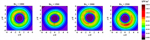
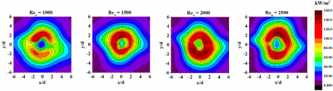
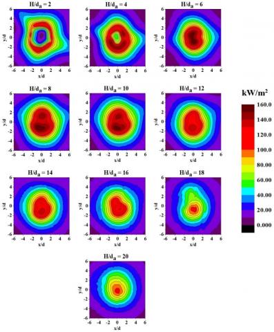
The heat flux contours of the coaxial inverse diffusion flame without and with swirl for varying Rea, ϕ =1.1 and H/da= 4 are shown in the Figures 2 and 3 respectively. Lower heat flux near the stagnation region is observed in case of without swirl IDF impingement for all the Reynolds number. This is due to an impingement of the air jet core at the stagnation region. When the swirl is provided in the flame jet, there is a drastic increase in the heat flux at the stagnation region due to the better mixing of air and fuel created by the swirl. The two peak heat fluxes lobes are observed on the target plate in case of the swirling impingement and is due to the splitting of the flame due to the present of twisted tape in the air jet tube. Figures 4 and 5 represents the heat flux contours on the target plate for without and with swirl, for varying H/da, Rea =2000 and ϕ =1.1 respectively. In case of without swirl, an increase in the H/da shifts the peak heat flux in the wall jet region to the stagnation region and reaches maximum at H/da =10. This is due to an impingement of the premixed part of the flame where the temperature is highest. In case of swirling IDF impingement (See Figure 5), the peak heat fluxes are started to observe from H/da=6 in the stagnation zone and is mainly due to the shortening of flame height due to swirl [10].
Figure 2. Heat flux contours for different Rea, without swirl at ϕ= 1.1 and H/da=4
Figure 3. Heat flux contours for different Rea, with swirl at ϕ = 1.1 and H/da=4
Figure 4. Heat flux contours for different H/da, without swirl at ϕ= 1.1 and Rea=2000
3.2 Average heat flux and peak heat flux
The results of swirling inverse diffusion flame are compared with that of non-swirling IDF (Without inserting twisted tape in the air jet tube). A comparison is made in terms of average heat flux ($\overline{\mathrm{q}}^{\prime \prime}$) defined by an Eq. (5) and the peak heat flux for the region 0<r/da<3 on an impingement plate.
$\bar{q}^{\prime \prime}=\frac{\sum_{i=1}^{N} q_{i}^{\prime \prime}}{N}$ (5)
where, N is the total number of heat flux data points on the impingement plate.
3.2.1 Effect of Reynolds number
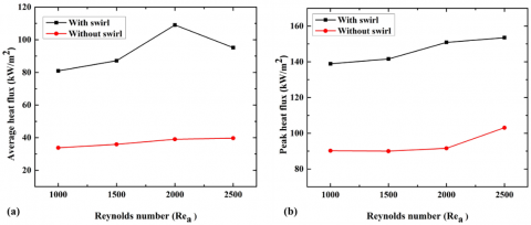
The average and peak heat flux values for the different air jet Reynolds number is shown in the Figure 6(a) and (b) respectively at ϕ= 1.1 and H/da=4. There is an enhancement of 139.33, 142.71, 179.20 and 139.68% in the average heat flux in the region 0<r/da<3 at Rea=1000-2500 as presented in Figure 6(a). Further it is seen that the highest average heat flux is at Rea=2000 for the swirl condition. The reason for this is the greater interaction of air and fuel and also entrainment of ambient air leads to the complete combustion of fuel at ϕ= 1.1. The Figure 6(b) shows the 53.95, 57.31, 64.73 and 48.90% increase in the peak heat flux. The peak heat fluxes are found to be the highest for the swirl conditions and is due to the premixed mode of flame impingement which has a highest flame temperature.
3.2.2 Effect of burner to target plate distance
Figure 7(a) and (b) shows an effect of burner-to-target surface distance on the heat flux at ϕ = 1.1 and Rea= 2000. An augmentation of average heat flux is found by 139.84, 179.20, 144.96, 74.29, 20.33, 8.20, 3.35 and 0.74 % for the H/da = 2 to 16 in comparison with non-swirling IDF impingement as shown in the Figure 7(a). The average heat flux in case of the swirling IDF, first increases up to H/da = 8 and then drops as an impingement plate moves away from the burner. It is due to an impingement of premixed flame region (reaction zone), where the temperature is highest. There is a drop in the average heat flux for the H/da=10 to 20. This is due to an impingement of the post combustion zone of IDF, where the temperature of the flame is lower and is diluted by an atmospheric air.
Figure 5. Heat flux contours for different H/da, with swirl at ϕ= 1.1 and Rea=2000
Figure 6. Comparison of average heat flux (a) and peak heat flux (b) for with swirl and without swirl coaxial burner for different Rea, ϕ= 1.1 and H/da=4
Figure 7. Comparison of average heat flux (a) and peak heat flux (b) for with and without swirl coaxial burner for different H/da, ϕ= 1.1 and Rea=2000
The peak heat flux is also found highest at the H/da=8 and is again due an impingement of premixed part of the flame. A reduction of 23.40% and 26.67% in the average heat flux and a reduction of 4.10% and 4.6% of peak heat flux is seen for the H/da= 18 to 20 respectively as compared to without swirl impingement and is shown in the Figure 7(a) and (b). The cause for this is that the swirling IDF does not touch to an impingement plate due to shortening of the flame height.
The experiments are conducted to examine the heat transfer characteristics of a coaxial IDF tube burner for with and without swirl conditions. An effect of the air jet Reynolds number (Rea) and distance between the burner to target surface (H/da) on the heat flux average and peak heat flux of the swirling IDF is compared with that of non-swirl IDF. The subsequent conclusions are made.
1) Lower heat flux near the stagnation region is observed for the non-swirling IDF impingement due to the touching of air jet core. However, there is an improvement in the flux when the air jet core is destroyed by the swirl.
2) The comparison of average heat flux of the swirling and non-swirling IDF for the different air jet Reynolds number reveals that the swirling IDF promotes the better combustion due to rapid mixing of air and fuel. At ϕ = 1.1, H/da = 4, the swirling flame obtained a maximum average heat flux of 179.2% for Rea=2000 when compared to non-swirling IDF even though the mixture is richer.
3) At Rea = 2000 and ϕ = 1.1, the experiments conducted for different H/da of 2 to 20, the maximum heat transfer is obtained at H/da = 8 for swirling and H/da = 10 for non-swirling condition. For this operating condition, swirling IDF attained a better average heat flux than that of non-swirling IDF. However, an average heat flux decreases for the H/da = 18 to 20 for the swirling IDF due to the shorter flame height.
|
Symbol |
|
|
Rea |
Reynolds number of air jet |
|
$\dot{\mathrm{m}}_{\mathrm{a}}$ |
Mass flow rate of air (kg/s) |
|
da |
Diameter of air jet (m) |
|
k |
Thermal conductivity (W/m k) |
|
q" |
Heat flux (W/m2) |
|
t |
Time (sec) |
|
T |
Temperature (K) |
|
Z |
Quartz plate thickness (mm) |
|
p |
Twisted tape pitch (mm) |
|
w |
Twisted tape width (mm) |
|
S |
Swirl number |
|
Greek symbols |
|
|
a |
Thermal diffusivity (m2/s) |
|
ϕ |
Equivalence ratio |
|
µ |
Absolute viscosity of air (Pa-s) |
|
Subscription |
|
|
stoic |
Stoichiometric |
|
act |
Actual |
|
i |
Initial |
|
- |
Average |
|
a |
Analytical |
|
e |
Experimental |
|
Abbreviations |
|
|
A |
Air |
|
F |
Fuel |
|
IDFs |
Inverse diffusion flames |
|
H |
Distance between burner surface to target plate (m) |
[1] Sze, L.K., Cheung, C.S., Leung, C.S. (2006). Appearance, temperature, and NOx emission of two inverse diffusion flames with different port design. Combustion and Flame, 144(1-2): 237-248. https://doi.org/10.1016/j.combustflame.2005.07.008
[2] Mikofski, M.A., Williams, T.C., Shaddix, C.R., Belvins, L.G. (2006). Flame height measurement of laminar inverse diffusion flames. Combustion and Flame, 146(1-2): 63-72. https://doi.org/10.1016/j.combustflame.2006.04.006
[3] Mahesh, S., Mishra, D.P. (2008). Flame stability and emission characteristics of turbulent LPG IDF in a backstep burner. Fuel, 87(12): 2614-2619. https://doi.org/10.1016/j.fuel.2008.02.001
[4] Mahesh, S., Mishra, D.P. (2010). Flame structure of LPG-air Inverse Diffusion Flame in a backstep burner. Fuel, 89(8): 2145-2148. https://doi.org/10.1016/j.fuel.2010.01.030
[5] Zhen, H.S., Choy, Y.S., Leung, C.W., Cheung, C.S. (2011). Effect of nozzle length on flame and emission behaviors of multi-fuel-jet inverse diffusion flame burner. Applied Energy, 88(9): 2917-2924. https://doi.org/10.1016/j.apenergy.2011.02.040
[6] Dong, L.L., Cheung, C.S., Leung, C.W. (2011). Combustion optimization of a port array inverse diffusion flame jet. Energy, 36(5): 2834-2846. https://doi.org/10.1016/j.energy.2011.02.025
[7] Choy, Y.S., Zhen, H.S., Leung, C.W., Li, H.B. (2012). Pollutant emission and noise radiation from open and impinging inverse diffusion flames. Applied Energy, 91(1): 82-89. https://doi.org/10.1016/j.apenergy.2011.09.013
[8] Miao, J., Leung, C.W., Cheung, C.S., Huang, Z.H., Zhen, H.S. (2016). Effect of hydrogen addition on overall pollutant emissions of inverse diffusion flame. Energy, 104: 284-294. https://doi.org/10.1016/j.energy.2016.03.114
[9] Cha, M.S., Son, J.W., Yoon, S.H., Luong, H.T., Lacoste, D.A., Sohn, C.H. (2019). Vortex formation mechanism within fuel stream in laminar nonpremixed jet flames. Combustion and Flame, 199: 46-53. https://doi.org/10.1016/j.combustflame.2018.10.015
[10] Zhen, H.S., Leung, C.W., Cheung, C.S. (2010). Thermal and emission characteristics of a turbulent swirling inverse diffusion flame. International Journal of Heat and Mass Transfer, 53(5): 902-909. https://doi.org/10.1016/j.ijheatmasstransfer.2009.11.034
[11] Kotb, A., Saad, H. (2016). A comparison of the thermal and emission characteristics of co and counter swirl inverse diffusion flames. International Journal of Thermal Sciences, 109: 362-373. https://doi.org/10.1016/j.ijthermalsci.2016.06.015
[12] Patel, V., Shah, R. (2018). Experimental investigation on flame appearance and emission characteristics of LPG inverse diffusion flame with swirl. Applied Thermal Engineering, 137: 377-385. https://doi.org/10.1016/j.applthermaleng.2018.03.105
[13] Patel, V., Shah, R. (2019). Effect of swirl and number of swirler vanes on combustion characteristics of methane inverse diffusion flame. Journal of Mechanical Science and technology, 33(4): 1947-1958. https://doi.org/10.1007/s12206-019-0345-7
[14] Rabee, B.A. (2018). The effect of inverse diffusion flame burner-diameter on flame characteristics and emissions. Energy, 160: 1201-1207. http://doi.org/10.1016/j.energy.2018.07.061
[15] Patel, V., Shah, R. (2019). Analysis of LPG diffusion flame in tube type burner. Journal of Mechanical Engineering and Science, 13(3): 5278-5293. https://doi.org/10.15282/jmes.13.3.2019.05.0431
[16] Tong, Y., Liu, X., Wang, Z., Richter, M., Klingmann, J. (2018). Experimental and numerical study on bluff body and swirl stabilized diffusion flames. Fuel, 217: 352-364. https://doi.org/10.1016/j.fuel.2017.12.061
[17] Zhao, Z., Yuen, D.W., Leung, C.W., Wong, T.T. (2009). Thermal performance of a premixed impinging circular flame jet array with induced-swirl. Applied Thermal Engineering, 29(1): 159-166. https://doi.org/10.1016/j.applthermaleng.2008.02.016
[18] Hindasageri, V., Vedula, R.P., Prabhu, S.V. (2015). Heat transfer distribution of swirling flame jet impinging on a flat plate using twisted tape. International Journal of Heat and Mass Transfer, 91: 1128-1139. https://doi.org/10.1016/j.ijheatmasstransfer.2015.08.038
[19] Kumar, S.S., Hindasageri, V., Prabhu, S.V. (2017). Local heat transfer distribution on a flat plate impinged by a swirling jet generated by a twisted tape. International Journal of Thermal Sciences, 111: 351-368. https://doi.org/10.1016/j.ijthermalsci.2016.09.009
[20] Kuntikana, P. Prabhu, S.V. (2017). Effect of mixture composition on heat transfer characteristics of impinging methane-air flame jets of tube burner equipped with twisted tapes. International Journal of Thermal Sciences, 111: 409-422. https://doi.org/10.1016/j.ijthermalsci.2016.09.024
[21] Singh, P., Chander, S. (2019). Study of flow field and heat transfer characteristics for an interacting pair of counter-rotating dual-swirling impinging flames. International Journal of Thermal Sciences, 144: 191-211. https://doi.org/10.1016/j.ijthermalsci.2019.06.005
[22] Sze, L.K., Cheung, C.S., Leung, C.W. (2004). Temperature distribution and heat transfer characteristics of an inverse diffusion flame with circumferentially arranged fuel ports. International Journal of Heat and Mass Transfer, 47(14): 3119-3129. https://doi.org/10.1016/j.ijheatmasstransfer.2004.02.015
[23] Dong, L.L., Cheung, C.S., Leung, C.W. (2013). Heat transfer optimization of an impinging port-array inverse diffusion flame jet. Energy, 49(1): 182-192. https://doi.org/10.1016/j.energy.2012.10.041
[24] Dong, L.L., Cheung, C.S., Leung, C.W. (2013). Characterization of impinging region from an impinging inverse diffusion flame jet. International Journal of Heat and Mass Transfer, 56(1-2): 360-369. https://doi.org/10.1016/j.ijheatmasstransfer.2012.08.064
[25] Zhen, H.S., Leung, C.W., Cheung, C.S. (2011). A comparison of the thermal, emission and heat transfer characteristics of swirl-stabilized premixed and inverse diffusion flames. Energy Conversion and Management, 52(2): 1263-1271. https://doi.org/10.1016/j.enconman.2010.09.023
[26] Zhen, H.S., Cheung, C.S., Leung, C.W., Li, H.B. (2013). Thermal and heat transfer behaviors of an inverse diffusion flame with induced swirl. Fuel, 103: 212-219. https://doi.org/10.1016/j.fuel.2012.05.026
[27] Hindasageri, V., Vedula, R.P., Prabhu, S.V. (2015). Heat transfer distribution for three interacting methane -air premixed impinging flame jets. International Journal of Heat and Mass Transfer, 88: 914-925. https://doi.org/10.1016/j.ijheatmasstransfer.2015.04.098
[28] Hindasgeri, V., Kuntikana, P., Vedula, R.P., Prabhu, S.V. (2015). An experimental and numerical investigation of heat transfer distribution of perforated plate burner flames impinging on a flat plate. International Journal of Thermal Sciences, 94: 156-169. https://doi.org/10.1016/j.ijthermalsci.2015.02.021
[29] Badiger, S., Anil, T.R., Hindasageri, V., Katti, V.V. (2020). Heat transfer characteristics of an inverse diffusion flame with induced swirl. Journal of the Brazilian Society of Mechanical Sciences and Engineering, 42: 252. https://doi.org/10.1007/s40430-020-02330-5
[30] Moffat, R.J. (1985). Using uncertainty analysis in the planning of an experiment. Journal of Fluids Engineering, 107(2): 173-178. https://doi.org/10.1115/1.3242452