Syaiful* | Arsanti Rakha Siwi | Tony Suryo Utomo | Yurianto | Retno Wulandari
© 2019 IIETA. This article is published by IIETA and is licensed under the CC BY 4.0 license (http://creativecommons.org/licenses/by/4.0/).
OPEN ACCESS
This study is intended to analyze numerically and experimentally the characteristics of heat transfer augmentation and pressure drop of airflow through vortex generators mounted to a heated plate inside a rectangular channel. Delta winglet pairs (DWPs) and concave delta winglet pairs (CDWPs) vortex generators (VGs) with one, two, and three rows were used in this study. Heat transfer enhancement and pressure drop of flow passing through the VGs with a 5 mm diameter hole for one, two, and three holes in certain positions were investigated. VGs were mounted in-line with an attack angle of 15° to the flow. The airflow was assumed to be incompressible; the steady-state and air velocity were varied in the range of 0.4 m/s to 2 m/s. The analysis showed that the use of holes in the delta winglet vortex generators could reduce the pressure drop of 34.14% from the delta winglet without holes at a velocity of 2 m/s. By using perforated delta (DWP VGs) and concave delta winglet (CDWP VGs), the heat transfer coefficient is reduced by 1.81% and 7.03% of the delta and concave delta winglet vortex generators without holes at a velocity of 2 m/s.
convection heat transfer coefficient, pressure drop, perforated concave delta winglet vortex generators
Several studies have been conducted on various HTE (Heat Transfer Enhancements) technologies with the aim of improving the performance of heat exchangers and reducing the cost of heat exchanger designs. Heat transfer augmentation on fin-and-tube can be done by extending the fin or by enhancing the convection heat transfer coefficient. Because of the high thermal resistance of the airside between the fins resulting in a low rate of heat transfer, an improvement in the heat transfer coefficient is required to reduce thermal resistance so that the rates of heat transfer from the fin surface to the air increases. Increased heat transfer rates have an impact on increasing efficiency, low manufacturing costs, small volumes, and lightweight of heat exchangers [1]. An increase in heat transfer can be performed one way by using a vortex generator.
Various studies have been carried out regarding vortex generators in heat exchangers. Fiebig [2] conducted experiments and simulations of vortex generators of wing and winglet types. The analysis proves that winglet VG is more effective in increasing heat transfer than the wing with a lower pressure drop. Gholami et al. [3] examined the increase of heat transfer and pressure drop in fin-tube heat exchangers with VG wavy rectangular winglets. The results of their study indicated that wavy rectangular winglets could significantly increase heat transfer in the fin-tube heat exchanger. Du et al. [4] investigated numerically and experimentally on delta wing, rectangular wing, delta winglet pairs, and rectangular winglet pairs vortex generators with variations in angle of attack of 10°, 20°, 25° with velocities from 1 m/s to 5 m/s in wavy finned tube. The results of their study stated that the delta winglet pairs with an attack angle of 25° are the best configuration to increase the air-side heat transfer between the types of vortex generators tested. Grag and Dhingra [5] performed numerical simulations on triangular ribbed channels using winglet vortex generators with several variations of angle of attack in turbulent air-flow. From their work, it was found that it was observed an increase in the rate of heat transfer of 80%, 85%, and 90% compared without using a vortex generator at angles of attack of 30°, 45°, and 60°, respectively. Li et al. [6] conducted a numerical simulation study using longitudinal vortex generators of rectangular winglet and delta winglet types with several variations of angle of attack on the fin-tube heat exchanger. The results show that the rectangular winglet is better at increasing the heat transfer rate compared to the delta winglet at the same angle of attack. In addition, Ebrahimi et al. [7] performed numerical simulations using winglet vortex generators with various shapes and angles of attack on the rectangular heat sink. They found that rectangular vortex generators can increase heat transfer rates better than trapezoidal vortex generators (TVG) and delta vortex generators (DVG). Lin et al. [8] numerically analyzed tubes with the twisted-parallelogram winglets (PWVGs) vortex generators inserted in them. The results of their analysis proved that PWVGs could produce secondary flow, which can increase heat transfer with a low increase in pressure loss compared to other types of VGs in various Reynolds numbers. In all Reynolds numbers, longitudinal vortices are more effective than transverse vortices. Lu and Zhou [9] numerically examined several types of vortex generators, namely: rectangular winglets, trapezoidal winglets, delta winglets, curved rectangular winglets, curved trapezoidal winglets, curved delta winglets in a rectangular channel with variations in attack angles of 0°, 30°, 45° and 60°. The results showed that curved trapezoidal winglets with a 45° attack angle provide the best results in enhancing heat transfer. Oneissi et al. [10] performed numerical simulations using inclined projected winglet pair (IPWP) and delta winglet pair (DWP) on the plate-fin heat exchanger. From the results of their investigations, it can be stated that the inclined projected winglet pair (IPWP) has a slightly better ability to increase the rate of heat transfer compared to the delta winglet pair (DWP). Dezan et al. [11] performed numerical simulations on flat-tube multi louvered fin compact heat exchangers using a delta winglet vortex generator. Their work showed that the increase in heat transfer of 21.27% was found with a pressure drop of 24.66% at Re=120, whereas at Re=240, there was an increase in heat transfer of 23.52% and an increase in pressure drop of 36.67%.
Saha et al. [12] performed numerical simulations on rectangular winglet pair (RWP) and delta-winglet pair (DWP) vortex generators that are installed with common-flow-up (CFU) and common-flow-down (CFD) orientations. Their simulation results showed that RWP VGs increase heat transfer higher than DWP VGs in both CFU and CFD installation orientations. Xu et al. [13] experimentally investigated the thermal performance and flow behavior with a winglet vortex generator inserted in a circular pipe. The results of their study indicated that the best increase in heat transfer occurs at an angle of attack of 30° and a ratio of B = 0.1. In addition, Song et al. [14] carried out experimentally with compact circular tube-and-fin heat exchangers by adding vortex generators of the curved delta winglet type and varying fin distances to improve heat transfer performance. They found that small size vortex generators placed close to the tube can effectively increase heat transfer for low Reynolds numbers, whereas large size vortex generators are more conducive to high Reynolds numbers. Curved delta winglet VGs can effectively improve heat transfer performance at the fin.
In the previous study, Syaiful et al. [15] numerically investigated the effect of heat transfer rates on a channel using delta winglet pair (DWP) and concave delta winglet pair (CDWP) vortex generators. This numerical simulation was done with/without VGs (baseline), then the air flowed at velocities in the range of 0.4 m/s to 2 m/s at an angle of attack of 30° with one, two, and three pairs of VGs. From this study, it was found that three pairs of delta winglets and concave delta winglets were able to increase heat transfer by 69.6% and 96% to the baseline, respectively. Syaiful et al. [16] studied the effect of concave delta winglet VGs on the improvement of heat transfer in the fin-and-tube heat exchanger for EGR cooler application. They found that the heat transfer coefficient was enhanced by 30% against the baseline using delta winglet (DW) VGs at an attack angle of 20° and 35.6% with concave delta winglet (CDW) VG at an angle of attack of 15°. They also found an increase in pressure drop of 35.5% and 66.1% of the baseline at 20° attack angles with the use of DW and CDW VGs, respectively. In the following year, Syaiful et al. [17] try to evaluate the effect of rectangular concave winglet vortex generators (CRW VGs) on the convection heat transfer coefficient in a rectangular channel experimentally. By using CRW VGs with an attack angle of 30°, the dimensionless heat transfer coefficient was increased by 205%. At the same time, Syaiful et al. [18] study experimentally and numerically the effect of using CDW VG on thermal performance and hydrodynamic of fluid flow in a channel. They observed that the heat transfer coefficient increases to 110.7%, with a pressure drop increase of 266.9% against the baseline using three pairs of CDW VGs. Syaiful et al. [19] experimentally evaluate the perforated DW VGs effect on the pressure drop flow in a rectangular channel. Their results show that the convection coefficient increases by 78.9% compared to baseline, and pressure loss decreases 35.37% compared to the vortex generator without a hole. Therefore, the current study focuses more on the characteristics of fluid passing through perforated CDW VGs in a rectangular channel using numerical simulations.
2.1 Physical model
Geometry and boundary conditions in this study refer to physical phenomena based on previous experiments [19]. Experiments were carried out to determine the thermal and hydrodynamic performance of the flow through a rectangular channel with the installation of a vortex generator. Vortex generators used in the experiment were perforated delta winglet (DWP) and concave delta winglet pairs (CDWP) with a diameter of 5 mm at an angle of attack of 15°. In this investigation, vortex generators were mounted with one, two, and three pairs with one, two, and three holes in the VGs. In experiments, air at ambient temperature was flowed inside a rectangular channel at variations in velocity from 0.4 m/s (Re=1,600 for laminar flow) to 2 m/s (Re=8,600 for turbulent flow) with intervals of 0,2 m/s. Experimental results were used as a reference for numerical simulations on laminar and turbulent models such as the inlet velocity, the inlet air temperature at atmospheric pressure, and the temperature of the heated wall.
2.2 Governing equations
In the current study, the air was assumed to be incompressible with constant physical properties. Simulations were carried out in a steady state. Two models of laminar and turbulent flow were simulated in this work. The temperature distribution on the surface of the heating plate can be known by solving conjugate heat transfer problems into calculations on the computational domain.
The governing equations used to solve this case are
$\frac{\partial}{\partial x_{i}}\left(\rho u_{i}\right)=0$ (1)
$\frac{\partial}{\partial x_{i}}\left(\rho u_{i} u_{k}\right)=\frac{\partial}{\partial x_{i}}\left(\mu \frac{\partial u_{k}}{\partial x_{i}}\right)-\frac{\partial p}{\partial x_{k}}$ (2)
$\frac{\partial}{\partial x_{i}}\left(\rho u_{i} T\right)=\frac{\partial}{\partial x_{i}}\left(\Gamma \frac{\partial \mathrm{T}}{\partial \mathrm{x}_{\mathrm{i}}}\right)$ (3)
where, $\rho$ and $\mu$ are the density and dynamic viscosity of air, respectively. Whereas $\Gamma$ denotes diffusion coefficient, $\Gamma=\lambda / \mathrm{Cp}$ where, $\lambda$ and $C p$ are thermal conductivity and air specific heat, respectively. The turbulent flow was modeled using the standard $k-\omega$ model, as shown in Eqns. (4) and (5) [ 20].
$\frac{\partial}{\partial x_{i}}\left(\rho k u_{i}\right)=\frac{\partial}{\partial x_{j}}\left(\Gamma_{k} \frac{\partial k}{\partial x_{j}}\right)+G_{k}-Y_{k}+S_{k}$ (4)
$\frac{\partial}{\partial x_{i}}\left(\rho \omega u_{i}\right)=\frac{\partial}{\partial x_{j}}\left(\Gamma_{\omega} \frac{\partial \omega}{\partial x_{j}}\right)+G_{\omega}-Y_{\omega}+S_{\omega}$ (5)
where,
$\Gamma_{k}=\mu+\frac{\mu_{t}}{\sigma_{k}}$ (6)
$\Gamma_{\omega}=\mu+\frac{\mu_{t}}{\sigma_{\omega}}$ (7)
Turbulent intensity is defined as
$I=0.16 R e_{D_{h}}^{-1 / 8}$ (8)
2.3 Boundary conditions
The boundary conditions in the inlet, outlet, symmetry, and hot wall are as follows:
$u=u_{i n}, v=w=0, T=T_{i n}$ (9)
$\frac{\partial u}{\partial x}=\frac{\partial v}{\partial x}=\frac{\partial w}{\partial x}=\frac{\partial T}{\partial x}=0$ (10)
$u=v=w=0, q=0$ (11)
$u=v=w=0, T=T_{w}$ (12)
$w=0, \frac{\partial u}{\partial y}=\frac{\partial w}{\partial y}=\frac{\partial T}{\partial y}=0$ (13)
3.1 Geometry and computational domain
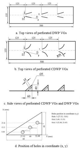
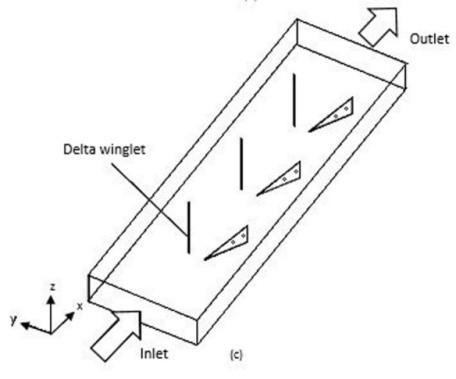
The geometry and coordinate systems used in this study are shown in Figure 1, respectively. The X-axis is the axis in the direction of flow, the Y-axis is the transverse axis of the flow, and the Z-axis is the distance between the upper wall and the lower wall. The computational domain of this numerical simulation is shown in Figure 2. The dimensions of a rectangular channel on the computational domain of numerical simulation are 500 mm x 155 mm x 43 mm. While the dimensions of DWP and CDWP VGs with a diameter of each hole of 5 mm at the angle of attack of 15° is 60 mm x 1 mm x 27 mm, but CDWP has a surface curvature radius of 58 mm [15]. The computational domain of this numerical simulation is a control volume, which is half the volume of the geometry of a rectangular channel. Computation domains consist of inlet and outlet extended regions, which are an extension of the inlet and outlet sides (upstream and downstream extended regions). The extended regions are required to ensure the fully developed flow at the entrance of the test plate, and there is no reverse flow in the exit side.
Figure 1. Detail geometry and size of perforated DWP and CDWP VGs
Figure 2. Computational domain of numerical simulation
3.2 Numerical simulation
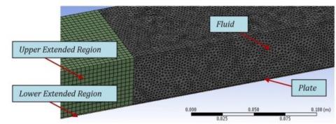
The simulation for 3D VGs on the fin and tube heat exchanger is very complex, and accuracy is needed in mesh generation to obtain good results in determining the velocity and temperature distribution. Mesh generation cannot be performed using just one type of mesh for each part of the computation domain. Therefore, the hexahedral mesh was used in the upstream and downstream extended region, while tetrahedral mesh was used for the fluid and plate region because of the complexity of the vortex generator, as shown in Figure 3. Inflation mesh was used in fluid regions and vortex generator walls because of the need for the finer mesh.
Figure 3. Mesh generation
The governing equation for momentum, energy, turbulent kinetic energy, specific dissipation rate, momentum thickness was discretized by a second-order upwind scheme. Pressure-velocity coupling was calculated using the SIMPLE algorithm. The viscous model used in this numerical modeling was laminar for laminar flow and k-ω model for turbulent flow. The residual convergence criteria were 10-5 for momentum and velocity, 10-8 for energy, and 10-6 for k and ω.
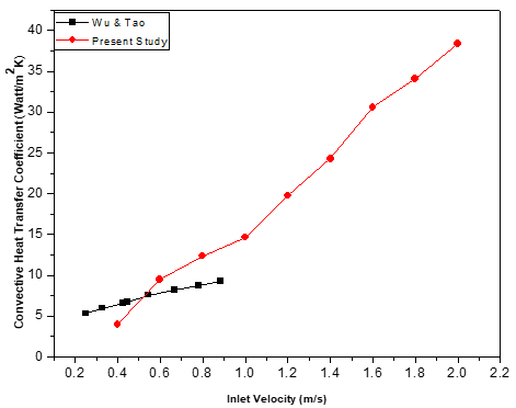
3.3 Validation
The independence grid test was done to get the optimum grid number. This independent grid test was carried out on four different grid numbers ranging from 1,200,000 to 1,800,000 with the computational domain of the three pairs of concave delta winglet (CDWPs) VGs. Numerical calculations were carried out on each number of grids to obtain the convection heat transfer coefficient at the inlet velocity of 0.4 m/s. Because of the small difference in the value of the heat transfer coefficient from the simulation results for the four grid numbers, then the optimum number of grids used in numerical calculations was found by determining the lowest error from comparing the heat transfer coefficient values of the simulation and experiment results as shown in Table 1. From these results, it was found that the number of grids of 1,661,610 was the optimum grid.
Table 1. Independent grid test
|
Number of grid |
Heat transfer coefficient (simulation) |
Heat transfer coefficient (experiment) |
Deviation (%) |
|
1.262.840 |
18,28 |
18,186 |
0,503 |
|
1.478.060 |
18,35 |
0,891 |
|
|
1.661.610 |
18,25 |
0,337 |
|
|
1.868.587 |
18,29 |
0,597 |
Figure 4. Comparison of heat transfer coefficient between current experiment and Wu and Tao’s experiment
3.4 Parameters definition
Reynolds number (Re) and average Nusselts number ((Nu) ̅), friction factor (f) and Colburn factor (j) are stated as follows:
$R e=\frac{\rho u_{i n} D_{h}}{\mu} \overline{N u}=\frac{h D_{h}}{\lambda}$ (14)
$f=\frac{2 \Delta P D_{h}}{\rho u_{i n}^{2} L} j=\frac{\overline{N u}}{R e P r^{1 / 3}}$ (15)
where, $u_{i n}, \mu,$ and $D_{h}$ are density, fluid velocity in x-direction, dynamic viscosity, and hydraulic diameter, respectively. Meanwhile, $\lambda$ is fluid thermal conductivity, and $h$ is the convection heat transfer coefficient. Total heat transfer, the pressure drop between the inlet and outlet sides of the test plate are defined as follows:
$Q=\dot{m} c_{p}\left(\bar{T}_{o u t}-\bar{T}_{i n}\right)$ (16)
$\Delta P=\bar{P}_{i n}-\bar{P}_{o u t}$ (17)
The heat transfer coefficient is formulated as follows:
$h=\frac{Q}{A\left(T_{w}-T_{f}\right)}$ (18)
where, $Q$ and $A$ are the rate of convection heat transfer and the heat transfer surface area, respectively. $T_{w}$ is a hot wall temperature, while $T_{f}$ is a fluid bulk temperature $\left(T_{i n}+T_{\text {out}}\right) / 2$
4.1 Flow field in cross-section planes
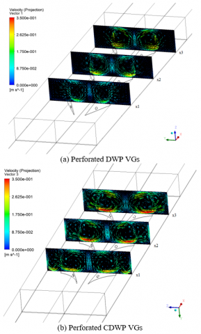
Figure 5 shows the cross-section of the velocity vector through three pairs of perforated DW and CDW VGs at a flow velocity of 0.4 m/s. From Figure 5, it is found that the longitudinal vortex generated by CDWP VGs has a larger radius and higher velocity than that of the DWP VGs. Corner vortex is also observed when the flow passes CDWP VGs. The orientation of the installation of VGs with a common flow-up configuration causes counter-rotating longitudinal vortices [21]. Counter-rotating longitudinal vortices are found in the wake region of the VG with the flow going in the downwash region in the opposite direction. The effect of the VG shape results in the longitudinal vortex radius generated by the CDWP VG being greater than that of the DWP VG due to the instability of the centrifugal force [22]. This results in a penetration away from the longitudinal vortex into the wake region, which causes good fluid mixing [7]. This phenomenon is also found in the results of a study by Lu et al. [9] with a curved VG. X1, X2, and X3 are cross-section positions at 175 mm, 300 mm and 450 mm, respectively.
Figure 5. Velocity vector in cross-section planes at certain locations for perforated DWP and CDWP VGs
4.2 Intensity of longitudinal vortex
In order to understand the longitudinal vortex structure generated by the vortex generator, a non-dimensional parameter called the longitudinal vortex intensity [9, 23] is defined as expressed by Eq. (19):
$\Omega_{x}=\frac{\omega_{x} D_{h}}{\bar{U}}$ (19)
where, wx is vorticity given by:
$\omega_{x}=\frac{\partial w}{\partial y}-\frac{\partial v}{\partial z}$ (20)
where, $\bar{U}$ is the free stream fluid velocity and $D h$ is the hydraulic diameter.
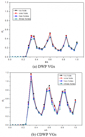
Figure 6. Comparison of longitudinal vortex intensity between DWP and CDWP VGs with/without holes at the inlet velocity of 0.4 m/s
Figures 6 (a) and (b) show the longitudinal vortex intensity for three pairs of DW and CDW VGs, respectively, at a velocity of 0.4 m/s. From these two figures, it is obviously revealed that longitudinal vortices form after fluid passes through VGs. This is evidenced by the value of maximum longitudinal vortex intensity at x/L=0.32, 0.6, and 0.84 in the case of DWP VGs where those locations are behind VGs as denoted in Figure 6(a). It is also found that the highest value of longitudinal vortex intensity is observed for the use of DWP VGs without holes at locations x/L=0.36, 0.6, and 0.84. The high value of the longitudinal vortex intensity indicates the high vorticity of longitudinal vortices generated by VGs. A similar tendency, as revealed in Figure 6(a), is found in the case of CDWP VGs. The highest longitudinal vortex intensity values are observed at x/L=0.32, 0.6, and 0.8, where these locations are placed behind VGs. By comparing Figures 6 (a) and (b), it is observed that the longitudinal vortex intensity generated by CDWP VGs is higher than that generated by DWP VGs at the same location. This is due to the presence of centrifugal force when the fluid passing through the concave surface [18, 22] results in a stronger longitudinal vortex, which has an impact on the high value of longitudinal vortex intensity. From Figure 6(b), it is also found that the peak value of the longitudinal vortex intensity in the streamwise decreases. This indicates a weakening of longitudinal vortices, which is probably due to the increase in drag. Figure 6 also informs that the addition of the hole with the same diameter slightly decreases the value of the longitudinal vortex intensity for the same location for both DWP and CDWP VGs. The jet from the hole increases the kinetic energy level [24], resulting in a decreasing velocity gradient so that decreased vorticity causes a decrease in the value of the longitudinal vortex intensity. In the case of DWP VGs, the addition of three holes in VG result in a decrease in longitudinal vortex intensity up to 18.1% at the location of x/L=0.6. Longitudinal vortex intensity is decreased by 15% with the addition of three holes in CDWP VGs at location x/L=0.32.
4.3 Temperature distribution in cross-section planes
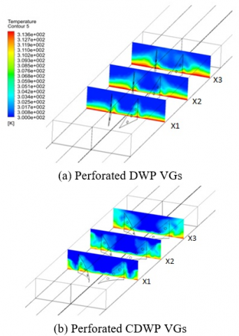
Figure 7 shows the temperature distribution in the cross-section plane at several locations for the installation of three-perforated VGs at a flow velocity of 0.4 m/s. From Figure 7, it is found that the longitudinal vortex affects the temperature distribution in the cross-section planes of the main flow. Overall, the temperature distribution for the CDWP VGs case is better than for the DWP VGs case, as shown in Figure 7. This is because the longitudinal vortex formed from CDWP VGs is stronger than the longitudinal vortex formed from DWP VGs [15]. Longitudinal vortex causes improved heat transfer due to better mixing of the hot fluid near the wall with the fluid in the main flow. Longitudinal vortex causes the boundary layer to thin out [15]. This results in increased heat transfer in the region around the VG [25].
Figure 7. Temperature distribution in cross-section planes at certain locations for DWP and CDWP VGs
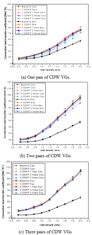
4.4 Effect of perforated delta winglet vortex generators on heat transfer enhancement
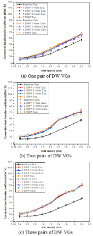
Figures 8 and 9 show the convection heat transfer coefficient value with various numbers of DW and CDW VGs pairs and the number of holes in the variation of the inlet air velocity. The convection heat transfer coefficient increases with increasing airflow velocity. The higher flow velocity causes higher turbulent intensity resulting in better mixing of the flow and enhancing heat transfer [13, 26]. From Figures 8 and 9, it can also be concluded that the impact of the hole on VGs on the heat transfer rate is very small. This is in accordance with one of the objectives to be achieved in this study. By comparing the values of convection heat transfer coefficients between the simulation and experimental results, there are very small differences with the same tendency. At a flow velocity of 2 m/s, the calculation results found that the use of CDWP VGs can enhance the heat transfer rate up to 47.37% higher than the use of DWP VGs.
Figure 8. Convection heat transfer coefficient for DW VGs with different number of pair and hole in variations of inlet velocities
Figure 9. Convection heat transfer coefficient for CDW VGs with different number of pair and hole in variations of inlet velocities
4.5 Effect of vortex generator on synergy angle
The field synergy principle (FSP) is a method for analyzing the enhancement of heat transfer in the flow in the presence of temperature gradient. This method was first introduced by Guo et al. [27]. This method begins with the idea that convection heat transfer is essentially conductive heat transfer under fluid motion. This explanation can be expressed in Eq. (21):
$\rho c_{p}\left(u \frac{\partial T}{\partial x}+v \frac{\partial T}{\partial y}\right)=\frac{\partial}{\partial y}\left(-k \frac{\partial T}{\partial y}\right)$ (21)
where, Eq. (21) is the energy balance in the boundary layer region. From this equation, it can be stated that the increase of heat flux by conduction on the surface results in an increase in the heat flux by convection in the flow. By integrating Eq. (21) as thick as the boundary layer produces:
$\int_{0}^{\delta_{t}} \rho c_{p}\left(u \frac{\partial T}{\partial x}+v \frac{\partial T}{\partial y}\right)=-k \frac{\partial T}{\partial y}$ (22)
Eq. (22) indicates that the improvement of heat transfer can be enhanced by raising the integral of its convective term on its thermal boundary layer [27]. This Eq. (22) can be written in vector form as expressed by Eq. (23):
$\rho c_{p} \int_{0}^{\delta_{t}}(\boldsymbol{U} \cdot \nabla \boldsymbol{T}) d y=-k \frac{\partial T}{\partial y}$ (23)
where, the physical properties of $\rho$ and $\mathrm{cp}$ are considered constant. By defining some dimensionless parameters such as
$U^{*}=\frac{U}{U_{\infty}} \quad \nabla T^{*}=\frac{\nabla T}{\left(T_{\infty}-T_{W}\right) / \delta_{t}} \quad y^{*}=\frac{y}{\delta_{t}} \quad T^{*}=\frac{T-T_{\infty}}{T_{W}-T_{\infty}}$
Eq. (23) can be expressed in the dimensionless form as shown in Eq. (24):
$\operatorname{Re}_{\mathrm{x}} \operatorname{Pr} \int_{0}^{1}\left(\mathrm{U}^{*} \cdot \nabla \mathrm{T}^{*}\right) \mathrm{d} \mathrm{y}^{*}=\mathrm{Nu}_{\mathrm{x}}$ (24)
By dividing Eq. ( 24) with $\operatorname{Re}_{x} P r,$ it is found the Stanton number (St), which is a modification of the Nusselt number, $S t=N u_{x} / R e_{x} P r,$ as can be expressed in Eq. ( 25):
$\int_{0}^{1}\left(\mathrm{U}^{*} \cdot \nabla \mathrm{T}^{*}\right) \mathrm{d} \mathrm{y}^{*}=\mathrm{St}$ (25)
Increased Stanton number means an increase in heat transfer. This increase in Stanton number can be performed by increasing the value $\mathrm{U}^{*} \cdot \nabla \mathrm{T}^{*} .$ This increase in the value of $\mathrm{U}^{*}$ $\nabla \mathrm{T}^{*}$ can be indicated by decreasing the angle between the velocity and the temperature gradient in the flow referred to as the synergy angle, as expressed in Eq. ( 26) :
$\boldsymbol{U}^{*} \cdot \nabla T^{*}=\left|\boldsymbol{U}^{*} \| \nabla T^{*}\right| \cos \theta$ or $\cos \theta=\frac{\boldsymbol{U}^{*} \cdot \nabla T^{*}}{\left|\boldsymbol{U}^{*} \| \nabla T^{*}\right|}$ (26)
where, $\theta$ is synergy angle.
Figure 10 shows the synergy angle along the surface of the plate for the case of DW and CDW VGs with variations in the number of pairs of VGs and the number of holes in VG at the fluid velocity of 0.4 m/s. In general, the use of vortex generators can increase the local heat transfer rate due to mixing flow with the presence of LVs. This can also be observed with low local synergy angle because the lower the synergy angle between the velocity vector and the temperature gradient indicates an increase in heat transfer as formulated in Eq. (26) [28]. From the results of a numerical analysis, it is observed that the value of the synergy angle in the wake region for the case of CDWP VGs is lower than for the case of DWP VGs. This indicates that CDWP VGs can increase heat transfer rates better than that of DWP VGs. Figures 10 (a) and (d) illustrate the synergy angle for one pair of DW and CDW VGs with/without holes, respectively. By comparing Figures 10 (a) and (d), it is observed that the lowest synergy angle is found at x/L> 0.3 for both DW and CDW VGs cases with/without holes. For the case of one pair of DW VGs, the lowest value of the synergy angle is found for VG without holes at x/L=0.4. This is in accordance with the convection heat transfer coefficient value of the experimental results shown in Figure 8 (a). Inconsistency is found in the simulation results where DW VGs without holes have a convection heat transfer coefficient slightly lower than the case with three holes. However, the prediction of the average convection heat transfer coefficient value may be valid because the synergy angle predicts an increase or decrease in heat transfer locally. A similar problem is found in the case of one pair of CDW VGs revealed in Figure 10 (d). In this case, the synergy angle value for CDW VGs without hole has the lowest value compared to the perforated CDW VGs at several locations. However, the lowest synergy angle is found in the case of CDWP VGs with two holes at x/L=0.32 in which this location is located behind the VGs. The lowest synergy angle at this location reaches 74.9°. In the case of one pair of DW VGs, the lowest synergy angle shifts slightly away from the wake region, i.e., at x/L=0.4. At this location, the lowest synergy angle is observed at 83.8°. Figures 10 (b) and (e) show synergy angles for two pairs of DW and CDW VGs with or without holes in VGs for flow velocity of 0.4 m/s. As observed in these figures, two valleys are observed in both cases of two pairs of DW and CDW VGs. These two valleys reveal the lowest value of the synergy angle found in the wake region of VGs for this case. The lowest synergy angle for the case of two pairs of DW VGs is 85.1° and 84.5° at x/L=0.32 and 0.6, respectively. The same thing is observed in the case of two pairs of CDW.
Figure 10. Comparison of the value of the synergy angle between cases of DWP [(a), (b), and (c)] and CDWP VGs [(d), (e) and (f)] at flow velocity of 0.4 m/s without and with one, two and three holes in the VGs
VGs where the lowest synergy angles of 74.7° and 77.3° are found at locations x/L=0.32 and 0.56, respectively. By comparing Figures 10 (b) and (e), the lowest synergy angle achieved in the case of two pairs of CDW VGs is lower than that achieved in the case of two pairs of DW VGs. This is caused by stronger longitudinal vortices produced by CDWP VGs compared to DWP VGs resulting in better mixing of fluids at these locations [29]. Figures 10 (c) and (f) show the local synergy angle for the case of three pairs of DW and CDW VGs with and without holes at a flow velocity of 0.4 m/s. Three valleys are found in both cases. Three valleys are found in both of these cases, where all three are located in the wake region of VGs. In the case of DWP VGs, these three valleys have the lowest synergy angle values of 85.4°, 84.6°, and 84.8° at x/L=0.36, 0.56, and 0.84, respectively. While for the CDWP VGs, the lowest synergy angle located at x/L=0.32, 0.56, and 0.8 are 72.7°, 76.8°, and 76.7°, respectively.
By comparing the value of the synergy angle in these two cases, it can be concluded that the installation of CDWP VGs produces a smaller local synergy angle than the installation of DWP VGs. This indicates that the increase in local heat transfer is better by using CDWP VGs than DWP VGs. This result is consequent with a higher convection heat transfer coefficient in the use of CDWP VGs than in the use of DWP VGs at flow rates of 0.4 m/s, as shown in Figures 8(c) and 9(c).
4.6 Pressure distribution
Figure 11 shows the distribution of pressure along with the flow across three pairs of DW and CDW VGs at a flow velocity of 0.4 m/s. The use of VG results in greater flow resistance in the main flow caused by obstacles in the cross-section and friction along with the flow. The use of perforated DWP VGs shows a lower pressure distribution compared to that of the perforated CDWP VGs. The hole in the VG causes jet flow, which results in damage to the stagnant fluid behind the VG and damage to the recirculation area [9]. This proves that the hole in the vortex generator causes a decrease in flow resistance, indicating a decrease in pressure drop.
Figure 11. Pressure distribution of flow through DWP and CDWP VGs
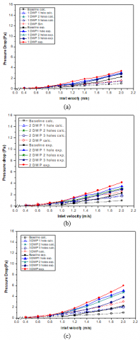
4.7 Effect of vortex generator on pressure loss penalty
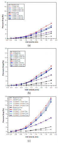
Comparison of pressure drop for cases of delta winglet pair vortex generators (DWP VGs) with variations of one, two, and three holes and without holes is shown in Figure 12. The use of VG is able to enhance heat transfer, but it has an impact on the increase in pressure drop [18, 29]. The results of numerical calculations and experimental results show a similar tendency. The deviation between the simulation and experimental results is observed to be large enough at flow velocities greater than 1.2 m/s. Simulation and experiment results illustrate that pressure drop increases with increasing fluid velocity. This increase in pressure drop is caused by an increase in the drag force formed by increasing flow velocity [18]. Simulation results indicate that the addition of three holes in one pair of DW VGs yields a 9.3% reduction in pressure drop at a flow velocity of 2 m/s, as shown in Figure 12 (a). The highest decrease in pressure drop with three holes in VG is found in the case of two pairs of DW VGs (2 DWP VGs) of 42.5% at a flow velocity of 2 m/s. The results of the current study also show that pressure drop increases with the increase in the number of pairs of VGs, as can be seen in Figure 12. The reason is the flow resistance produced by the friction between the flow and the surface of the VGs and the backflow caused by a longitudinal vortex formed from VGs [30]. By comparing Figures 13 and 12, similar tendencies are shown in the use of CDWP VGs. Pressure drop increases with the flow velocity. Pressure drop is reduced by 25.6% by providing three holes for the installation of one pair of CDW VGs at a flow velocity of 2 m/s. While for the case of 3 pairs of CDW VGs, the pressure drop is decreased by 11.6% by giving three holes in the VGs at a flow velocity of 2 m/s. By comparing the results of the investigations shown in Figures 12 and 13, it is concluded that the use of concave VG, resulting in a higher pressure drop compared to the use of flat form VG. This is caused by the stronger backflow generated by the CDWP VGs because of the stronger longitudinal vortex.
Figure 12. Pressure drop for DW VGs with different number of pair and hole in variations of inlet velocities
Figure 13. Pressure drop for CDW VGs with different number of pair and hole in variations of inlet velocities
Numerical analysis of the effects of using perforated DWP and CDWP VGs on heat transfer and flow resistance has been carried out. Its effect on heat transfer and pressure drop can be summarized as follows:
(1) The longitudinal vortex radius generated by CDWP VGs was greater than that generated by DWP VGs. The common-flow up (CFU) configuration produces counter-rotating flow observed in the wake area.
(2) Based on the analysis of the longitudinal vortex intensity, the longitudinal vortex intensity produced by CDWP VGs was higher than that generated by DWP VGs at the same location. The longitudinal vortex intensity decreased slightly with the increase in the number of holes in the VGs.
(3) Heat transfer from the flow near the wall to the middle of the flow for the use of DWP VGs was slower than the installation of VGs CDWP. Holes in VGs caused interference with the longitudinal vortex formed.
(4) The use of CDWP VGs increased the heat transfer rate higher than the use of DWP VGs. The use of holes in VGs had little impact on the decrease in convection heat transfer coefficient.
(5) The synergy angle in the use of CDWP VGs was found to be smaller than the use of DWP VGs. From the concept of the synergy principle, the smallest synergy angle was observed for cases of VGs without holes in either DWP or CDWP.
(6) The use of CDWP VGs yielded a higher pressure drop compared to the use of DWP VGs. Holes in VGs can reduce pressure drop significantly.
This work was supported by the International Research Publication of Diponegoro University, Indonesia (RPI), with contract number: 329-106/UN7.P4.3/PP/2019. The authors are grateful to all research members, especially Lab. Thermofluid of Mechanical Engineering of Diponegoro University Indonesia, Lab. Energy Conversion Machine of Mechanical Engineering of Malang State University (UM) Indonesia.
|
A |
Surface area (m2) |
|
Cp |
Specific heat (J/kg.K) |
|
Dh |
Hydraulic diameter (m) |
|
f |
Friction factor |
|
Gk |
Generation of k (kg/m4.s4) |
|
$G_{\omega}$ |
Generation of $\omega$ (kg/m4.s4) |
|
h |
Convection coefficient (W/m2K) |
|
I |
Turbulence intensity (%) |
|
j |
Colburn factor |
|
k |
Turbulence kinetic energy (J/kg) |
|
L |
Length (m) |
|
$\dot{m}$ |
Mass flow rate (kg/s) |
|
Nu |
Nusselt number |
|
p |
pressure (Pa) |
|
Pr |
Prandtl number |
|
Q |
Convection heat transfer rate (J/s) |
|
Re |
Reynolds number |
|
St |
Stanton number |
|
T |
Temperature (K) |
|
u, v, w |
x, y, z velocity components (m/s) |
|
ui |
velocity in i-direction (m/s) |
|
uk |
velocity in k-direction (m/s) |
|
x, y, z |
Cartesian coordinates |
|
Yk |
Dissipation of k due to turbulence (kg2/m4.s4) |
|
$Y_{\omega}$ |
Dissipation of $\omega$ due to turbulence (kg2/m4.s4) |
|
Greek letter |
|
|
$\rho$ |
Density (kg/m3) |
|
$\Gamma$ |
Diffusion Coefficient (kg/m.s) |
|
$\Gamma_{k}$ |
Effective of Diffusivities k (kg/m.s) |
|
$\Gamma_{\omega}$ |
Effective of Diffusivities $\omega$ (kg/m.s) |
|
$\sigma_{k}$ |
Prandtl number of k |
|
$\sigma_{\omega}$ |
Prandtl number of $\omega$ |
|
$\Delta P$ |
Pressure drop (Pa) |
|
$\omega$ |
Specific dissipation rate (1/s) |
|
$\theta$ |
Synergy angle (°) |
|
$\mu$ |
Viscosity (kg/m.s) |
|
Ω |
Vortex Intensity |
|
$\omega_{x}$ |
Vorticity (1/s) |
|
$\mu_{t}$ |
Turbulent Viscosity (kg/m.s) |
|
$\lambda$ |
Thermal conductivity (W/m.K) |
|
Subscript |
|
|
in |
inlet |
|
w |
wall |
|
out |
outlet |
[1] Wu, J., Tao, W. (2008). Numerical study on laminar convection heat transfer in a rectangular channel with longitudinal vortex generator. Part A: Verification of field synergy principle. International Journal of Heat and Mass Transfer, 51(5-6): 1179-1191. https://doi.org/10.1016/j.ijheatmasstransfer.2007.03.032
[2] Fiebig, M. (1998). Vortices, generators and heat transfer. Chemical Engineering Research and Design, 76(2): 108-123. https://doi.org/10.1205/026387698524686
[3] Gholami, A., Wahid, M.A., Mohammed, H. (2014). Heat transfer enhancement and pressure drop for fin-and-tube compact heat exchangers with wavy rectangular winglet-type vortex generators. International Communications in Heat and Mass Transfer, 54: 132-140. https://doi.org/10.1016/j.icheatmasstransfer.2014.02.016
[4] Du, X., Feng, L., Li, L., Yang, L., Yang, Y. (2014). Heat transfer enhancement of wavy finned flat tube by punched longitudinal vortex generators. International Journal of Heat and Mass Transfer, 75: 368-380. https://doi.org/10.1016/j.ijheatmasstransfer.2014.03.081
[5] Garg, A.K., Dhingra, S. (2014). Numerical simulation for heat transfer enhancement in a triangular ribbed channel with winglet vortex generators. International Journal of Engineering Research and General Science, 2(4): 549-561.
[6] Li, L., Du, X., Zhang, Y., Yang, L., Yang, Y. (2015). Numerical simulation on flow and heat transfer of fin-and-tube heat exchanger with longitudinal vortex generators. International Journal of Thermal Sciences, 92: 85-96. https://doi.org/10.1016/j.ijthermalsci.2015.01.030
[7] Ebrahimi, A., Roohi, E., Kheradmand, S. (2015). Numerical study of liquid flow and heat transfer in rectangular microchannel with longitudinal vortex generators. Applied Thermal Engineering, 78: 576-583. https://doi.org/10.1016/j.applthermaleng.2014.12.006
[8] Lin, Z., Wang, L., Lin, M., Dang, W., Zhang, Y. (2017). Numerical study of the laminar flow and heat transfer characteristics in a tube inserting a twisted tape having parallelogram winglet vortex generators. Applied Thermal Engineering, 115: 644-658. https://doi.org/10.1016/j.applthermaleng.2016.12.142
[9] Lu, G., Zhou, G. (2016). Numerical simulation on performances of plane and curved winglet – Pair vortex generators in a rectangular channel and field synergy analysis. International Journal of Thermal Sciences, 109: 323-333. https://doi.org/10.1016/j.ijthermalsci.2016.06.024
[10] Oneissi, M., Habchi, C., Russeil, S., Bougeard, D., Lemenand, T. (2016). Novel design of delta winglet pair vortex generator for heat transfer enhancement. International Journal of Thermal Sciences, 109: 1-9. https://doi.org/10.1016/j.ijthermalsci.2016.05.025
[11] Dezan, D.J., Salviano, L.O., Yanagihara, J.I. (2016). Heat transfer enhancement and optimization of flat-tube multilouvered fin compact heat exchangers with delta-winglet vortex generators. Applied Thermal Engineering, 101: 576-591. https://doi.org/10.1016/j.applthermaleng.2015.12.107
[12] Saha, P., Biswas, G., Sarkar, S. (2014). Comparison of winglet-type vortex generators periodically deployed in a plate-fin heat exchanger – A synergy based analysis. International Journal of Heat and Mass Transfer, 74: 292-305. https://doi.org/10.1016/j.ijheatmasstransfer.2014.03.015
[13] Xu, Y., Islam, M., Kharoua, N. (2018). Experimental study of thermal performance and flow behaviour with winglet vortex generators in a circular tube. Applied Thermal Engineering, 135: 257-268. https://doi.org/10.1016/j.applthermaleng.2018.01.112
[14] Song, K., Xi, Z., Su, M., Wang, L., Wu, X., Wang, L. (2017). Effect of geometric size of curved delta winglet vortex generators and tube pitch on heat transfer characteristics of fin-tube heat exchanger. Experimental Thermal and Fluid Science, 82: 8-18. https://doi.org/10.1016/j.expthermflusci.2016.11.002
[15] Syaiful, Jalil, R., Hambali, I., Bae, M.W. (2015). Numerical simulation of concave delta winglet vortex generator effect on heat transfer augmentation in airflow inside a channel. Proceedings of the Seventh International Symposium on Mechanics, Aerospace and Informatics Engineering 2015, Jinju, Korea. https://doi.org/10.1063/1.4968278
[16] Syaiful, Reviansyah, G., Bae, M.W. (2016). Attack angle effect of concave delta winglet vortex generator on heat transfer augmentation in fin-and_tube heat exchanger for EGR cooler application by numerical simulation. FISITA 2016 World Automotive Congress, Korea.
[17] Syaiful, Sugirl, G., Soetanto, M.F., Bae, M. (2017). Effect of concave rectangular winglet vortex generator on convection coefficient of heat transfer. AIP Conference Proceedings, 1788: 030025. https://doi.org/10.1063/1.4968278
[18] Syaiful, S., Ayutasari, A., Soetanto, M.F., Siswantara, A.I., Bae, M. (2017). Thermo-hydrodynamics performance analysis of fluid flow through concave delta winglet vortex generators by numerical simulation. International Journal of Technology, 8(7): 1276-1285. https://doi.org/10.14716/ijtech.v8i7.706
[19] Syaiful, Yunianto, B., Saryanto, A., Bae, M. (2018). Pressure loss penalty improvement of airflow through heated plate mounted by delta winglet vortex generator: An experimental study. AIP Conference Proceedings, 1984: 020033. https://doi.org/10.1063/1.5046617
[20] Wilcox, D.C. (1993). Turbulence Modeling for CFD. DCW Industries, Inc., California.
[21] Torii, K., Kwak, K., Nishino, K. (2002). Heat transfer enhancement accompanying pressure-loss reduction with winglet-type vortex generators for fin-tube heat exchangers. International Journal of Heat and Mass Transfer, 45(18): 3795-3801. https://doi.org/10.1016/s0017-9310(02)00080-7
[22] Malatesta, V., Souza, L.F., Liu, J.T., Kloker, M.J. (2015). Heat transfer analysis in a flow over concave wall with primary and secondary instabilities. Procedia IUTAM, 14: 487-495. https://doi.org/10.1016/j.piutam.2015.03.077
[23] Biswas, G., Torii, K., Fujii, D., Nishino, K. (1996). Numerical and experimental determination of flow structure and heat transfer effects of longitudinal vortices in a channel flow. International Journal of Heat and Mass Transfer, 39(16): 3441-3451. https://doi.org/10.1016/0017-9310(95)00398-3
[24] Zhou, G., Feng, Z. (2014). Experimental investigations of heat transfer enhancement by plane and curved winglet type vortex generators with punched holes. International Journal of Thermal Sciences, 78: 26-35. https://doi.org/10.1016/j.ijthermalsci.2013.11.010
[25] Deb, P., Biswas, G., Mitra, N. (1995). Heat transfer and flow structure in laminar and turbulent flows in a rectangular channel with longitudinal vortices. International Journal of Heat and Mass Transfer, 38(13): 2427-2444. https://doi.org/10.1016/0017-9310(94)00357-2
[26] Khoshvaght-Aliabadi, M., Baneshi, Z., Khaligh, S. (2017). Analysis on performance of nanofluid-cooled vortex-generator channels with variable longitudinal spacing among delta-winglets. Applied Thermal Engineering, 122: 1-10. https://doi.org/10.1016/j.applthermaleng.2017.05.016
[27] Guo, Z.Y., Li, D.Y., Wang, B.X. (1998). A novel concept for convective heat transfer enhancement. International Journal of Heat and Mass Transfer, 41: 2221-2225. https://doi.org/10.1016/S0017-9310(97)00272-X
[28] Liu, J., Chen, S., Gan, M., Chen, Q. (2018). Heat transfer and flow resistance characteristics inside an innovative vortex enhanced tube. Applied Thermal Engineering, 144: 702-710. https://doi.org/10.1016/j.applthermaleng.2018.04.082
[29] Naik, H., Harikrishnan, S., Tiwari, S. (2018). Numerical investigations on heat transfer characteristics of curved rectangular winglet placed in a channel. International Journal of Thermal Sciences, 129: 489-503. https://doi.org/10.1016/j.ijthermalsci.2018.03.028
[30] Han, Z., Xu, Z., Wang, J. (2018). Numerical simulation on heat transfer characteristics of rectangular vortex generators with a hole. International Journal of Heat and Mass Transfer, 126: 993-1001. https://doi.org/10.1016/j.ijheatmasstransfer.2018.06.081