Lin Gao
© 2019 IIETA. This article is published by IIETA and is licensed under the CC BY 4.0 license (http://creativecommons.org/licenses/by/4.0/).
OPEN ACCESS
Dry gas seal (DGS) is a novel sealing method with broad prospects in various shaft sealing applications. it is vital for the design of dry gas seals to achieve flow field information by numerical method, including the influences of the Parameters of DGS on sealing performance. Based on FLUENT, this paper explores the three-dimensional (3D) flow fields of the DGS of spiral groove and T-groove at different rotation speeds, outer radius pressures and gas film thicknesses, and obtains the numerical features (e.g. pressure distribution) of the DGS under different working conditions. The results show that the rotation speed of the DGS has a promoting effect on the hydrodynamic effect, while the outer radius pressure and gas film thickness both suppress the hydrodynamic effect. The research findings provide an important reference for the design and manufacturing of fluid machines like pumps and stirring reactors.
dry gas seal (DGS), pressure distribution, spiral groove, T-groove
Dry gas seal (DGS) is a mechanical seal lubricated with a gas film that is a few micrometres in thickness. Capable of “sealing up gas with gas”, the DGS has been widely adopted for high-speed fluid machines like centrifugal compressors. Recently, a growing attention has been paid to apply the DGS to low-speed equipment, such as pumps and reactors [1, 2]. The DGS is less costly to fabricate and maintain, more energy-efficient and more durable than the other seals commonly used in fluid machines, namely, labyrinth seal, mechanical seal that seals up gas with oil, and the combination of mechanical seal and floating-ring seal [3].
The numerical theory on the DGS has long been a research hotspot. The most representative studies are as follows. Reddi and Chu [4] were the first to explore the steady-state performance of low-speed spiral groove gas bearing, using incremental Galerkin method. Zirkelback and Andrest [5] employed the incremental Galerkin method to compute the dynamic force coefficient of the gas lubricated seal (GLS) of spiral groove at low and medium speeds. Vladimir et al. [6] analysed the flow fields of the GLS faces of spiral groove on commercial software, revealing the strong inertia effect in the flow field of each seal face. Wang et al. [7] investigated the pressure distribution on each seal face. Xiao et al. [8] also used FLUENT, a flow field analysis software, to numerically simulate the three-dimensional (3D) flow field.
The advancement of science and technology has put forward increasing strict requirements on the design of pumps and other centrifugal machines. This calls for more accurate numerical simulation of the flow field and parameter variation of the DGS. Against this backdrop, numerous scholars have been improving the accuracy of relevant numerical methods and trying to capture the exact variation laws of sealing parameters, with the aim to facilitate the engineering design of the DGS.
Considering the dynamic effect of seal faces, this paper probes into the numerical simulation of the DGS with T-groove and spiral groove. The groove type of each seal face is critical to the design of the DGS. To date, various groove types have been developed at home and abroad. The existing grooves generally fall into two categories: single-directional groove and bi-directional groove. Only the former is related to the direction f rotation. The spiral groove is a typical single-directional groove [9, 10], while the T-groove is a representative bi-directional groove. In this paper, the 3D flow fields of the DGS faces are simulated for both spiral groove and T-groove at different rotation speeds and different inlet pressures. Through the simulation, the author obtained the numerical features (e.g. pressure distribution) of the DGS faces under different working conditions, and, on this basis, determined the influence mechanism of parameter variation on the sealing performance. Influences on sealing performance by groove type, thickness, speed and inlet pressure were complex, and also it was a complex process influenced by many other factors. Therefore, it is necessary to analyze it by means of simulated calculation.
The remainder of this paper is organized as follows: Section 2 (theoretical model) simulates the relative motion between the rotary ring and the stationary ring by the reference frame method based on the Navier–Stokes (N-S) equation; Section 3 (results of numerical simulation) presents and analyses the numerical results of different groove types under different parameters; Section 4 (conclusions) sums up the calculation results from the angle of hydrodynamic effect.
Considering the structure of the seal rings and the sealing system, a few hypotheses were made on the steady-state flow field of the gas film between the seal faces, in the light of the basic theory on fluid mechanics [11]. On this basis, the dimensionless N-S governing equation for completely compressible gas in cylindrical coordinates can be established as:
$\frac{\partial }{R\partial R}\left( P{{H}^{3}}R\frac{\partial P}{\partial R} \right)+\frac{\partial }{R\partial R}\left( P{{H}^{3}}\frac{\partial P}{R\partial \theta } \right)=\frac{6\mu \omega \left( \frac{{{r}_{0}}}{{{h}_{0}}} \right)}{{{p}_{0}}}\frac{\partial \left( PH \right)}{\partial \theta }$ (1)
where, R=r/ri (ri: the inner radius of each seal face); P=p/pi (pi is the pressure on the inner radius side); H=h/h0 (h0 is the gas film thickness in the non-grooved area between the seal faces); μ is dynamic viscosity; ω is the rotational angular velocity.
Based on structured grids, FLUENT is a universal solver of computational Fluid Dynamics (CFD) and the popular commercial package in the world. When applied to the simulation of unstructured grids, the software solves the fluid mechanics of incompressible fluid and medium-pressure compressible fluid with the finite volume method. In this research, all numerical simulations are carried out on FLUENT. In addition, the semi-implicit method for pressure-linked equations (SIMPLE) was adopted to enhance computing accuracy.
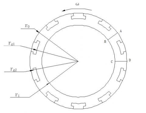
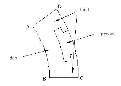
In this paper, the gas film between the seal faces is selected to examine the gas film pressure field. The calculation area only covers 1/Ng (Ng is the number of grooves) of each seal face, due to the symmetry and periodic distribution of the grooves on the seal face. For convenience, our model was constructed for only one groove, one land and one dam, as Figure 1.
Figure 1. Sketch of T-groove
The GLS gas film lies between the rotary and stationary rings, which move relative to each other. FLUTENT provides three models to simulate the rotary motion: reference frame method, sliding mesh method and mixing plane method. Focusing on the fluid flow relative to the hydrodynamic groove, this paper selects the reference frame method to simulate the relative motion between the rotary and stationary rings.
The fluid area was taken as the reference frame and the pressure was given. The surface of the stationary ring was set as a zero-pressure wall in the reference frame, while that of the rotary ring was set as a stationary wall in the absolute frame. These settings ensure that the fluid rotates between the seal faces. The relative pressure between the stationary ring and the fluid was set to zero, because there is not relative motion between the two objects. The rotary ring was considered static in the absolute frame, reflecting its motion relative to the fluid at a certain speed. In this way, the relative motion between the two rings can be simulated accurately.
3.1 T-groove
The bi-directional rotary DGS has a good sealing performance. This type of DGS enjoys good hydrodynamic effect while realizing two-way rotations. Therefore, more and more attention has been paid to the DGS that enables two-way rotations [12]. The T-groove DGS has attracted considerable interests for its two-way rotation ability.
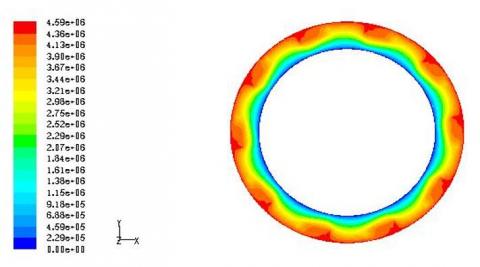
The values of discrete points were solved by the CFD method. On this basis, the gas film pressure distribution (Figure 2) was obtained by the post-processing tool of FLUENT. As shown in Figure 2, the pressure was much smaller and clearly more uniform in the land and dam areas than in the groove area. In addition, a high-pressure region was formed, due to the rotation speed, on the wall surface of the groove area.
Figure 2. Gas film pressure distribution of T-groove
Figure 2 shows a steep yet non-uniform pressure gradient on the gas film between the seal faces. Overall, the pressure gradually declined from the inlet to the outlet. However, the T-groove severely limited the variation of seal face pressure in the groove area. This means the presence of the T-groove produces a certain hydrodynamic effect. But this effect is not enough to increase the pressure at the root of T-groove above the inlet pressure.
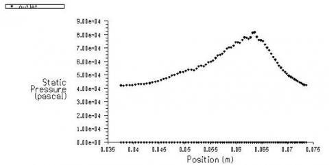
Figure 3. Mean radial distribution of gas film pressure
Figure 3 intuitively describes the mean radial distribution of gas film pressure. As per the figure, the gas film pressure variation can be roughly divided into two parts from the inner radius to the outer radius: (1) The pressure showed an approximately linear growth from the inner radius to the groove root; (2) The pressure gradually declined from the groove root to the outer radius, because the hydrodynamic effect created a higher pressure at the groove root than the pressure at the outer radius.
The DGS performance of T-groove is affected by various factors to different degrees. In general, the influencing factors can be categorized into working parameters and the geometric parameters of the seal faces. The working parameters include the rotation speed and medium pressure of the seal, while the geometric parameters include the groove depth hg, the helix angle Q, the number of grooves Ng, the groove-dam length ratio γ and the groove-land width ratio δ. Table 1 lists the geometric and working parameters of T-groove DGS obtained through our numerical simulation.
Table 1. The geometric and working parameters of T-groove DGS
|
Item |
Parameter |
Item |
Parameter |
|
Outer radius r0 |
77.78 mm |
Groove depth hg |
5 μm |
|
Inner radius ri |
58.42 mm |
Number of grooves Ng |
10 |
|
Groove radius rg1 |
69 mm |
Outer pressure P0 |
4,585,200 Pa |
|
Groove radius rg2 |
73.39 mm |
Inner pressure Pi |
101,325 Pa |
|
Groove-land width ratio δ |
1 |
Medium |
Nitrogen |
(1) Effects of ration speed on sealing performance
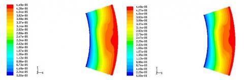
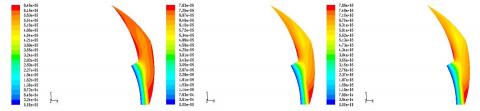
Figure 4 shows the distributions of face pressure at different rotation speeds, when the gas film is 5 μm thick. It can be inferred that the hydrodynamic effect of the T-groove changed significantly with the increase in rotation speed. The faster the rotation, the more obvious the hydrodynamic effect. When the speed reached 20,000 rpm, the pressure at the groove root increased to the level of the inlet pressure. Hence, the groove root pressure will surpass the inlet pressure with further growth in rotation speed. The results show that the hydrodynamic effect of the DGS with T-groove directly hinges on the rotation speed of the seal.
(2) Effects of outer radius pressure on sealing performance
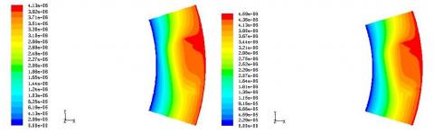
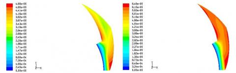
Normally, the pressure at the inner radius of the T-groove is the atmospheric pressure, and the pressure at the outer radius is the buffer gas pressure, which changes with the pressure conditions of the seal. Figure 5 displays the pressure distribution of the seal faces under different outer radius pressures. It can be learned that, with the growth in outer radius pressure, the hydrodynamic effect of the seal weakened, failing to create a high pressure at groove root.
The hydrodynamic effect was more prominent in Figure 5(d) than in Figure 4(d), when the rotation speed remains unchanged at 28,600rpm. This is attributable to the relatively low pressure at the outer radius of Figure 5(d). Therefore, the pressure difference between the inner and outer radii of the seal has a significant impact on the hydrodynamic effect. This effect is more likely to occur at a small pressure difference.
(3) Effects of gas film thickness on sealing performance
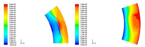
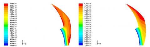
Figure 6 presents the pressure distributions of the seal faces at different gas film thicknesses (2 and 5 μm), while the other parameters remain the same. As shown in Figure 6, the decrease in gas film thickness promoted the hydrodynamic effect and enhanced the gas film pressure. In particular, the gas film pressure surged up at the groove root, forming a high-pressure region, where the pressure is greater than the inlet pressure. On the contrary, the increase of gas film thickness suppressed the hydrodynamic effect and thus the gas film pressure. In this case, no high-pressure region can be formed at the groove root by the gas entering the T-groove.
It can be seen clearly from Figure 6(a) that the pressure at groove root differed greatly from the outer radius pressure, because of the high-pressure region at groove root induced by the hydrodynamic effect. By contrast, the pressure distributed uniformly from the inlet to the outlet in the land area.
(a) ω=6000 rpm (b) ω=10000 rpm
(c) ω=20000 rpm (d) ω=28600 rpm
Figure 4. Cloud map of pressure distributions at different rotation speeds
(a) P=4 MPa (b) P=4.5 MPa
(c) P=6 MPa (d) P=7 MPa
Figure 5. Cloud map of pressure distributions at different outer radius pressures
(a) h0=2 μm (b) h0=5 μm
Figure 6. Cloud map of pressure distributions at different gas film thicknesses
3.2 Spiral groove
The spiral groove is the most popular single-direction groove in industrial applications [13]. This is because the groove can produce a high stiffness gas film with a very small clearance, thanks to its good hydrodynamic effect.
At present, the main types of spiral grooves are logarithmic helix and Archimedean helix. The former is equal groove angle helix, and the latter is variable groove angle helix. The sagittal diameter of logarithmic helix is:
$r = r _ { g } e ^ { \theta \cdot \tan \alpha }$ (2)
In which, rg is the spiral groove radius and α is the helical angle, as the angle between helix and circumferential tangent. Based on the gas film on the sealing face, the periodic distribution of film pressure along the circumference is 2n/N, due to the spiral grooves on the seal face are evenly distributed. Therefore, one groove, one land and its corresponding dam area can be taken as the research object.
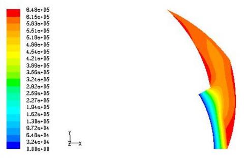
Figure 7 shows a steep yet nonuniform pressure gradient on the gas film between the seal faces. Overall, the pressure gradually decreased from the outer radius to the inner radius. Nevertheless, the spiral groove basically eliminated the variation of seal face pressure in the groove area. Hence, the presence of the spiral groove creates a certain hydrodynamic effect, which is not enough to increase the groove root pressure above the inlet pressure.
Figure 7. Cloud map of pressure distribution of spiral groove
The DGS performance of spiral groove is also influenced by various factors to different degrees. The influencing factors can also be groups into working parameters and the geometric parameters of the seal faces. The former includes the rotation speed and medium pressure of the seal, while latter covers the groove depth hg, the helix angle Q, the number of grooves Ng, the groove-dam length ratio γ and the groove-land width ratio δ. Our simulation aims to disclose how the sealing performance of spiral groove is affected by the rotation speed, outer radius pressure and gas film thickness. The simulated geometric and working parameters of the GLS faces with the spiral groove are presented in Table 2 below.
Table 2. The geometric and working parameters of spiral groove
|
Item |
Parameter |
Item |
Parameter |
|
Outer radius r0 |
90 mm |
Helix angle α |
20∘ |
|
Inner radius ri |
51 mm |
Groove depth hg |
6 μm |
|
Groove radius rg |
77 mm |
Number of grooves Ng |
12 |
|
Balance radius rb |
75 mm |
Outer pressure P0 |
1.6 Mp |
|
Groove-dam length ratio γ |
0.5 |
Inner pressure Pi |
0.1 Mp |
|
Groove-land width ratio δ |
1 |
Medium |
Nitrogen |
(1) Effects of ration speed on sealing performance
Figure 8 illustrates the distributions of face pressure at different rotation speeds. It can be seen that the hydrodynamic effect of the spiral groovehad marked changes with the increase in rotation speed. The faster the rotation, the more prominent the hydrodynamic effect. Figures 8(a)~(b) are the pressure distributions at low rotation speeds. It is clear that the pressure decreased continuously from the high-pressure region to the low-pressure region. There was virtually no hydrodynamic effect in the groove area. As shown in Figures 8(c)~(d), the hydrodynamic effect became prominent in the groove area with the increases of the ration speed, but the pressure at the groove root was still below the high inlet pressure. It can be seen from Figures 8(e)~(f) that the groove root pressure finally surpassed the inlet pressure.
Therefore, the DGS hydrodynamic effect of spiral groove depends heavily on the rotation speed of the seal. With the increase of the rotation speed, the opening force of the seal changes rapidly, almost in a linear form. Meanwhile, more gas is pumped into the system, reducing the leakage amount. The reduction is attributable to the high-pressure region at the groove root, which forms under the growing hydrodynamic effect with the increase of rotation speed.
(2) Effects of outer radius pressure on sealing performance
Figure 9 presents the pressure distributions of the seal faces at different outer radius pressures. It can be seen that, with the increase in outer radius pressure, the opening force and leakage amount both surged up, as the hydrodynamic effect weakened, making it difficult for the groove root pressure to surpass the inlet pressure. As shown in Figure 9(a), the hydrodynamic effect of the groove root pressure, originally higher than the inlet pressure, become increasingly unobvious. When the outer radius pressure reached 1.2 MPa, the pressure distribution in the groove area was almost the same with that in the land area. The results reflect the major impact of inner and outer radii on the hydrodynamic effect of spiral groove, revealing that a small difference between inner and outer radii is conducive to the generation of hydrodynamic effect.
(3) Effects of gas film thickness on sealing performance
The above analysis assumes that the gas film is 2 μm thick. In fact, the gas film only exists stably under the equilibrium of the opening and closing force. Any disturbance to the seal will cause a slight variation in the clearance, changing the thickness of the gas film. The thickness changes in turn increases or decreases the opening force. When the opening force achieves a new equilibrium with the closing force, a new stable gas film will form again. Therefore, there is a dynamic equilibrium between the opening force and the thickness of the gas film.
Figure 10 shows the pressure distributions at two gas film thicknesses, without changing the other parameters. It can be seen that the decrease in gas film thickness promoted the hydrodynamic effect and increased the gas film pressure. The pressure increase was particularly obvious at the groove root. The pressure in the resulting high-pressure region surpassed the inlet pressure. On the contrary, the increase of gas film thickness suppressed the hydrodynamic effect and thus the gas film pressure. Thus, no high-pressure region can be formed at the groove root by the gas entering the spiral groove.
(a) ω=3000 rpm (b) ω=5000 rpm (c) ω=8000 rpm
(d) ω=10000 rpm (e) ω=12000 rpm (f) ω=15000 rpm
Figure 8. Cloud map of pressure distributions at different rotation speeds
(a) P=0.3 Mpa (b) P=0.6 Mpa
(c) P=1.0 Mpa (d) P=1.2 Mpa( e) P=1.5 Mpa
Figure 9. Cloud map of pressure distributions at different outer radius pressures
(a) h0=2 μm (b) h0=4 μm
Figure 10. Cloud map of pressure distributions at different gas film thicknesses
This paper sets up 3D models for the DGS seal faces of spiral groove and T-groove, and obtains their pressure distributions using the ideal gas model and laminar flow model in FLUENT. The main conclusions are as follows:
(1) The gas film pressures of spiral groove and T-groove were analysed at different rotation speeds. The results show that the hydrodynamic effect was unobvious at low speeds; with the increase in rotation speed, the groove root exhibited a prominent hydrodynamic effect, in that the local pressure, originally below the outer radius pressure, surpassed the high pressure at the outer radius.
(2) The gas film pressures of spiral groove and T-groove were also analysed at different outer radius pressures. It is concluded that the hydrodynamic effect was prominent when the outer radius pressure was low. In this case, a high-pressure region was formed at the groove root, where the pressure is greater than the outer radius pressure. The growth in outer radius pressure weakened the hydrodynamic effect, reducing the groove root pressure below the outer radius pressure.
(3) The gas film pressures were examined at different film thicknesses, revealing that the hydrodynamic pressure is negatively correlated with film thickness.
[1] Jin, X.Q., Song, P.Y. (2007). Developments of dry gas sealing technology for pumps. Machinery, 34(7): 6-8.
[2] Song, Y.H. (2008). Technical research on the T-groove dry gas seals of the compressor. Xihua University.
[3] Chen, Y., Peng, X., Jiang, J., Meng, X.K., Li, J.Y. (2018). Experimental and theoretical studies of the dynamic behavior of a spiral-groove dry gas seal at high-speeds. Tribology International, 125: 17-26. https://doi.org/10.1016/j.triboint.2018.04.005
[4] Reddi, M.M., Chu, T.Y. (1970). Finite element solution of the steady-state compressible lubrication problem. Journal of Lubrication Technology, 92(3): 502-503. http://dx.doi.org/10.1115/1.3451456
[5] Zirkelback, N.L., Andres, L.S. (1999). Effect of frequency excitation on force coefficient of spiral groove gas seals. Journal of Tribology, 121(4): 853-863. http://dx.doi.org/10.1115/1.2834145
[6] Vladimir, K.M., Jack, B., Robert, C.H. (2001). Computational studies of flow and pressure distributions in a spiral groove seals. 9th Annual Conferenceof CFD SocietyofCanada, Kitchener, Ontario.
[7] Wang, H.S., Cheng, Huang, Z.P., Wang, X.L. (2004). Numerical simulation of the face flow field on radial groove dry gas seal. Chinese Hydraulics& Pneumatics, 10: 21-23. http://dx.chinadoi.cn/10.3969/j.issn.1000-4858.2004.10.009
[8] Xiao, N.N., Kun, Y.Z., Qiu, X.Z., Cai, J.N. (2005). Simulation of spiral groove dry gas seals by use of CFD. Process Equipment & Piping, (42)4: 56-58. http://dx.chinadoi.cn/10.3969/j.issn.1009-3281.2005.04.014
[9] Gent, A.N. (1992). Engineering with rubber: How to design rubber components. USA: Hanser Gardner Publications. https://doi.org/10.3139/9783446428713.fm
[10] Bai, S., Peng, X., Li, Y., Sheng, S. (2010). A hydrodynamic laser surface-textured gas mechanical face seal. Tribology Letters, 38(2): 187-194. https://doi.org/10.1007/s11249-010-9589-1
[11] Gerber, A.D., Gerber, E.A. (2019). Oscillation frequency of flat ring of viscous capillary fluid. International Journal of Heat and Technology, 37(1): 77-79. https://doi.org/10.18280/ijht.370109
[12] Chen, W., Song, P.Y., Mao, W.Y., Jiao, F. (2015). Numerical analysis of temperature field of gas film in spiral groove dry gas seal. Journal of Drainage and Irrigation Machinery Engineering, 33(5): 422-428. http://dx.doi.org/10.3969/j.issn.1674-8530.15.0013
[13] Jiang, X.W. (20014). Numerical simulation and optimum groove geometric parameters for spiral groove dry gas seal. Nanjing University of Technology.