Ece Ayli
© 2019 IIETA. This article is published by IIETA and is licensed under the CC BY 4.0 license (http://creativecommons.org/licenses/by/4.0/).
OPEN ACCESS
Hydroenergy is one of the richest and most useful renewable energy sources in the world. Hydropower is a vital source as it is the clean energy source, sustainable and last but not least it is also cost-effective. One of the most important parameters that affect the performance of the hydraulic machines is the cavitation phenomenon, which is defined as the formation of the vapor bubbles in the liquid through any hydraulic turbine. In this paper, hydraulic machines, cavitation, types of cavitation are briefly described. After theoretical studies, analytical and numerical researches about cavitation in hydraulic machinery are discussed extensively. With those studies which are summarized in this paper covers a lot of ground about cavitation on the other hand further studies are needed about cavitation in hydro turbines. Numerical methods provide sufficient predictions for cavitation. However, numerical results should be verified by experimental measurements and detection methods to decide what intensity and which shape of cavitation is hazardous and vital, where the local pressure is lower than the vapor pressure and at which static pressure cavities start to grow and collapse.
cavitation, Francis turbine, Pelton turbine, Kaplan turbine, hydropower
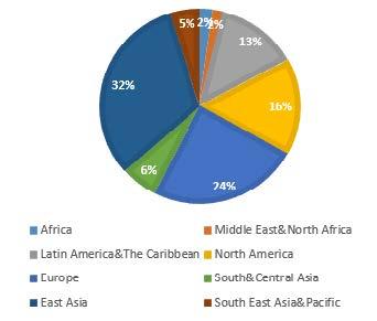
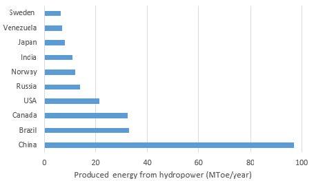
In the last decades, using the energy that comes from natural resources becomes a popular way to produce energy. The leading sources of clean energy resources are solar, wind and hydroenergy. According to the World Energy Council, hydropower is the leading renewable energy source for electricity generation globally supplying 71 % of all renewable electricity [1]. In Figure 1 and 2, hydropower ınstalled capacity by region and top hydropower producing countries are given where MToe refers to Million tonnes of Oil Equivalent. Due to the 2016 data, the leading hydropower generating countries are China, Brazil, and Canada.
Figure 1. Hydropower installed capacity by region [1]
It is a vital energy source with its outstanding properties like one of the richest and most useful energy sources, which is sustainable and clean. In the hydraulic systems according to use the energy of the flowing water, the headwater is taken from the high ground, and it flows to the turbine to convert the potential energy to the kinetic energy. When water hits the turbine blades, it turns the turbine, and kinetic energy of the water is converted to the mechanical energy. The mechanical energy is converted to electricity when the turbine turns the generator rotor. The most important parameter to generate energy with the help of the water forces is the hydraulic head and pressure difference. The power generated from the turbine is relevant to the water head and flow rate [2].
Figure 2. Top hydropower producing countries [1]
1.1 Hydraulic turbines
For many centuries, water wheels have been used to generate power even Roman Empire has used the water turbines without knowing that this technology will be used even in the 21st century and still need to be developed. In 1737, Belidor built a waterwheel with curved blades. In 1738 and 1754, two fundamental books are published about the theory of the waterwheels by Daniel Bernoulli and Leonard Euler respectively. In 1804, the ancestor of the modern turbine was developed by Benjamin Tyler, which is known as Wry-Fly [3]. In 1827, unlike the Tylers design, Benoit Fourneyron described a new turbine with a horizontal wheel. With starting 4.5 kW power generation, Fourneyron improved his design up to the 45 kW of power generating turbine, which can reach to the 2300 rpm rotational speed and 80 % efficiency. After 68 years from his preliminary design, Fourneyron turbines were installed to the Niagara Falls. In 1844, Uriah A Boyden improved the Foruneyrons turbine performance with changing the shape of the blades which becomes similar to Francis Turbine. After five years from the Boydens modification, James B. Francis improved the inward flow reaction turbine, which reaches to the 90 % efficiency values, which is the first modern water turbine and called as Francis Turbine. Also, he developed a methodology for the turbine design procedure. In the next phase, turbine companies put Francis type turbines to large-scale production. In 1879, Lester Pelton developed the Pelton wheel. At the beginning of the 20th century, Viktor Kaplan created the Kaplan turbine, a propeller-type machine [3-5]. The detailed historical development of Hydraulic Turbines is described in the book of Layton extensively [4].
Up to today, scientists come a long way from the first turbine design to today’s high-performance turbines, which are flexible, low cost and emission-friendly. In the last decades, in the designing, optimization, and performance improving procedure of turbines, numerical studies with Computational Fluid Dynamics (CFD) tools and model tests are performed. By the advancement in computer technology and the model test procedure, every new day brings some improvement in the designing procedure, performance enhancement techniques, the increment of the chance to use the turbines, increasing the power plant life and aiming to protect the aquatic life. In 2002, a new turbine was introduced, which is called the Vortex Turbine [6]. Another development in HEPPs is using turbines inside of the large diameter water transmission pipes. In inline turbines, a straight pipe, used instead of a spiral case, can distribute water uniformly along the perimeter of the runner. Tanaka Hydropower Co. Ltd. [7] applied inline pipe Francis turbine concept to smaller hydroelectric power plants.
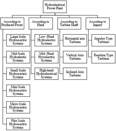
Figure 3. Hydroelectric system classification according to turbine types
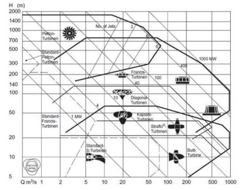
Hydroelectric power plants can be classified in several ways which are given in Figure 3. According to the impact types, two main types of hydraulic turbines are reaction and impulse type turbines. Impulse type turbines work based on the momentum principle. Flow enters the runner and exits in the atmospheric pressure. Examples of the impulse turbines are Pelton type, Turgo type, and Michell-Ossberger type turbines. In the reaction type turbines, flow in the turbine is fully pressurized. Unlike the impulse type turbines, energy is transferred to the runner by action, not by a local impact. The potential energy of water is converted to kinetic energy by a speed rise [8-9]. Examples of the reaction turbines are Francis, Propeller and Kaplan turbine. Figure 4 emphasize which type of turbine is used in what range of the head and flow rate. Also, it gives the power output of the turbine in the given head and flow rate [10].
The classification of the hydro turbines is an important topic as a failure mechanism that the turbine experience varies with the turbine type. Padhy and Saini [11], classifies the failure modes in four main groups; cavitation, erosion, fatigue and material defect which affects reaction and impulse turbines differently.
For instance, cavitation is a crucial problem in the reaction turbines, on the other hand; impulse turbines are most probable to fail due to the erosion [8].
Figure 4. Turbine application chart [12]
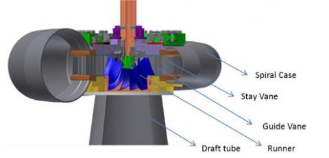
Francis Turbines: Francis type turbines are on the class of the reaction type turbines. Francis turbines are applicable to a wide range of head and specific speed values. Their wide range of applicability and easier structural design makes Francis turbines more advantageous than other hydraulic turbines. The main components of the Francis type turbines are the spiral case, stay vanes, guide vanes, runner and draft tube (Figure 5). Spiral case distributes the flow radially at the inlet to the stay vanes. Stay vanes function is ensuring the structural strength also it directs the flow to the guide vane with an optimal angle. The only movable part of the turbine is the runner, which directs the fluid on to the runner blades at the appropriate angle by rotating about their axis. They are the only devices available to control the flow and thus the power output of a Francis turbine. After guide vane, flow hits the runner blades, and with the effect of this impulse, the turbine generator shaft starts to rotate which enables the production of electricity. Water leaves the runner at minimum pressure, once it releases its energy. The draft tube provides a connection between the runner exit and the tailwater level [13-14].
Figure 5. A typical Francis turbine and generator [15]
Pelton Turbines: Pelton turbine is an impulse type turbine, which extracts energy from the water by converting the available head to the kinetic energy. When a high-speed water jet discharged from the nozzle, it hits to the Pelton wheel, and impulsive force occurs which rotates the turbine. The rotating shaft runs a generator and produces electricity. As it is seen in Figure 4, Pelton turbines are used with a large water head and a small discharge. Numbers of the nozzles are an important parameter in the Pelton turbine design. When the number of nozzles increased also turbine power increases, Pelton turbines can be designed both vertical and horizontal [8, 11]. There are several numerical and experimental investigations about the design of Pelton turbine injector, the influence of jet velocity to the efficiency, bucket design is performed [12].
Axial turbines: The axial turbines are used in low head applications. It is applicable range overlays where Francis turbines cannot use. Unlike the Francis runner blades, Kaplan turbine runners are movable. The water enters the turbine through the guide vanes which forces radial flow to the axial direction. The axial flow hits to the blades and giving its hydraulic energy with producing torque and rotation in the shaft. Semi-Kaplan concept has adjustable stator blades but fixed runner blades. Kaplan turbines have three basic configurations: the vertical axis, the horizontal axis, and bulb turbines. Vertical-axis Kaplan turbines have the advantage of requiring the smallest footprint. Kaplan turbines are used in a head range of 2-40 m and a flow rate range of 3 to 100 m3/s [16-17].
1.2 Cavitation
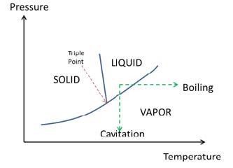
Cavitation is a physical phenomenon which defines bubbles in a fluid flow. According to the Bernoulli principle, when the velocity of the fluid increases, pressure reduces which means a lower boiling point. In other words, reduction of the pressure decreases the boiling point of the fluid till to the ambient temperature. In this situation, cold boiling occurs which contains vapor or gas and vapor-filled bubbles. This case is known as cavitation [18].
According to Knapp et al. [19]'s definition when a body is heated under constant pressure known as boiling, which is given in Figure 6, or when it is pressure is decreased under constant temperature known as cavitation, a new state occurs which contains vapor or gas and vapor-filled bubbles.
A cavitation phenomenon is seen in many branches of engineering. It can be set in in the machines and the systems, which contain sudden pressure and velocity changes. For example, cavitation can be seen in pumps, turbines, propellers, bearings even in the human body [18].
Figure 6. Phase diagram for a simple substance [20]
The common characteristics of the cavitation phenomena are given below [18-19]
Cavitation is the formation of the vapor bubbles in the liquid through any hydraulic turbine. In hydro turbines, dynamic pressure changes can occur. When the local pressure reduced to the vapor pressure cavities occurs and grows. Such a cavity consists of two phases, formation and growth. When the pressure has increased this growing is reversed, and the bubble will collapse suddenly [19, 21-22]. The cavitating flow has the following effects on the hydraulic machines:
2.1 Cavitation in Francis turbines
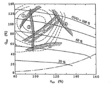
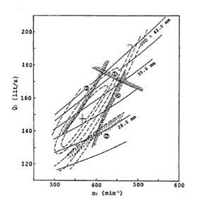
This title is briefly described in Li [24]. In Figure 7, the discharge factor versus the speed factor graph is given. In this graph, possible cavitation regions are given due to the operating ranges. Discharge factor ($Q_{ED}$) and speed factor ($n_{ED}$) are given below.
$n_{ED}=nD/√E,Q_{ED}=Q/(D^2 √E)$ (1)
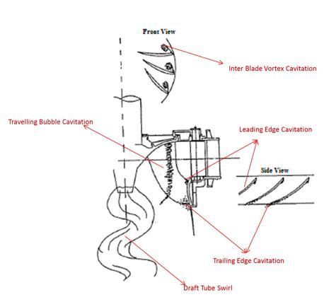
According to Li [24], the main types of the cavitation which can occur in the Francis type turbines are Leading Edge, Travelling Bubble, Draft Tube Swirl, Inter-blade vortex and trailing edge cavitation [24-25].
Figure 7.(a) Cavitation curves due to the discharge and speed factor [18]
Figure 7. (b) Cavitation formation regions [18]
Figure 8. (a) Air Admission to the draft tube [18]
Figure 8.(b) Fin Installation to the draft tube wall [18]
Figure 9. Cavitation in Francis Turbines (a)leading edge cavitation [20] (b) traveling edge cavitation (c) draft tube swirl cavitation (d) Interblade vortex cavitation [FULL REFERENCE © EDP Sciences, 1995., 23]
2.1.1 Cavitation in Pelton turbines
Beside the cavitation erosion, because of the special design of the buckets Pelton type turbines also affected by mechanical erosions. Due to the high velocities in the surface of the bucket silt erosion is formed. Secondly, unsteady flow between the jet and the bucket can cause aggressive cavitation. Also, an improper bucket design can cause cavitation. Therefore, several numerical and experimental investigations are performed about anti-cavitation Pelton bucket design [24, 27].
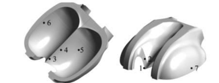
Rossetti et al. [27], classify cavitation in the Pelton bucket into 7 zones as it is given in Figure 10. Region 1 and two damages occur because of the bucket- jet interaction. Region 3 and 4 type cavitation is formed due to the irregularities of the surface, which causes to flow separation, secondary vortices and cavitation. Region 5 type cavitation is originated from both by rain erosion and cavitation. Due to the improper bucket discharge angle zone, 6 and 7 type cavitation occurs.
Figure 10. Erosion location on a Pelton Turbine [21]
2.1.2 Cavitation in propeller turbines
This title is briefly described in Li [24]. In Figure 11(a), discharge factor versus speed factor graph is given. In this graph, possible cavitation regions are given due to the operating ranges like in the Francis turbine. In Figure 11(b), cavitation zones are given upon the turbine blade.
Four main types of cavitation are defined in Li [24] as it is seen in Figure 11 (a), in the operating range one which is seen in high discharge values cavitation seen in the suction side of the blade. In range 2, draft tube swirl occurs with the same reasons of the Francis turbine draft tube swirl cavitation. In the operating range 3, cavitation occurs in the leading edge of the blade. In the operating range 4, unlike the 3rd range, cavitation occurs in the pressure side of the blade. 3rd and 4th type of cavitation does not occur if the blade is designed properly. According to Li [24], in the partial operation, circumferential velocity component decreases due to the blade angle adjustment, therefore, draft tube swirl (2) does not occur. For Kaplan turbines, the most important situation is cavitation in the full load range.
Also, clearance cavitation is one of the important problems in the Kaplan turbines. Because of the adjustable runner blades, there is no shroud of the runner, and According to Motycak et al. [28], there is a gap between the runner blades and the runner chamber, which causes clearance cavitation. Motycak et al. [28], classified clearance cavitation in Kaplan turbines in two types. First one is tip clearance cavitation which occurs in the tip of the blade. Gap velocities increase out of control and pressure decreases below the vapor pressure, so the tip clearance cavitation occurs. The second type is tip vortex cavitation. When the tip flow leaves the gap, a jet flow occurs, when this jet leaves the suction side of the runner blade tip vortex is created. Tip clearance and tip vortex cavitation do not affect the critical sigma value, and they do not decrease the efficiency. On the other hand, hub cavitation and leading edge cavitation can be hazardous for Kaplan turbines, which decrease the efficiency.
In Section 3 and 4 several studies about cavitation in hydraulic turbines using experimental and numerical methods are summarized in detail. In Table 1, certain researches are classified according to examined turbine type, method, and related field.
Figure 11. (a) Cavitation curves due to the discharge and speed factor [18]
Figure 11. (b) Cavitation formation regions [18]
Table 1. Several technical papers
|
Paper Title |
Turbine Type |
Research Method |
Research Field |
|
Hydro turbine failure mechanisms: An overview [8] |
Pelton & Francis & Kaplan |
Numerical & Experimental |
Cavitation types and prevention |
|
Cavitation of Hydraulic Machinery [24] |
Pelton & Francis & Kaplan |
Numerical& Experimental |
Cavitation of Hydraulic machinery |
|
Numerical analyses of Cavitating Flow in a Pelton Turbine [27] |
Pelton Turbine |
Numerical |
Pitting cavitation on the runner |
|
Kaplan turbine tip vortex cavitation–analysis and prevention [28] |
Kaplan Turbine |
Numerical & Experimental |
Tip Vortex cavitation prevention methods |
|
Detection of cavitation in hydraulic turbines [30] |
Pelton & Francis & Kaplan |
Experimental |
Detection techniques of cavitation |
|
A review of cavitation-erosion resistant weld surfacing alloys for hydroturbines [31] |
Hydraulic turbines |
Experimental |
cavitation erosive resistant material research |
|
Study of silt erosion on performance of a Pelton turbine [32] |
Pelton Turbine |
Experimental |
Effect of silt erosion for different silt laden parameters |
|
Experimental study of cavitation in a Kaplan model turbine [35] |
Kaplan Turbine |
Experimental |
Visualization of tip vortex, cloud, sheet and travelling bubble cavitation |
|
Methods for Vibro-acoustic diagnostics of turbine cavitation [36] |
Kaplan Turbine |
Experimental |
Vibro-acoustic diagnostic of cavitation |
|
An on-line cavitation monitoring system for large Kaplan turbines [41] |
Kaplan Turbine |
Experimental |
Monitoring and analysis of cavitation level |
|
Numerical Investigations of Flow on the Kaplan Turbine Runner Blade Anticavitation Lip with Modified Cross Section [39] |
Kaplan Turbine |
Numerical |
Detection and prevention of tip vortex cavitation |
|
Numerical prediction of non-cavitating and cavitating vortex rope in a Francis turbine draft tube [44] |
Francis Turbine |
Numerical |
Prediction of Vortex rope in a draft tube |
|
Numerical Simulation and analysis of pressure pulsations in Francis hydraulic turbine with air admission [42] |
Francis Turbine |
Numerical & Experimental |
Air admission effect to pressure pulsation in the draft tube |
|
A case study in selective visualization of unsteady 3D flow [47] |
Kaplan Turbine |
Numerical |
Visualize the cavitation regions near the runner blades |
|
Effect of cavitation in hydraulic turbines- A review [50] |
Pelton & Francis & Kaplan |
Numerical & Experimental |
Literature survey related to cavitation |
|
Dynamics and Intensity of Erosive partial Cavitation [51] |
2D Hydrofoil |
Experimental |
Sheet and cloud cavitation detection |
|
Jet quality and Pelton efficiency [52] |
Pelton Turbine |
Numerical & Experimental |
Correlation of upstream bends and jet dispersion |
|
Development of Pelton Turbine Using Numerical Simulations [53] |
Pelton Turbine |
Numerical & Experimental |
Comparison of numerical and experimental studies |
|
Importance of Jet Quality on Pelton Efficiency and Cavitation [54] |
Pelton Turbine |
Numerical |
Influence of Jet Shape on Performance and Cavitation |
|
Flow in a Pelton Turbine Bucket: Numerical and Experimental Investigations [55] |
Pelton Turbine |
Numerical & Experimental |
Free surface flow in a Pelton turbine model bucket |
|
Prediction and experimental verification of vortex flow in draft tube of Francis turbine based on CFD [56] |
Francis Turbine |
Numerical & Experimental |
Investigation of draft tube vortex rope under different operating conditions |
|
Effect of blade perforation on Francis hydro-turbine cavitation characteristics [57] |
Francis Turbine |
Numerical & Experimental |
Blade perforation effects of cavitation |
|
Experimental analysis of the swirling flow in a Francis turbine draft tube: Focus on radial velocity component determination [58] |
Francis Turbine |
Experimental |
LDV and PIV techniques to calculate radial velocity component |
|
Study of cavitation in hydro turbines- A review [59] |
Francis & Kaplan |
Numerical & Experimental |
Cavitation in reaction turbines |
|
Experimental Determination of Cavitation Characteristics of Hydraulic Turbines [60] |
Francis Turbine |
Experimental |
Detection methods of cavitation |
In the study of the Avellan [29], cavitation types and their effects to efficiency are investigated for centrifugal pumps, Francis turbines, Kaplan and Bulb turbines in the model-testing laboratory. For Francis turbines, in the inverse runner rotation (high flow regime), the large axis-symmetric fluctuating cavity is featured. In the low flow regime, helical shape whirl is observed (Figure 13).
For Kaplan Turbine, at the hub of the runner cavity is formed which is sensitive to the Thoma number. As there is a gap between the blades and the casing, tip clearance cavitation is observed in this yard, which is not very dependent on the Thoma number [29].
Figure 13. Axisymmetric and helical shape whirl for low and high discharge operation for Francis turbines [29]
Escaler et al. [30], carried out an experimental investigation to develop the detection techniques of cavitation in hydraulic turbines. In this study, to detect the cavitation, structural vibration analysis, acoustic emission analysis, hydrodynamic pressure measurements are performed, and visualization techniques are used to visualize the cavitation. Acoustic emission sensors are used in the higher frequencies where accelerometer cannot reach. The results are obtained for various types of turbines. For leading-edge cavitation, measuring of vibration technique is suggested as leading edge cavitation creates heavy vibration. For bubble cavitation, vibration measurement in the guide bearing is suggested. For draft tube swirl, pressure measurement from the draft tube wall is fond as an effective technique.
Hart and Whale [31], carried out work to improve weld surface alloy to resist cavitation erosion in hydroturbines. When cavities are collapse shock waves are produced, and turbine runner surface can approach to 1500 MPa which produce permanent deformation. Repetitive cavities generated shock waves in regular frequency which causes to fatigue stresses. After some time, small cracks develop in the material surface. In this study, the weight loss curves for several alloys are obtained according to the results a material which is named as CaviTec (details of this material is given in the paper) can handle much more stress, and for a long time, no damage occurs.
Padhy and Saini [32] investigate the effect of silt erosion for different silt-laden parameters and operating parameters such as silt concentration, size of silt particles, jet velocity and operating hours of the turbine on efficiency loss in Pelton turbine buckets with experimental test set-up. Details of the methodology of the experiments are given in reference [33]. A runner with 16 buckets is used in the experiments which are made up of brass. It is found that power and efficiency decrease with mass loss. In later stages, efficiency decrease and power loss were found asymptotic. Also, a correlation is developed for percentage efficiency loss as a function of silt concentration, silt particle size, jet velocity and operating hour of the turbine.
Kurusawa et al. [34] carried out a study about the virtual model test for a Francis turbine. A high accuracy prediction method for a Francis turbine is generated, and the entire flow is solved to reduce the numerical errors. Three different specific speed Francis turbines is simulated and tested. Unsteady Reynolds-Averaged Navier-Stokes equations with the Reynolds Stress model and Bubble two-phase flow model is used to solve. The model tests are performed on a test rig at the hydraulic research laboratory in Toshiba Corporation. According to critical cavitation performance comparison between prediction and model test prediction results in the runner, outlet passage is good agreement with the visualization results. Also, Kurosawa et al. verified that the critical cavitation coefficient could be predicted with high accuracy.
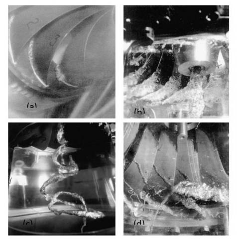
Grakula and Bark [35], performed an experimental working with high-speed filming, video filming and visual observations with stroboscopic light on a Kaplan model turbine at the hydraulic Machines Laboratory of GE Energy (Sweden) AB. According to their results, attached sheet cavities starts at the leading edge are usually the result of a mismatched angle of attack which causes a flow separation close to the leading edge. Also, it is claimed that, by decreasing the cavitation number which means bubble concentration is increased, the traveling bubble cavitation turns to sheet cavitation.
Bajıc [36] carried out noise sampling, signal processing and analysis, and data processing, analysis, and interpretation in vibro-acoustic diagnostics of turbine cavitation. Improvement and new techniques are developed. With these techniques’ early detection of cavitation, extraction of data on cavitation details is possible.
In the study of Nicolet [37], an experimental investigation on a scale model of high specific speed Francis turbines is performed. Draft t tube was equipped with 292 pressure taps also Plexiglas cone is made to visualize the runner outlet. 104 pressure transducers are used in the draft tube wall. According to results, pressure fluctuations at 2.5 fn frequency is identified all along the draft tube walls, the source of those pressure fluctuations being located at the inner part of the draft tube elbow. The full test rig simulation carried out that 2.5 fn frequency value corresponds to an eigen frequency of the system.
Shi et al. [38] carried out an online monitoring system to observe cavitation for large Kaplan turbines. Operating condition and service times of water turbine effects cavitation level. In order to observe the cavitation, an online monitoring system is used. Audible sound (20 Hz-20 kHz) and ultrasound (50 kHz-300 kHz) are monitored via sensors both accelerometers and acoustic emission sensors. Signals from sensors are evaluated. The analyses of the signal characteristics are important to estimate cavitation and the degree of cavitation erosion. Evaluated data is stored and evaluated based on different operating conditions of the turbine which is a water head, wicket gate opening or power output. According to the frequency characteristics, data is classified as mechanical sound water flow sound and cavitation. The cavitation intensity based on an operating condition is monitored, and cavitation erosion degree is compared with analysis.
Motycak et al. [28] focused on the Kaplan turbine runner cavitation with the help of the CFD tools. TurboGrid software is used for mesh generation. According to the study, one of the most important parameters for Kaplan runner mesh generation is using a reasonable number of cells to model the tip clearance. For calculation, Ansys-CFX software is used with the k-ε turbulence model. According to results, to discard the tip vortex cavitation, the runner blade design could be changed by changing the blade camber line deflection. Also designing anti-cavitation lips can significantly reduce the tip vortex cavitation pitting.
Rossetti et al. [27], applied a CFD model to the Pelton turbine to study the cavitation mechanics in the Pelton turbine buckets. The bucket geometry is modeled and analyzed using unsteady RANS multiphase analysis. For calculation Ansys-CFX software is used, to reduce the costs 3 of the buckets are meshed instead of 21. According to numerical results, there are different vapor productions during the cut-in water jet processes by the bucket. Also, a procedure is developed to identify the locations of higher damage risk on the runner.
Cojocaru and co-workers [39] investigated the effects of an anti-cavitation lip on the Kaplan turbine runner blade suction side. In the Romanian hydropower plants, cavitation erosion generally occurs in Kaplan and bulb turbines. An Anticavitation lip is placed on the runner blade suction side to prevent cavitation erosion. The anti-cavitation lip geometry is firstly modeled at original dimensions and made numerical analysis and is seen the cavitation erosion decreased. However erosion occurred on the anti-cavitation lip, so anti-cavitation lip shape and dimensions are modified to reduce erosion, the cross section is changed and anti-cavitation lip edges, both the leading edge and a trailing edge, are smoothed.
Balint et al. [40], performed 3D single-phase flow in Kaplan turbine runner; the secondary phase for water was activated starting far from the cavitation occurrence conditions. The output pressure is decreased until the cavitation occurs in the runner blade. When Thoma number is decreased in order to catch cavitation, firstly suction side cavitation occurs. After filling the whole of the leading edge in the suction side cavitation starts on the blade tip of the suction side and starts to move toward to trailing edge.
Zhang [41], carried out a numerical analysis of cavitating turbulent flow in a high head Francis turbine at partial load operation. A computational grid is generated using ICEM CFD, for the spiral case, stay vanes, guide vanes, runner and draft tube 8.300.000 elements are used. The analysis was performed by OpenFOAM code with the k- w SST turbulence model. According to writers, to observe the cavitating flow, vthe olume fraction of water vapor is an important feature. The tendency of the cavitating flow in the runner and draft tube agrees well with the turbine empirical results.
Qian et al. [42] worked out a 3D unsteady multiphase flow in the whole passage of Francis turbine simulation. Three points are located in the spiral case, the guide vane and the runner to predict pressure pulsations. The CFD simulations are made by a commercial CFD software- Fluent and slide mesh model is used to get accurate time results. The pressure pulsations are analyzed via a Fast Fourier Transform (FFT) and obtained amplitude spectrum. The experimental results corroborate the computational ones. The connection between pressure pulsation and air admission is analyzed. According to results, dominant frequency is decided by the runner frequency, geometry of the runner and draft tube. In the spiral case and the guide vane, the same frequency of draft tube is observed with smaller amplitude. With air admission, dominant frequency is not changed, but amplitude decreases. When there is air admission plane 1 pressure differences decreases, the pressure pulsation in the draft tube transmits upstream and low- frequency pressure pulsation can be found in the spiral case and the guide vane.
Muntean et al. [43] carried out a 3D cavitating flow numerical investigation in Francis turbine. A mixture model is verified on a benchmark problem for the hemispherical give, and the model which is implemented in the Fluent commercial code is used to investigate the cavitation in the Francis turbine runner. First, a steady noncaviatating flow is simulated in a runner interblade channel. Second, using the cavitation model, a3D cavitating flow is investigated in the Francis turbine runner at the maximum load. Based on the results, the local change of the pressure distribution on the blade with and without a cavity is examined. The cavitation affects the runner torque value.
Jost and Lipej [42-46], presented a numerical flow analysis to predict of vortex rope in a draft tube. Pressure fluctuations in the draft tube are the main reason for the vortex, which occurs in the outlet of the runner. Therefore in those papers, the main aim is to predict pressure pulsation amplitude versus different guide vane openings and comparing those with experimental studies. Different turbulence models (SAS-SST, RSM, and LES) are used. Also, grid independency and time step size studies are performed. At partial load, as runner channel is not uniformly fulfilled with the flow, secondary backflow zone is formed near the hub. Instead of cannot predicting the direct connection between the runner geometry and dynamic characteristics of the turbine it is claimed that the shape of the runner channel and the distribution of circumferential and meridional velocity component affect the vorticity formation. According to the turbulence model study, it is claimed that SAS-SST, RSM, and LES models can predict vortex formation when cavitation was not modeled. When cavitation was modeled, LES predictions are more accurate than SAS-SST and RSM models.
Bauer et al. [47], worked out a case study of the visualizing technique for the isolated flow from time-independent data. The aim is to visualize the cavitation regions. The flow structure of the selected region is constructed by a particle seeding scheme based on quasi-random numbers. The selected region is named as a region of interest (ROI). Specifying the region reduces the amount of data to be produced. In order to visualize the flow in ROI a standard particle-based technique is modified. These modifications are made to see particles in the ROI and maintain the particle density of incompressible flow. Using quasi-random sequence when seeding new particles with uniform density, provide non-regular patterns and avoid particle clustering. This method is used to visualize the vortex rope in the draft tube of a Francis turbine and cavitation on the suction side of the turbine and pump runner blades.
Guo et al. [48], investigate the draft tube vortex and its effects on cavitation numerically. For the calculation of cavitating flow Okia et al. [49] is adopted. The formulation of the cavitation model is given below.
$\frac{D{{f}_{L}}}{Dt}=[{{C}_{g}}(1-{{f}_{L}})+{{C}_{1}}{{f}_{L}}](p-{{p}_{v}})$ (2)
In this equation fL is the liquid volume, P is the static pressure, pv is the vapor pressure and C is constant which are given in ref 48. According to results when the only the draft tube is simulated the minimum pressure value is bigger than the vapor pressure. So cavitating flow cannot be observed with only the draft tube case. Due to the runner and draft tube simulation, the minimum pressure at the cone of the runner is lower than the vapor pressure. So to obtain the distribution of velocity and a liquid fraction at the inlet of the draft tube analysis with runner should be done.
According to Knapp et al. [19]’s definition when a body is heated under constant pressure known as boiling, or when it is pressure is decreased under constant temperature known as cavitation, a new state occurs which contains vapor or gas and vapor-filled bubbles. A cavitation phenomenon is seen in many branches of engineering. It can be set in in the machines and the systems which contain sudden pressure and velocity changes. In hydraulic turbines, due to the cavitation; machine performance drops, high and low pressure is produced, vibration level increases and according to high local stress, metallic surface erosions occur. Cavitation cannot be destroyed in hydro turbines; however, minimizing the cavitation and its negative affects are possible. Many investigators, work about the understand cavitation physics through numerical and analytical methods.
•Flow inside the Pelton turbine is a complex phenomenon due to the multiphase (air, water, water vapor), free surface in nature, complex bucket geometry, jet-bucket interaction, and incidence angle. Numerical studies about flow in a Pelton turbine, which are based on the unsteady multi-phase homogenous model are performed by several investigators. According to experimental studies, cavitation and its effects on the performance of Pelton machines can be predicted well with experimental methods. On the other hand, observing the flow distribution inside bucket interference of the jet is not an easy process with experimental methods. In several types of research, both numerical and experimental methods are conducted to investigate the cavitating flow in the Pelton turbine and results show that experimental results match with numerical predictions. Although our understanding of cavitation phenomena is developed in the last years, there are still need experimental and numerical studies.
•Generally, Kaplan type turbines exposed to tip vortex cavitation, cloud cavitation, which is formed in blade tip, sheet cavitation and traveling bubble cavitation, which are formed in blade root. The most hazardous and frequently seen cavitation is tip vortex cavitation. To visualize cavitation experimentally in Kaplan turbines, high-speed filming, video filming and visual observations with stroboscopic light, as a qualitative technique, acoustic emission sensors and accelerometers are used. In order to detect tip vortex cavitation numerically, steady-state simulations are sufficient enough comparing to experimental results. To deal with tip vortex cavitation three main precaution method is recommended which are cavitation free blade design, tip clearance reduction and disposing of anti-cavitation lip.
• For Francis type turbines, both quantitative and qualitative observations are necessary to detect cavitation zone and the type of cavitation. As a quantitative technique, velocity and pressure fluctuations at various locations are measured. As a qualitative technique, draft tube inlet (runner outlet) will be transparent, and visualization of the cavitation becomes possible. Also, a high-speed frame rate camera is placed in the draft tube wall. With this technique, draft tube swirl cavitation can be detected and observed easily. In general, numerical studies are about prediction and prevention of draft tube vortex rope. As numerical methods unsteady RANS, LES and SST turbulence models are used. In order to observe draft tube cavitation, these numerical methods are applied.
With those studies which are summarized in this paper covers much ground about cavitation on the other hand further studies are needed about cavitation in hydro turbines. Numerical methods provide sufficient predictions for cavitation. However, numerical results should be verified by experimental measurements and detection methods to decide what intensity and which shape of cavitation is hazardous and vital, where the local pressure is lower than the vapor pressure and at which static pressure cavities start to grow and collapse.
|
Q |
Flow rate (m3/s) |
||
|
H |
Head (m) |
||
|
NED |
Dimensionless Specific Speed (%) |
||
|
QED |
Dimensionless Flow Rate (%) |
||
|
u,v,w D |
Velocity components (m/s) Diameter (m) |
||
|
Greek symbols |
|||
|
σ |
Dimensionless Thoma Number |
||
[1] World Energy Council, https://www.worldenergy.org/data/resources/resource/hydropower/ accessed on 8 August 2018.
[2] Hydroelectric power, U.S. Department of the Interior, Bureau of Reclamation Power Resources Office, http://www.usbr.gov/power/edu/pamphlet.pdf, accessed 12 July 2014.
[3] Layton ET. Jr. (1979). Scientific technology, 1845-1900: The hydraulic turbine and the origins of American industrial research. The Johns Hopkins University Press and the Society for the History of Technology 20(1): 64-89. https://doi.org/10.2307/3103112
[4] Layton ET. Jr. (1982). Benjamin Tyler and the American antecedents of the hydraulic turbine. The Newsletter of the American Precision Museum 5(3): 15-20.
[5] Fasol KH. (2002). A short history of hydropower control. IEEE Control Systems Magazine 22(4): 68-76. https://doi.org/10.1109/MCS.2002.1021646
[6] Gravitation Water Vortex Power Plants. web site: http://www.zotloeterer.com, accessed on 11.08.2018.
[7] Tanaka Hydropower Co. Ltd. (2016). Tanaka Hydropower Turbine Selection Chart.
[8] Dorji U, Reza G. (2014). Hydro turbine failure mechanisms: An overview. Engineering Failure Analysis 44: 136-147. https://doi.org/10.1016/j.engfailanal.2014.04.013
[9] Drtina P, Sallaberger M. (1999). Hydraulic turbines—basic principles and state-of-the-art computational fluid dynamics applications. Proceedings of the Institution of Mechanical Engineers, Part C: Journal of Mechanical Engineering Science 213(1): 85-102. https://doi.org/10.1243/0954406991522202
[10] Nasir BA. (2013). Design of high-efficiency Pelton turbine for micro hydropower plant. International Journal of Electrical Engineering & Technology (IJET) 4(1): 171-183.
[11] Padhy MK, Saini RP. (2008). A review on silt erosion in hydro turbines. Renewable and Sustainable Energy Reviews 12(7): 1974-1987. https://doi.org/10.1016/j.rser.2007.01.025
[12] Casey MV, Keck H. (1996). Hydraulic turbines. Handbook of Fluid Dynamics and Fluid Machinery, John Wiley.
[13] Okyay G. (2010). Utilization of CFD tools in the design process of a Francis turbine. MSc Thesis, ODTÜ, Ankara, Turkey.
[14] Akin H, Aytac Z, Ayancik F, Ozkaya E, Arioz E, Celebioglu K, Aradag S. (2013). A CFD aided hydraulic turbine design methodology applied to Francis turbines. Power Engineering, Energy and Electrical Drives (POWERENG), 2013 Fourth International Conference on. IEEE. https://doi.org/10.1109/PowerEng.2013.6635694
[15] Ayli E. (2016). Design and parameter optimization of Francis type turbines and development of substructure of model tests by numerical methods. PhD Thesis, TOBB ETU, Turkey.
[16] Zhang M, Valentin D, Valero C, Egusquiza M, Equsquiza E. (2019). Failure investigation of a Kaplan turbine blade. Engineering Failure Analysis 97: 690-700. https://doi.org/10.1016/j.engfailanal.2019.01.056
[17] Javadi A, Nilsson H. (2017). Detailed numerical investigation of a Kaplan turbine with rotor-stator interaction using turbulence-resolving simulations. International Journal of Heat and Fluid Flow 63: 1-13. https://doi.org/10.1016/j.ijheatfluidflow.2016.11.010
[18] Cai SQ. (2019). Cavitation occurring in capillary tubes. Physics Letters A 383(6): 509-513. https://doi.org/10.1016/j.physleta.2018.11.026
[19] Knapp RT, Dally JW, Hammitt FG. (1970). Cavitation. McGraw-Hill, New York.
[20] Brennen CE. (2011). An introduction to cavitation fundamentals. 1-17.
[21] Luo XW, Ji B, Tsujımoto Y. (2016). A review of cavitation in hydraulic machinery. Journal of Hydrıdynamics, Ser. B 28(3): 335-358. https://doi.org/10.1016/S1001-6058(16)60638-8
[22] Hammitt FG. (1980). Cavitation and multiphase flow phenomena. McGraw-Hill Book Co.
[23] Sav M. (2010). Francis Tipi Hidrolik Türbinlerde Kavitasyonun Etkisi. MSc Thesis, Fırat Unıversity, Elazıg, Turkey.
[24] Li SC. (2000). Cavitation of hydraulic machinery. Imperial College Press. https://doi.org/10.1142/p219
[25] Robertson JM, Wislicenus GF. (1969). Cavitation state of knowledge. American Society of Mechanical Engineers.
[26] Jean-Pierre F. (1995). La cavitation: mécanismes physiques et aspects industriels. Grenoble, Presses universitaires de Grenoble PUG.
[27] Rossetti A, Pavesi G, Ardizzon G, Santolin A. (2014). Numerical analyses of cavitating flow in a Pelton turbine. Journal of Fluids Engineering 136(8): 081304. https://doi.org/10.1115/1.4027139
[28] Motycak L, Skotak A, Kupcik R. (2012). Kaplan turbine tip vortex cavitation–analysis and prevention. IOP Conference Series: Earth and Environmental Science 15(3): 2060. https://doi.org/10.1088/1755-1315/15/3/032060
[29] Avellan F. (2004). Introduction to cavitation in hydraulic machinery. Proceedings of HMH 2004, 6th Int. Conference on Hydraulic Machinery and Hydrodynamics, Timisoara, Romania, October 21-22, 2004, pp. 11-22.
[30] Escaler X, Egusquiza E, Farhat M, Avellan F, Coussirat M. (2006). Detection of cavitation in hydraulic turbines. Mechanical Systems and Signal Processing 20(4): 983-1007. https://doi.org/10.1016/j.ymssp.2004.08.006
[31] Hart D, Whale D. (2007). A review of cavitation-erosion resistant weld surfacing alloys for hydroturbines. Eutectic Australia Pty. Ltd., Sydney.
[32] Padhy MK, Saini RP. (2011). Study of silt erosion on performance of a Pelton turbine. Energy 36(1): 141-147. https://doi.org/10.1016/j.energy.2010.10.060
[33] Padhy MK, Saini RP. (2009). Effect of size and concentration of silt particles on erosion of pelton turbine buckets. Energy 34(10): 1477-1483. https://doi.org/10.1016/j.energy.2009.06.015
[34] Kurosawa S, Lim SM, Enomoto Y. (2010). Virtual model test for a Francis turbine. IOP Conference Series: Earth and Environmental Science 12(1): 012063. https://doi.org/10.1088/1755-1315/12/1/012063
[35] Grakula M, Bark G. (2001). Experimental study of cavitation in a kaplan model turbine. Minerva Anesthesiologica. https://doi.org/10.1111/j.1699-0463.1996.tb04903.x
[36] Bajic B. (2010). Methods for vibro-acoustic diagnostics of turbine cavitation. Journal of Hydraulic Research 41(1): 87-96. https://doi.org/10.1080/00221680309499932
[37] Nicolet C, Arpe J, Avellan F. (2004). Identification and modeling of pressure fluctuations of a Francis turbine scale model at part load operation. Proceedings of the 22nd IAHR Symposium on Hydraulic Machinery and Systems Stockholm, Sweden, pp. 1-14.
[38] Shi H, Li Z, Bi Y. (2007). An on-line cavitation monitoring system for large Kaplan turbines. Power Engineering Society General Meeting, 2007. IEEE, pp. 1-6. https://doi.org/10.1109/PES.2007.385723
[39] Cojocaru V, Balint D, Campian VC, Nedelcu D, Jianu C. (2011). Numerical investigations of flow on the Kaplan turbine runner blade anticavitation lip with modified cross section. Recent Researches in Mechanics 374-83. https://doi.org/10.1145/2399187.2399188
[40] Balint D, Resiga R, Muntean S, Ruprecht A, Goede E. (2004). High Performance computing of self-induced unsteadiness for cavitating flows in hydraulic turbomachinery. Romannia: University Politehnica of Timisoara, National Center for Engineering of Systems with Complex Fluids.
[41] Zhang H, Zhang L. (2012). Numerical simulation of cavitating turbulent flow in a high head Francis turbine at part load operation with OpenFOAM. Procedia Engineering 31: 156-165. https://doi.org/10.1016/j.proeng.2012.01.1006
[42] Qian ZD, Yang JD, Huai WX. (2007). Numerical simulation and analysis of pressure pulsation in Francis hydraulic turbine with air admission. Journal of Hydrodynamics, Ser. B 19(4): 467-472. https://doi.org/10.1016/S1001-6058(07)60141-3
[43] Muntean S, Bernad S, Susan-Resiga R, Anton I. (2003). Three-dimensional cavitating flow in hydraulic Francis turbines. Workshop on Numerical Methods in Fluid Mechanics and FLUENT Applications, At Timisoara, Romania.
[44] Jošt D, Lipej A. (2011). Numerical prediction of non-cavitating and cavitating vortex rope in a Francis turbine draft tube. Strojniški vestnik-Journal of Mechanical Engineering 57(6): 445-456. https://doi.org/10.5545/sv-jme.2010.068
[45] Lipej A, Jost D, Meznar P, Djelic V. (2009). Numerical prediction of pressure pulsation amplitude for different operating regimes of Francis turbine draft tubes. International Journal of Fluid Machinery and Systems 2(4): 375-382. https://doi.org/10.5293/IJFMS.2009.2.4.375
[46] Jošt D, Lipej A. (2009). Numerical prediction of the vortex rope in the draft tube. 3rd IAHR International Meeting of the Workgroup on cavitation and Dynamic Problems in Hydraulic Machinery and Systems.
[47] Bauer D, Peikert R, Sato M, Sick M. (2002). A case study in selective visualization of unsteady 3D flow. Proceedings of the conference on Visualization'02. IEEE Computer Society. https://doi.org/10.1109/VISUAL.2002.1183821
[48] Guo Y, Kato C, Miyagawa K. (2007). Large-eddy simulation of non-cavitating and cavitating flows in the draft tube of a Francis turbine. SEISAN-KENKYU 59(1): 83-88. https://doi.org/10.11188/seisankenkyu.59.83
[49] Okita K, Kajishisma T. (2002). Numerical simulation of unsteady cavitating flows around a hydrofoil. Trans. JSME, Series B 68(667): 637-644. https://doi.org/10.1299/kikaib.68.637
[50] Khurana SN, Hardeep S. (2012). Effect of cavitation in hydraulic turbines- A review. International Journal of Current Engineering and Technology 172-177.
[51] Escaler X, Farhat M, Egusquiza E, Avellan F. (2007). Dynamics and intensity of erosive partial cavitation. Journal of Fluids Engineering 129(7): 886-893. https://doi.org/10.1115/1.2742748
[52] Staubli T, Abgottspon A, Weibel P, Bissel C, Parkinson E, Leduc J, Leboeuf L. (2008). Jet quality and Pelton efficiency. Proceedings of the IGHEM, International Conference on Hydraulic Efficiency Measurements, 2008, Italy.
[53] Patel K, Patel B, Yadav M, Foggia T. (2010). Development of Pelton turbine using numerical simulation. 25th IAHR Symposium on Hydraulic Machinery and Systems, pp: 1-8. https://doi.org/10.1088/1755-1315/12/1/012048
[54] Peron M, Parkinson E, Geppert L., Staubli T. (2008). Importance of jet quality on Pelton efficiency and cavitation. International conference on Hydraulic Efficiency Measurements, 2008, Mılano.
[55] Perrig A, Avellan F, Kueny JL, Farhat M, Parkinson E. (2006). Flow in a Pelton turbine bucket: Numerical and experimental investigations. Journals of Fluids Engineering 128(2): 350-358. https://doi.org/10.1115/1.2170120
[56] Zeng Y, Liu X, Wang H. (2012). Prediction and experimental verification of vortex flow in draft tube of Francis turbine based on CFD. International Conference on Advances in Computational Modeling and Simulation 31: 196-205. https://doi.org/10.1016/j.proeng.2012.01.1012
[57] Zhu XZ, Su WT, Li BX, Li CF, Guo L. (2014). Effect of blade perforation on Francis hydro-turbine cavitation characteristics. Journal of Hydraulic Research 52(3): 415-420. https://doi.org/10.1080/00221686.2013.879610
[58] Tridon S, Barre S, Ciocan GD, Tomas L. (2010). Experimental analysis of the swirling flow in a Francis turbine draft tube: Focus on radial velocity component determination. European Journal of Mechanics 29(4): 321-335. https://doi.org/10.1016/j.euromechflu.2010.02.004
[59] Kumar P, Saini RP. (2010). Study of cavitation in hydro turbines- A review. Renewable and Sustainable Energy Reviewa 14(1): 374-383. https://doi.org/10.1016/j.rser.2009.07.024
[60] Demirel G, Ayli E, Celebioglu Y, Tascioglu Y, Aradag S. (2015). Experimental determination of cavitation characteristics of hydraulic turbines. World Congress of Engineering, 2015, England.