OPEN ACCESS
Perforated fins, because of their compactness, low weight and high effectiveness are widely used in heat sinks to enhance the heat transfer from electronic equipments. The innovative form of the perforated fin (with inclination angles) was considered for the rectangular pin fin. In the analytical solution, the Degenerate Hypergeometric Equation (DHE) was used as a new derivative method and then solved by Kummer’s series. Also, Signum function is used to model the opposite and mutable approach heat transfer area. This article presents a combined open literature and Experimental work of various cases to validate the analytical study. Two models were perforated experimentally at the 5mm from bottom tip at a various inclination angles by using a wire cut electrical discharge machining (Wire EDM) and EDM drilling machine. The present mathematical model has good reliability according to the high agreement of the validation results about (0.33%- 1.4%). It was found that use of the inclined perforation fin leads to decreased thermal resistance and improvement in the thermal performance of the pin fin by enhancing the heat transfer. Also, the optimization can be achieved by minimizing the weight and length of the pin fin based on the Multi advantages of the present model. Likewise, Entropy generation was minimized with increases the open area ratio at a certain Rayleigh number and constant heat flux.
fin, incline perforation, natural convection, degenerate hypergeometric equation, optimization, entropy minimization
Today, heat transfer increase as a result of development in the different applications (communications devices, Mechatronics application, and different electronic devices). For this reason, the investigators used the perforation towards straight direction to improve the overall performance of the heat sinks. Moreover, the changes of the shapes, sizes, numbers and orientation of the perforations were adopted to optimize the thermal performance.
Computational technique is used by the most investigators to solve the governing equations. Five cases with single perforation and three cases with multiple perforations of an annular finned-tube system were evaluated to find the best performance by [1] in extreme climatic conditions, a single perforation location at 120o provided the favorable results. Also, the enhancement of the heat transfer can be reached to the 5.96%. Circular, rectangular and trapezoidal cross section area of the perforation was studied by [2] to find the effects of the number and geometry of the hollow fin on the heat transfer through rectangular fins attached to microchannel heat sink, results show the improvement is strongly depends on the numbers of the hollows and negligible influence of the hollow geometry. To show the advantages of the perforation, [3] shows The thermal profile of the perforated fins in a staggered manner performs better than the solid elliptical pin fin according to the Static temperature, Nusselt number and total heat that is calculated. The effects of the porosity on the performance of the fins were investigated by [4,5]for longitudinal and lateral perforation. Rectangular cross section with different dimensions and multi numbers of the perforation was considered to show the thermal enhancement at various operating conditions. Higher performances for perforated fins are observed. Also the increased effectiveness by increasing porosity ratio. The Nusselt Number and the friction factor were optimized separately and together for the circular perforated of the rectangular cross section by [6], the results show the higher thermal performance of the pin fin dependent on the lower clearance ratio and lower inter-fin spacing ratio also the efficiency can be increased by 1.1 and 1.9 based on the Reynolds numbers. Likewise, the pin fin efficiency of the circular cross section can be increased by 1.4 and 1.6 by using the circular perforation and the Nusselt number having inversely proportional to the clearance ratio and inter-fin spacing ratio according to [7,8] . A copper material possesses higher thermal conductivity when compared with other material by [9], also a large number of perforated were given the higher heat transfer coefficient. While, the larger hollow pin diameter ratio, offered higher augmentation factor for upward orientation, and the situation was reversed for sideward orientation for the circular pin fin using the circular perforation that are studied by [10].
The Reynolds number and size of perforation have a larger impact on the Nusselt number for rectangular fin using the lateral perforations (square and circular) that are presented by [11]. Perforated pin fin in the cylindrical channel was tested by change the number of a circular perforation, The results show the number of perforations has the significant increase of the convective heat transfer about (30% to 40%) [12].
Other investigations found the temperature distribution of perforated fin by analytical study, [13] reached to the temperature distribution equation of perforated flat plate based on the mathematical model that solved by Fourier series and Flocke’s theory. [14] reported the decrease of thermal conduction resistance of pin fin due to triangular perforation, which leads to improved the heat dissipation that calculated by use variation approach, finite element techniques. Likewise, [15] applied the same technique to find the effects of the orientations of the rectangular perforations under natural convection, the results show the inclined orientation is better for low each of the thickness and thermal conductivity while the parallel orientation is better for higher thickness. Also, [16] concluded to enlarge of perforated size and increase the thermal conductivity leads to augmentation the heat transfer from the rectangular fin.
In [17] the optimization of the thermal resistance was performed on pin-fin heat sinks with a constant Reynolds number. The results show increased the number of the fin leads to decrease the thermal resistance without limit for height (40 mm) while the optimum number of fins can be found at the height (20mm and 30mm). Furthermore, the entropy generation was calculated as another way to optimize. The results show the highest entropy generation with highest Reynolds number, also entropy generation was decreased with the open area ratio increase.
[18] Used the Momentum and energy equations to calculate the entropy generation for rectangular cavities under natural convection, at five aspect ratios and five Rayleigh numbers. The results show the entropy generation increases linearly with aspect ratio and Rayleigh number, also entropy generation was increased by the Rayleigh number at a certain aspect ratio. Likewise [19] investigated the effects of the channel aspect ratio, fin spacing ratio and heat sink material on the entropy generation rate of the microchannel heat sink. The results indicate that, the increases in volume flow rate lead to increase the optimum channel aspect and fin spacing as a results to decrease in thermal resistance.
All recent studies, used the straight perforation with different shapes, sizes and orientations for improving the overall performance of the rectangular plate, pin and annular fins. New approach introduced in this article, by proposing two novelty points, firstly at geometric model, the incline perforation is considered. Secondly, at Analytical process, the new differential technique is used to derive the general form of the temperature distribution regardless of the perforation shape. Also, used the mathematical technique for modeling the opposite and the mutable approach of the heat transfer area. Then used the presented model to study the effects of the parameters on the thermal performance with optimize the model by using the entropy generation minimization.
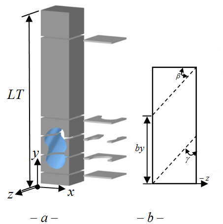
The incline perforated region of the pin fin is shown in Figure 1. In the general form, an undefined section of perforation was considered. Inclination started from ($\beta=0$) at straight perforation. The fin has a rectangular cross section area with single inclined perforated and the base fin is located on the x-z plane. Due to the incline perforation, the heat transfer area is changing with y-direction as well as change with the inclination angle.
Figure 1. a- Fin with single inclined perforated. b- side view.
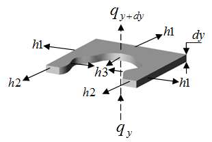
Figure 2. Element description
Energy balance is applied to the element shown in Figure 2, to obtain the differential equation of energy (1) in the perforated region.
In this study, heat transfer analysis relies on a set of assumptions [ Steady heat conduction with no heat generation, One-dimensional heat transfer analysis depended on the impairment of the Biot number at z-axis and x-axis, Constant conductivity $(k=222 \mathrm{W} / \mathrm{m} \cdot \mathrm{K},(\mathrm{A} 1050))$, Constant base temperature, Insulation tip fin, radiation effects are neglected, Uniform ambient temperature and uniform convection heat transfer coefficient and convection coefficient is divided into three types (external non-perforated (h1), external perforated (h2) and internal perforated (h3)].
$\frac{d}{d y}\left(A_{c o n d} \frac{d \theta}{d y}\right) d y=\left[h 1 P_{c o m 1}+h 2 P_{c o m 2}+h 3 P_{c o m 3}\right]$
$\frac{\theta d y}{k}, \theta=T(y)-T_{a i r}$ (1)
where Acond is the conduction area, Pconv is the perimeter of the convection. Various convection heat transfer coefficients were appeared due to incline perforation. Moreover, Convection coefficients depended on the properties of cooling fluid, specifications of the perforated fin and the open perforated ratio (ROP). ROP represents the ratio of actual perforated area to maximum perforation effects.
Empirical correlations for the Nusselt number (Nu) from [20,21] were used to find the convection coefficients h1 and h2 respectively. While the correlation from [22] was modified to become useful for calculated the h3 as described in [23]. Furthermore, temperature distribution of the solid regions was calculated according to reference [20].
Equation (1) can be represented by use the Degenerate Hypergeometric Equation(DHE) [23,24].
$\vartheta \frac{d^{2} u}{d \vartheta^{2}}+(k u 1-\vartheta) \frac{d u}{d \vartheta}-(k u 2) u=0$ (2)
where: $u=e^{\vartheta / 2} G, \vartheta=\xi^{2} \sqrt{p 1}, \theta=G / \sqrt{A_{c o n d}}, \xi=y+\frac{p 2}{2 p 1}$, $k u 1, k u 2$= constants.
The DHE equation (2) was solved by Kummer’s series [25,26]to get the general solution of the present model.
$\begin{aligned} u(\vartheta)=& C O_{i} \varphi(k u 1, k u 2, \vartheta)+\\ & C O_{i+1} \psi(k u 1, k u 2, \vartheta) \quad, i=1,3,5, \ldots \end{aligned}$ (3)
where:
$\varphi, \psi$= confluent hypergeometric function of the first kind and second kind, respectively.
CO= Constant for the general solution.
Boundary conditions, for the constant base temperature:
$\left.u\right|_{\vartheta=\frac{p 2^{2}}{4 p^{3 / 2}}}=\theta_{b} \sqrt{A_{b}} e^{\frac{p 2^{2}}{8 p 1^{3 / 2}}} \quad,\left.\frac{d u}{d \vartheta}\right|_{\vartheta=\left(L P+\frac{p 2}{2 p 1}\right)^{2} \sqrt{p 1}}=0$
Solve of the equation (3) with above boundary conditions, which leads to the temperature distribution equation. $p 1,2, \ldots$(constant) from ref.[23].
$\left[\zeta 10 \varphi\left(k u 1, k u 2,\left(\left(y+\frac{p 2}{2 p 1}\right)^{2} \sqrt{p 1}\right)\right)-\zeta 11 \psi\left(k u 1, k u 2,\left(\left(y+\frac{p 2}{2 p 1}\right)^{2} \sqrt{p 1}\right)\right)\right]$ (4)
$\zeta 10=\frac{\zeta 4 \zeta 6+\zeta 8 \zeta 9}{\zeta 1 \zeta 2(\zeta 4 \zeta 6+\zeta 8 \zeta 9)-\zeta 1 \zeta 3(\zeta 4 \zeta 5+\zeta 7 \zeta 9)}$
$\zeta 11=\frac{\zeta 4 \zeta 5+\zeta 7 \zeta 9}{\zeta 4 \zeta 6+\zeta 8 \zeta 9} \zeta 10, \zeta 1=\frac{e^{-\frac{p 2^{2}}{8 p 1^{3 / 2}}}}{\sqrt{A_{b}}}$
$\zeta 2=\varphi\left(k u 1, k u 2 ; \frac{p 2^{2}}{8 p l^{3 / 2}}\right)$
$\zeta 3=\psi\left(k u 1, k u 2 ; \frac{p 2^{2}}{8 p 1^{3 / 2}}\right)$, $\zeta 4=\frac{\frac{-\left(L P+\frac{p 2}{2 p 1}\right)^{2} \sqrt{P 1}}{2}}{\sqrt{A_{\text {cond.}} )_{L P}}}$,
$\zeta 5=\varphi^{\prime}\left[k u 1, k u 2 ;\left(\left(L P+\frac{p 2}{2 p 1}\right)^{2} \sqrt{p 1}\right)\right]$,
$\zeta 6=\psi^{\prime}\left[k u 1, k u 2 ;\left(\left(L P+\frac{p 2}{2 p 1}\right)^{2} \sqrt{p 1}\right)\right]$,
$\zeta 7=\varphi\left(k u 1, k u 2 ;\left(\left(L P+\frac{p 2}{2 p 1}\right)^{2} \sqrt{p 1}\right)\right)$,
$\zeta 8=\psi\left(k u 1, k u 2 ;\left(\left(L P+\frac{p 2}{2 p 1}\right)^{2} \sqrt{p 1}\right)\right)$,
$\,\,\zeta 9=-\frac{1}{{{A}_{cond}}{{)}_{LP}}}\left[ (LP+\frac{p2}{2p1})(\sqrt{p1}\sqrt{{{A}_{cond}}{{)}_{LP}}}\,)\,\,{{e}^{\frac{-{{(LP+\frac{p2}{2p1})}^{2}}\sqrt{P1}}{2}}}\,-\frac{{{{{A}'}}_{cond.}}{{)}_{LP}}\,\,{{e}^{\frac{-{{(LP+\frac{p2}{2p1})}^{2}}\sqrt{P1}}{2}}}}{2\,\sqrt{{{A}_{cond}}{{)}_{LP}}}}\, \right]\text{ }$
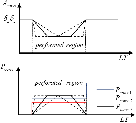
The change of the heat transfer area (Conduction area $A_{c o n d .}$ and convection perimeter $P_{\text { conv. }}$) is depending on the two parameters (y-axis and inclination angle), which leads to many difficulties when calculated the area at any specification. Likewise, the extreme ends for $A_{c o n d .}$ and $P_{\text { conv. }}$ can be represented by a point or by a line depended on the inclination angle and the size of the perforation as shown in figure (3).
Figure 3. Change of the heat transfer area a) conduction area and b) convection perimeter
Signum function (sgn) [27] is used to represent the opposite and the mutable approach of variables $A_{c o n d .}$ and $P_{\text { conv. }}$ with the y-axis as described in Ref.[23]. The results of the two models (I and II) are calculated for the natural convection heat transfer and Rayleigh number (Ra=106) by using the Language of Matlab (R2014a). Geometry specification are (cross section area=.01*.01 m2, fin length = 0.05 m ). Perforation area is 0.007*.007m2 and 0.008*.008 m2 for the model I and model II, respectively.
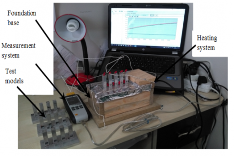
6.1 Experimental Set-Up
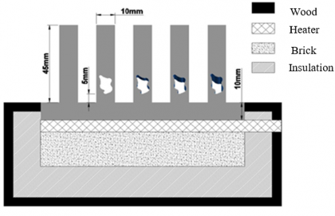
The experimental work set-up including of the foundation base, test models, heating system and measurement devices. Foundation base constructed from wood of 15 mm thickness, fire brick of 47 mm thickness and thermal insulation (see Figure 4a).
Figure 4a. Components of the present model
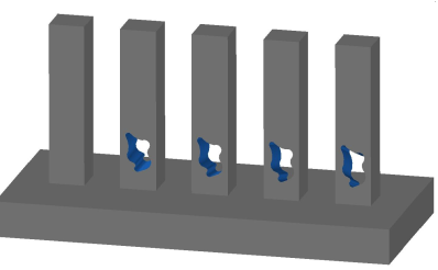
Figure 4b. Test model
The test models consisting of the pin fins and base plate (see figure 4b). All the components are made of the Aluminum (AL-6130). The pin fins had a rectangular cross section of 10mm×10mm, length 45mm and constant spacing of 10mm was made between the pin fins. While, the base plate had dimensions of (length 11cm, width 5cm and thickness 1cm).
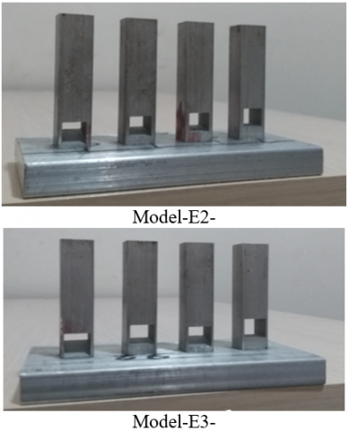
The two models were perforated at the 5mm from bottom tip by (7mm and 8mm) as shown in figure (5). Each model contains four or five pin fins as described in the table (1).
Figure 5. Models for experimental work
Table 1. Specifications of the experimental models
|
Models No. |
Fins specifications |
|||
|
E2 |
Single rectangular perforation with cross area (7mm × 7mm) |
|||
|
$\beta=0^{\circ}$ |
$\beta=8^{\circ}$ |
$\beta=15^{\circ}$ |
$\beta=22^{\circ}$ |
|
|
E3 |
Single rectangular perforation with cross area (8mm × 8mm) |
|||
|
$\beta=0^{\circ}$ |
$\beta=9^{\circ}$ |
$\beta=17^{\circ}$ |
$\beta=25^{\circ}$ |
|
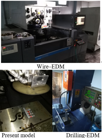
Perforations were made by using a wire cut electrical discharge machining (Wire EDM) and EDM drilling machine as shown in figure (6). EDM technique was used to produce precision parts that match the shape and dimensions perforations of present model.
Figure 6. Machines work
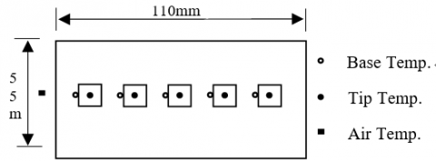
Heater with specifications (40W,AC,240V,50Hz) was used as a heating system. The temperatures were measured by Two Nicle-chromium / Nicle-Aluminum thermocouples for each pin fin and single thermocouple for surrounding temperature as shown in figure (7).
Figure 7. thermocouples locations
6.2 Experimental data
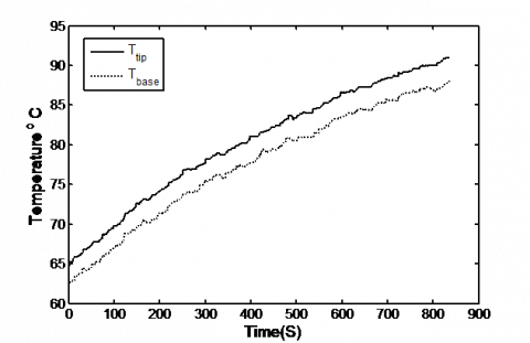
The reading of thermocouples was recorded using a computer via a data-acquisition card of the thermometer (K-type CEM) with 4 channels data logger as shown in figure (8). Before the experimental work, thermocouples were calibrated by using the thermostat to ($\pm 0.2^{\circ} \mathrm{C}$) deviation. The range and accuracy with some details of the thermocouples are presented in table (2). Temperature with time was recorded for each case from less than 65 oC to 91 oC as shown in figure (9).
Table 2. Measuring instrument
|
Model |
Range |
Accuracy |
|
K-type |
-200 oC-1372 oC |
[0.15$\%$ rg $d$oC] |
Figure 8. The picture of the experimental set-up
Figure 9. Variation of the Temperature with the time of the model -1- ($\beta=0^{\circ}$)
7.1 Validation of analytical model
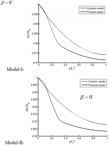
In this study, two validation ways are considered. Formula from [13] is used within the first method to validate the straight perforation. Kirpikov in [13], derived the temperature distribution along the perforated fin is a function of the Biot number. Equation to calculate the Biot number of the present model describe as:
$\begin{aligned} B i &=\frac{L T^{2}\left[\sum h_{i} A_{\text {convi}}\right]}{k \int A_{\text {cond}} d y} \\ i &=1,2,3 \end{aligned}$ (5)
The high similarity between the results are shown below the perforation region, but a spacing was increased between the results in the perforation region. Maximum difference can be reached to (0.60%) as shown in figure (10). Furthermore, above the perforation region the results spacing was decreased. The reasons of the spacing of results can be explained as follows:
1-In Kipikov model, heat transfer coefficient was not classified into three regions.
2- In Kipikov model, approximate solution (Fourier series) was adopted.
3- In Kipikov model, convection coefficient of inner surface was assumed as a ratio from the external coefficient (not depended on the size and length of the perforation).
Figure 10. Comparisons between present model and Kirpikov model for rectangular perforation
The temperature difference was dropped with the inclination angle. Also, the additional drop of temperature can happen with the increase each of the size and number of perforations. The reason of that, increased of the Biot number as a result of enhancement in the thermal resistance of the perforated fin.
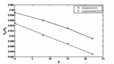
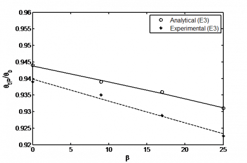
In the second way of the validation, experimental results were used to validate the analytical model by using the dimensionless temperature of the fin tip. The experimental results, shown in figures (11 and 12) are compared with analytical solution for models E2 and E3 respectively. The comparison of the results refers to the good agreement with range of deviations (1.1% -1.4%). Therefore, the analytical modeling is confirmed to be reliable.
Figure 11. Comparison between analytical and experimental work of model-E2.
Figure 12. Comparison between analytical and experimental work of model-E3.
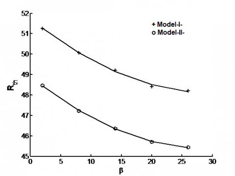
7.2 Effects of inclination (thermal resistance)
The heat transfer area was changed due to the inclined perforation. Which leads to variable thermal resistance (Rth) along the fin length. According to the insulted fin tip, equation to calculate the thermal resistance described as:
$R_{t h}=\frac{A_{conv}}{\int \sqrt{h p k A} d A_{c o n v} \tanh \left(\frac{\int \sqrt{h p / k A} d A_{conv}}{A_{conv}} L T\right)}$
$A_{conv .}=\int_{0}^{L T}\left(P_{c o n v 1}+P_{c o n v 2}+P_{c o n v 3}\right) d y$ (6)
In inclined perforation region, the conduction area was replaced by the convection area, which leads to improve the thermal resistance. Figure 13 shows the change of the thermal resistance with inclination angles for single perforation. All results are shown the decreases of the thermal resistance with an increase for each of the inclination angle and perforation size.
Figure 13. Variation of the Rth with inclination angle.
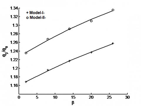
Figure 14. Effects of inclination angles on the heat transfer ratio.
7.3 Effects of the inclination (Heat ratio)
Heat transfer is possible to increase, according to the multi advantages that are obtained from incline perforation and decreases in the temperature distributions along the fin. The heat transfer ratio $q_{p} / q_{s}$ is described as the ratio between the heat transfer of a perforated fin to heat transfer of the solid fin at the same properties.
$q_{p \text { or } s}=-k A_{b}\left.\frac{d \theta}{d y}\right|_{y=0}$ (7)
The increase of the temperature slops with the inclination angle leads to improved the heat transfer ration about (1.16-1.33) times based on the size of perforations as shown in figure (14).
One of the goals of this work was finding the new geometry of the pin fin that would minimize the (fin length and fin weight) while maximize the heat transfer. The optimization was performed on a pin fin with two sizes of perforation and various inclination angles at constant base temperature.
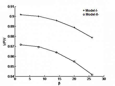
8.1 Minimizing of the fin weight
Minimize the expenditure of fin material can be achieved by using the perforation. Furthermore, this advantage can be increased when using the inclined perforation as a result to decrease the conduction area as shown in figure 15. The results show minimize of the fin weight (MFW) with an increase of the inclination angle and size of perforation. Because all these parameters lead to increase the convection surface area by reducing the conduction heat transfer area.
$M F W=\frac{W_{s}-W_{p}}{W_{s}}$ (8)
where: Ws=weight of solid fin ; Wp=weight of perforated fin
Figure 15. Minimizing of the fin weight with the inclination angle
Figure16. Variation of the length ratio with inclination angle
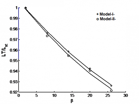
8.2 Minimizing the fin length
In this step, the amount of the heat transfer and fin dimensions for straight perforation was taken as a main design. Then, the fin length can be calculated according to the equation (6). The length ratio (LT/Lst) between the model length and fin length of the straight perforated was calculated. The figure 16 shows the decreases of the length ratio with an increase of the inclination angle. Also, the length ratio has big sensitivity for the inclination angle, while it is change smoothly with the change of the perforated size.
From previous results, the ability of the fin to transfer heat was increased with inclination angle as a result to decrease the thermal resistance. Which leads to minimize the fin length that is required to transfer the same amount of heat by increase each of the inclination angle and size of perforations.
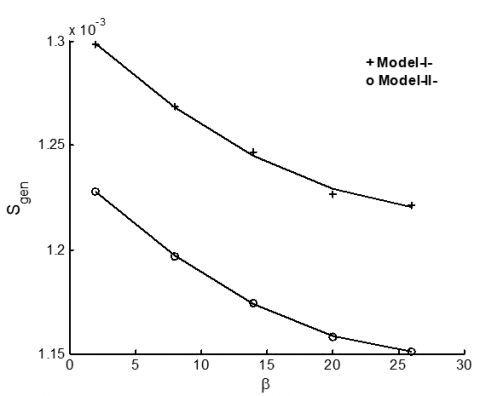
The goal of this step was to minimize the entropy generation that would relate to the incline perforated at various conditions. To show the effects of the inclination angle on the entropy generation, the constant heat flux at base fin was considered. For steady state, the second law of thermodynamics can be written as [28].
$S_{g e n}=m^{\bullet} \Delta S-\iint_{A} \frac{q_{conv} d A}{T(y)}$ (9)
According to the concept of Enthalpy change, entropy generation can be calculated by the equation (10).
$S_{g e n}=\iint_{A} \frac{q_{c o n v}\left(T(y)-T_{a i r}\right) d A}{T(y) T_{a i r}}-\frac{m^{\bullet} \Delta P}{\rho T_{air}}$ (10)
From the above equation, entropy generation is a function of both thermal resistance and pressure drop. For low velocity conditions, the second term can be neglected [28,29].
The figure 17 shows the decreases of the entropy generation with an increase in the inclination angle and perforation size.
Figure 17. Variation of the Sgen with inclination angle.
This paper presented the incline perforating as a new approach to improve the performance of the pin fin. In the solution process, two novel methods were presented: modeling of the opposite approach of the variable heat transfer area based on Signum function and solves energy differential equation by (DHE). For verification of the accuracy level and flexibility of the mathematic model, rectangle cross section area of the perforation with multi size and multi angles were considered. The high agreement of the validation results leads to being sure; the present mathematic model has big reliability. Consequently, general solution of the present study taken as the basis to resolve any perforation shape based on modeling of the heat transfer area. Increase each of the inclination angle and size of perforations which leads to decrease the temperature of the fin as a result of the many advantages (Increase of the inner convection area, Distribute the inner convection area on the longer length in the y-axis and Increase of the external perforated area).
It was found that use of the inclined perforation fin leads to decreased thermal resistance and improvement in the thermal performance of the pin fin by enhancing the heat transfer.
The effect of the parameters (inclination angle and size of perforations) can be used to optimize the present model by maximizing the heat transfer area and minimizing the weight fin. The ability of the fin to transfer heat was increased with the inclined perforation, which leads to minimize the fin length that is required to transfer the heat of the straight perforation.
Entropy generation was minimized with an increase in the inclination angle and perforation size for constant heat flux. However, the optimum point does not appear with the range of the inclined angle that are adopted in this study.
A : Fin cross section area (m2)
bx : Width of rectangular perforated
by : Height of perforated
h : Convection coefficient (W/m2. °C)
LP : Length of the perforated region on y-axis (m)
LT : Total fin length (m)
m· : Mass flow rate (kg/s)
P : Perimeter
q : Heat transfer (W)
S : Entropy (W/ K)
T : Temperature (°C)
Subscripts
gen : Generation
p : Perforated
s : Solid
st : Straight perforated
Greek letters
$\beta, \gamma$: Inclination angles (degrees)
[1] Banerjee R.K., Karve M., (2012). Evaluation of enhanced heat transfer within a four row finned tube array of an air cooled steam condenser, Numerical Heat Transfer, Part A, Vol. 61, pp. 735–753. DOI: https://doi.org 10.1080/ 10407782 .2012 .667649
[2] Tan H.J.T., M.Z. Abdullah, Mujeebu M.A. (2013). Effects of geometry and number of hollow on the performance of rectangular fins in microchannel heat sinks, J. of Thermal Science and Technology, TIBTD Printed in Turkey, Vol. 33, No. 1, pp. 01-09.
[3] Baruah M., Dewan A., Mahanta P. (2011). Performance of elliptical pin fin heat exchanger with three elliptical perforations, CFD Letters, Vol. 3, No. 2, pp. 65-73.
[4] Shaeri M.R., Yaghoubi M. (2009). Thermal enhancement from heat sinks by using perforated fins, Energy Conversion and Management, Vol. 50, pp. 1264-1270. DOI:10.1016/j.enconman.2009.01.021.
[5] Shaeri M.R., Yaghoubi M., Jafarpur K. (2009). Heat transfer analysis of lateral perforated fin heat sinks, Applied Energy, Vol 86, pp. 2019-2029. DOI. 10.1016/j.apenergy.2008.12.029
[6] Sahin B., Demir A. (2008). Performance analysis of a heat exchanger having perforated square fins, Applied Thermal Engineering, Vol. 28, pp. 621-632. DOI. 10.1016/j.applthermaleng.2007.04.003
[7] Sahin B., Demir A. (2008). Thermal performance analysis and optimum design parameters of heat exchanger having perforated pin fins, Energy Conversion and Management, Vol. 49, pp. 1684-1695. DOI. 10.1016/j.enconman.2007.11.002
[8] Dhumne A.B., Farkade H.S. (2013). Heat transfer analysis of cylindrical perforated fins in staggered arrangement, International Journal of Innovative Technology and Exploring Engineering, Vol. 2, No. 5. pp. 225-230.
[9] Bahadure S.D., Gosavi G.D. (2014). Enhancement of natural convection heat transfer from perforated fin, International Journal of Engineering Research, Vol. 3, No. 9, pp. 531-535.
[10] Elshafei E.A.M. (2010). Natural convection heat transfer from a heat sink with hollow/perforated-circular pin fins, Energy, Vol. 35, pp. 2870-2877. DOI. 10.1016/j.energy.2010.03.016
[11] Dhanawade K.H., Sunnapwar V.K., Dhanawade H.S. (2014). Thermal analysis of square and circular perforated fin arrays by forced convection, International Journal of Current Engineering and Technology, Special Issue-2, pp. 109-114. DOI. 10.14741/ijcet/spl.2.2014.20
[12] Fule A., Salwe A.M., Sheikh A.Z., Wasnik N. (2014). Convective heat transfer comparison between solid and perforated pin fin, International Journal of Mechanical and Robotics Research, Vol. 3, No. 2, pp. 384-389.
[13] Kirpikov V.A., Leifman I.I. (1972). Calculation of the temperature profile of a perforated fin, Institute of Chemical Apparatus Design, Moscow, Vol. 23, No. 2, pp. 316-321.
[14] AlEssa A.H.M. (2009). One-dimensional finite element heat transfer solution of a fin with triangular perforations of bases parallel and towered its base, Arch. Appl. Mech., Vol. 79, pp. 741-751. DOI 10.1007/s00419-008-0250-5
[15] Al-Essa A.H., Al-Hussien F.M.S. (2004). The effect of orientation of square perforations on the heat transfer enhancement from a fin subjected to natural convection, Heat and Mass Transfer, Vol. 40, pp. 509–515. DOI. 10.1007/s00231-003-0450-z
[16] Kumbhar D.G, Sane N.K., Chavan S.T. (2009). Finite element analysis and experimental study of convective heat transfer augmentation from horizontal rectangular fin by triangular perforations, International Conference on Advances in Mechanical Engineering, National Institute of Technology, Surat, Gujarat, India, pp. 376-380.
[17] Elsayed M.L., Mesalhy O. (2014). Studying the performance of solid/perforated pin-fin heat sinks using entropy generation minimization, Springer-Heat Mass Transfer, Vol. 51, No. 5, pp 691-702. DOI. 10.1007/s00231-014-1451-9
[18] De C. Oliveski R., Macagnan M.H., Copetti J.B. (2009). Entropy generation and natural convection in rectangular cavities, Applied Thermal Engineering, Vol. 29, pp. 1417–1425. DOI. :10.1016/ j. applthermaleng.2008.07.012
[19] Khan W.A., Culham J.R., Yovanovich M.M. (2009). Optimization of microchannel heat sinks using entropy generation minimization method, IEEE Transactions on Components and Packaging Technologies, Vol. 32, No. 2, pp. 243-251. DOI: 10.1109 /TCAPT. 2009. 2022586
[20] Bergman T.L., Lavine A.S., Incropera F.P., Dewitt D.P. (2007). Fundamental of Heat and Mass Transfer, John Wiley & Sons, 6th edition, pp. 95-160, 560-594.
[21] Wu Z., Li W., Sun Z.J., Hong R.H. (2012). Modeling natural convection heat transfer from perforated plates, Journal of-Zhejiang University-SCIENCE A, Vol. 13, No. 5, pp. 353-360. DOI. 10.1631/jzus.A1100222
[22] Raithby G.D., Hollands K.G.T. (1998). Natural convection, in: Rohsenow W.M., Hartnett J.R., Cho Y.I., Handbook of Heat Transfer, Mcgraw-Hill, 3rd edition, pp. 4-1 to 4-80.
[23] Jasim H.H., Söylemez M.S. (2016). The temperature profile for the innovative design of the perforated fin, Int. Journal of Renewable Energy Development, Vol. 5, No. 3, pp. 259-266. DOI: 10.14710/ijred.5.3.259-266
[24] Jasim H.H., Söylemez M.S. (2016b). Enhancement of natural convection heat transfer of pin fin having perforated with inclination angle, IJ. of Thermal Science and Technology, iIsı Bilimi ve Tekniği Dergisi, Vol. 36, No. 2, pp. 111-118.
[25] Polyanin A.D., Zaitsev V.F. (2003), Hand Book of Exact Solution for Ordinary Differential Equations, 2nd ed., Chapman & Hall/CRC, USA, pp. 213-490.
[26] Hazewinkel M. (1995). Encyclopaedia of Mathematics: A - Integral Coordinates, Springer Science and Business Media, pp. 105-110, 797-800.
[27] Harris J.W., Stocker H. (1998). Hand Book of Mathematics and Computational Science, Springer USA, pp. 130-150.
[28] De Silva C.W. (2008a). Mechatronic Systems Devices, Design,Control, Operation, Taylor & Francis Group, pp. 21-1, 21-13.
[29] De Silva C.W. (2005). MECHATRONICS An Integrated Approach, Taylor & Francis Group, pp104-110.
[30] Abiodun O. Ajibade, Thomas U. Onoja . (2017). Entropy generation and irreversibility analysis due to steady mixed convection flow in a vertical porous channel, International Journal of Heat and Technology. Vol. 35, No. 3, pp. 433-446. DOI: 10.18280/ijht.350301
[31] Chatti S., Ghabi C., Mhimid A. (2016). Fluid flow and heat transfer in porous media and post heated obstacle: Lattice boltzmann simulation, International Journal of Heat and Technology, Vol. 34, No. 3, pp. 377-385 DOI: 10.18280 /ijht.340305