OPEN ACCESS
A computational study has been carried out to examine the effects of ribs and cavities on flow and heat transfer in a convergent-divergent shaped microchannel heat sink with constant heat flux for Reynolds number (Re) ranging from 120 to 900. Three-dimensional governing equations were discretized using the finite-volume method. The computational domain included solid silicon and fluid regions. A significant amount of work has been reported in the literature on the individual effects of channel shape and flow disruption using obstacles on thermal performance of microchannels. In the present study convergent-divergent (CD) shaped microchannel with and without ribs and cavities (RC) are considered and their friction coefficient, thermal resistance and maximum substrate temperature are investigated in detail. The present results show that the usage of CD shape with ribs and cavities can reduce the overall thermal resistance up to 40% and make the bottom surface temperature quite uniform. This heat transfer enhancement is mainly due to interruption and redevelopment of boundary-layers along with recirculation zone. The results also show that increasing Re leads to an enhanced heat transfer in terms of increased averaged Nusselt number from 15% to 46%. The combined effect of CD shape with RC is quite effective in heat transfer augmentation but it gradually loses its effectiveness at large values of Re due to a high pressure drop penalty.
convergent-divergent shape, ribs and cavities, heat transfer enhancement, thermal boundary-layer, nusselt number.
Due to a rapid increase in thermal energy in electronic circuits, microchannels have emerged as an efficient solution to maintain temperature levels within the acceptable limits and hence reduce mean-time-to-failure and performance degradation. A microchannel flow geometry offers high heat flux dissipation by a fluid flowing in channels due to its large surface area to volume ratio. As density of integrated circuits increases day by day, there is an increasing need for more research towards novel heat transfer enhancement mechanisms in microchannel.
The use of microchannel was first discussed by Tuckerman and Pease [1] by dissipating heat flux of approximately 800 W/cm2 by a single-phase fluid flowing through a rectangular microchannel. Their pioneering work motivated many researchers to understand the fluid flow and heat transfer phenomena followed by emphasis on design and practical implementation aspects of microchannels. In early 1990s Wang and Peng [2] and Peng and Peterson [3] investigated flow and heat transfer characteristics in microchannel using water/methanol as the working fluid. Their results showed that transitional and laminar heat transfer behavior were strongly affected by fluid temperature, velocity and geometric configurations. Qu and Mudawar [4] performed experimental investigation in rectangular microchannel and confirmed the applicability of the continuum theory. Their results showed that geometric configuration has a significant effect on heat transfer characteristics. Rostami et al. [5] reviewed flow and heat transfer characteristics in microchannels. Steinke and Kandlikar [6, 7] confirmed the continuum theory and presented experimental data for associated experimental uncertainties.
A conventional microchannel heat sink generally employs rectangular shaped channels in which fluid flows nearly along a straight line. In such microchannel heat transfer performance deteriorates due to a poor fluid mixing as boundary-layers thicken along flow direction. An improvement in heat transfer could be possible by changing the channel shape and causing flow disturbance using obstacles. These effects lead to interruption of boundary-layers and enhanced fluid mixing and as a result an enhanced heat transfer. Rosaguti et al. [8, 9] investigated effect of channel shape on heat transfer characteristics using periodic serpentine and sinusoidal geometrical structures and showed that dean vortices were formed on each bend leading to an efficient fluid mixing and large rates of heat transfer without a large pressure drop penalty. Thermo-fluid behavior and appropriate models to simulate vortices and recirculation and separated flows are described by Dewan [10]. Adewumi et al. [11] used varying axial length and presented optimal channel aspect ratio, solid volume fraction and channel hydraulic diameter of the microchannel to maximize the heat transfer from a heated base. Conti et al. [12] investigated the effects of the amplitude of the heat flux variation, inlet velocity and geometry on conjugate heat transfer in straight microchannel and reported that channels of smaller width were more sensitive to the heat flux source, especially for higher input values.
In recent years, liquid suspensions containing nanoparticles have gained significant attention on enhancing heat transfer in a microchannel. Salman et al. [13] used SiO2-ethylene glycol nanofluids inside microtube to investigate the effect of geometric parameters on heat transfer characteristics. They showed that large tube diameter and entrance size had the highest Nu and vice versa.
Sui et al. [14] investigated the effect of curvature on heat transfer performance and pressure drop using wavy channel and compared the performance with rectangular microchannel. They concluded that in a wavy microchannel, significant heat transfer enhancement could be possible. Amanifard et al. [15] investigated the effects of flow rate and aspect ratio on temperature distribution and pressure drop in rectangular microchannels. Mohammed et al. [16] compared thermal performance using zigzag, curvy and step microchannels of the same cross-sectional area with those of rectangular and wavy channels. They showed that heat transfer coefficient was the highest for zigzag microchannel compared to other shapes. In another paper Alfaryjat et al. [17] investigated effects of hexagonal, circular and rhombus shape and showed that hexagonal cross-section had better heat transfer characteristics among other shapes. Chai et al. [18] considered multi-channel effect, entrance effect and viscous heating in periodic expansion-constriction cross sectional microchannel and observed a good agreement in predictions of apparent friction factor and Nusselt number with experimental data. Sheikhalipour et al. [19] investigated the effects of aspect ratio and viscous dissipation on Nu in trapezoidal microchannels and verified their results with conventional theory. Dehgan et al. [20] investigated tapering effect on conjugate heat transfer characteristics using converging flow passage and showed that Nu increased with tapering with a lower pressure drop penalty. They also proposed a width tapered ratio for an optimum heat transfer performance. Duryodhan et al. [21] compared the conjugate effect in a converging and diverging microchannel. They observed that converging microchannel had more uniform temperature as well as 35% more heat transfer coefficient compared to a diverging microchannel.
Some researchers studied the flow behavior in microchannel with breakage of continuous fin into off-strip fin, oblique fin, etc., in order to interrupt the flow field. Foong et al. [22] used four longitudinal internal fins and analysed optimum fin height for heat transfer augmentation. Effects of geometric size of strip-fin were investigated by Hong et al. [23]. They concluded that an optimal design of strip-fin size could reduce the pressure drop with maximum wall temperature. Lee et al. [24] employed sectional oblique fins and showed that there was thinning of boundary-layer because of restart of boundary-layer and secondary flow. Lee et al. [25] carried out parametric study with oblique fin and showed that smaller oblique angle and smaller fin pitch were beneficial for heat transfer enhancement.
Many authors used dimples, ribs and cavities which allow interruption and redevelopment of boundary-layer with an effective fluid mixing. Recently, Dewan and Srivastava [26] reviewed recent development on heat transfer enhancement in microchannel and concluded that flow disruption methods have a large potential for heat transfer augmentation. Shukla and Dewan [27] presented the effects of ribbed surface on jet impingement heat transfer and concluded that a good heat transfer could be achieved using rib fitted target surface due to increased turbulence level and good mixing of fluid.
Wei et al. [28] studied the effects of dimpled surface and protrusions on heat transfer enhancement and reported that heat transfer was increased up to 10–35% due to an increased fluid mixing and vortex stretching. Gururatana [29] also showed that Nu could be enhanced using dimpled structure but it was found useful for Re more than 125. Liu et al. [30] used different grooved microstructures and observed that Nu for V-grooved structure was 1.5 times more than that for other structures considered. Xie et al. [31] also investigated thermal performance with different arrangements of grooves and obstacles and showed effective cooling enhancements in microchannel.
Xia et al. [32, 33] carried out several investigation to study the effects of grooved structure in the form of fan-shaped and triangular-shaped cavities on pressure drop and thermal resistance. They showed that in the case of fan shaped cavities, heat transfer enhancement took place mainly due to redevelopment of boundary-layers, the jet and throttling effects and increased heat transfer surface area. However in the case of triangular cavities, heat transfer enhanced due to formation of vortices in cavities and interruption of boundary-layer which significantly enhanced the convective fluid mixing. Recently Chai et al. [34] performed parametric study of fan shaped ribs on side walls for Re ranging from 187-715. They considered entrance effect and viscous heating and observed 6 – 101% increase in Nu and 3 – 40% decrease in total thermal resistance as compared to smooth one. In another paper Chai et al. [35] investigated the effect of offset of fan-shaped ribs and compared the performance with aligned one and concluded that a good thermal performance could be achieved by offsetting the ribs.
Xia et al. [36] used fan-shaped cavities and internal ribs and showed that combined effect of cavity and ribs had a good performance compared to that of individual ones due to periodic interruption and restart of boundary-layer. In another paper Li et al. [37] used triangular cavities and rectangular ribs and used entropy generation minimization method to analyse thermal performance and heat transfer augmentation mechanism.
It is clear from the afore-mentioned literature review that individual effects of change in shape and flow disruption using obstacles have been investigated by many researchers. However only few researchers have reported the combined effect of shape and flow obstacles. The objective of the present paper is to study the combined effects of convergent-divergent shaped microchannel with ribs and cavity on flow and heat transfer characteristics. In Section 2, the mathematical formulation of microchannel with different geometries considered is presented. In Section 3, results on flow and thermal characteristics are presented. The overall thermal performance evaluation is presented in Section 4 followed by conclusions.
2.1 Description of models
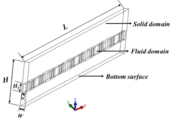
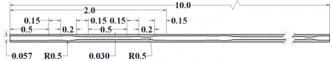
In the present study, 10 microchannels were arranged in a substrate with the bottom size of 10 mm x 1 mm (L x W) and height (H) of 0.9 mm. Due to symmetry conditions, only one unit of microchannel was considered as a computational model. There were five repetitive sections each of 2 mm length along the flow direction. The fluid domain width (Wf), depth (Hf), substrate thickness, cover plate thickness and wall thickness were 0.057 mm, 0.18 mm, 0.27 mm, 0.45 mm and 0.0215 mm respectively. A schematic of the microchannel with periodically convergent-divergent shape consisting of ribs and cavities along the flow direction is shown in Fig. 1.
Figure 1. Unit cell of convergent-divergent microchannel with ribs and cavities.
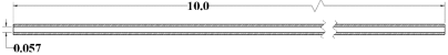
A rectangular microchannel with the same geometry as considered by Kawano et al. [38] used in their experimental investigation was taken as the reference microchannel to evaluate improvement in thermal performance. The following four configurations were considered to investigate the effect of channel shape with and without ribs and cavities (Fig. 2).
· Case 1. Rectangular microchannel
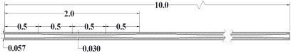
· Case 2. Rectangular microchannel with ribs and cavities
· Case 3. Convergent-divergent microchannel (CD)
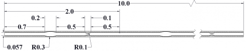
· Case 4. Convergent-divergent microchannel with ribs and cavities (CD-RC)
(a)
(b)
(c)
(d)
Figure 2. Microchannel unit cell with different geometries (a) rectangular, (b) rectangular with ribs and cavities, (c) convergent-divergent and (d) convergent-divergent with ribs and cavities.
2.2 Governing equations
The following assumptions were used to simplify the flow and heat transfer analysis.
· Steady, three-dimensional fluid flow and heat transfer.
· Laminar, newtonian and incompressible fluid flow.
· Negligible radiation and gravitational effects.
The governing equations for 3D, steady behavior may be written as
Continuity equation:
$\frac{\partial}{\partial x_{i}}\left(\rho u_{i}\right)=0$ (1)
Momentum equation:
$\frac{\partial}{\partial x_{i}}\left(\rho_{f} u_{i} u_{j}\right)=-\frac{\partial p}{\partial x_{j}}+\frac{\partial}{\partial x_{i}}\left[\mu_{f}\left(\frac{\partial u_{j}}{\partial x_{i}}+\frac{\partial u_{i}}{\partial x_{j}}\right)\right]$ (2)
Energy equation:
$\frac{\partial\left(\rho_{f} u_{i} c_{p f} T\right)}{\partial x_{i}}=\frac{\partial}{\partial x_{i}}\left(k_{f} \frac{\partial T}{\partial x_{i}}\right)+\emptyset$ (3)
$\emptyset=\mu_{f}\left[2\left(\frac{\partial u_{i}}{\partial x_{i}}\right)^{2}+\left(\frac{\partial u_{j}}{\partial x_{i}}+\frac{\partial u_{i}}{\partial x_{j}}\right)^{2}\right]$ (4)
The energy equation for solid is written as
$\frac{\partial}{\partial x_{i}}\left(k_{S} \frac{\partial T}{\partial x_{i}}\right)=0$ (5)
where ρ denotes the density, µ the dynamic viscosity, cp the specific heat capacity and k the thermal conductivity. Here subscripts f and s refer to fluid and solid, respectively.
2.3 Boundary conditions
Water was used as the working fluid in microchannel with uniform velocity. The inlet temperature of water was taken as 293 K. The inlet velocity of fluid was taken according to the value of Re (ranging from 120 - 900), hydraulic diameter and fluid properties. Silicon was taken as the material of the heat sink. A constant heat flux of 90 W/cm2 was supplied on the bottom surface to simulate typical heat generation from an electronic chip. Other walls were kept insulated. In addition, the top surface of silicon substrate was assumed to be adiabatic. The centre plane of the solid fin was taken as the plane of symmetry. Moreover, at the remaining walls interaction between solid conduction and fluid convection was considered. The atmospheric pressure condition was used at the outlet. No slip conditions were used at the interface of the solid-fluid parts.
$T_{s}=T_{f}$ (6)
$-k_{s}\left[\frac{\partial T_{s}}{\partial n}\right]_{w}=-k_{f}\left[\frac{\partial T_{f}}{\partial n}\right]_{w}$ (7)
The center plane of the solid fin was set as the plane of symmetry:
$\frac{\partial}{\partial n}=0$ (8)
Other walls were treated as adiabatic:
$\left[\frac{\partial T}{\partial n}\right]_{w}=0$ (9)
By computationally solving the equations (1 – 9) along with the boundary conditions, velocity, pressure and temperature fields were determined. Thereafter heat transfer coefficient, pressure drop, friction factor and surface temperature were obtained.
2.3 Solution method
The simulations were performed using CFD solver ANSYS FLUENT 15.0. The SIMPLE algorithm was used to deal with pressure-velocity coupling. The second-order upwind scheme was used to discretize the convective terms. The solution was assumed to be converged when the values of the scaled residuals for continuity, momentum and energy equations were less than 10-6, 10-6 and 10-9 respectively. To validate the code, the present predictions were compared with the experimental results of Kawano et al. [38] and a good agreement between the two for thermal resistance was obtained (Fig. 3). The thermal resistance (R) of the microchannel was defined as the ratio of difference between the heated surface (Tmax) and inlet (Tin) temperatures to heat flux (q) supplied at the bottom surface.
$R=\frac{T_{\max }-T_{i n}}{q}$ (10)
Figure 3. Code validation with reported experimental results.
2.4 Grid independence study
A grid sensitivity study was performed for all the microchannels considered. Four unstructured grids with different sizes of 0.145 million (coarse), 0.214 million (fine), 0.254 million (very fine) and 0.302 million (ultra-fine) were used for Case 1. A refinement of mesh was carried out in all the three directions to accurately resolve solid-fluid interface region. The inlet velocity was specified as 1.312 m/s corresponding to Re of 144. The pressure drop along the channel length was observed to determine the grid independent solution. It was observed that deviations of the pressure drop using 0.145, 0.172, 0.214, 0.254 million grids from that of 0.302 million grids were 4.35%, 2.04%, 0.95% and 0.03%. Therefore, the mesh with 0.254 million grids was found to be sufficient for the present study. Grid independence was similarly established for the grids selected for the other cases.
2.5 Parameters considered
The following parameters were considered in order to calculate the overall thermal performance of microchannel. Reynolds number Re is defined as
$R e=\frac{\rho_{f} u_{i n} D_{h}}{\mu_{f}}$ (11)
where, ρf denotes the fluid density, uin the inlet fluid velocity, Dh the hydraulic diameter and µf the mass-averaged fluid dynamic viscosity. The hydraulic diameter was defined as $D_{h}=\frac{2 W_{f} H_{f}}{w_{f}+H_{f}}$ with the width Wf and height Hf of the constant cross-section segment.
The average fanning friction factor (f) was computed by the pressure drop (Δp) across the length of the microchannel (L) and expressed as
$\overline{f}=\frac{\Delta p D_{h}}{2 \rho_{f} L u_{i n}^{2}}$ (12)
The average heat transfer coefficient $\overline{h}$ and average Nusselt number $\overline{N u}$ were computed by the expressions
$\overline{h}=\frac{q \cdot A_{b}}{n A_{c o n t}\left(\overline{T_{w}}-\overline{T_{f}}\right)}$ (13)
$\overline{N u}=\frac{\overline{h} D_{h}}{k_{f}}$ (14)
where, q denotes the heat flux from electronic components, Ab the bottom surface area, Acont the inner wall/fluid contact area, n the number of microchannels, kf the thermal conductivity of fluid, $\overline{T_{w}}$ the average temperature of the channel wall surface and $\overline{T_{f}}$ the mean bulk fluid temperature between the inlet and outlet.
The pumping power is given by the expression
$P=n u_{i n} A_{6} \Delta p$ (15)
where, n denotes the total number of microchannel, Ac the inlet cross-sectional area per channel.
In this section we present flow structure, pressure drop and heat transfer characteristics due to convergent-divergent shape with ribs and cavities. The present simulated results were found to be in excellent agreement with the reported results in the literature for developing flow by Dewan and Kamal [39].
3.1 Flow structure
In a typical rectangular microchannel heat transfer performance deteriorates along the flow direction due to parallel streamlines and a thick boundary-layer. Here we have analysed the heat transfer augmentation by deflecting the streamlines and causing interruption of boundary-layer by using convergent-divergent shape with ribs and cavities. When liquid flows through a convergent-divergent (CD) shape, velocity increases in the convergent portion and it is redirected towards the constant cross-section segment followed by the divergent segment where velocity decreases due to a sudden expansion of area. Vortices are formed in the divergent segment and their intensity depends significantly on Re and divergence angle. When ribs and cavities are incorporated, streamlines deflect to cavity at the entrance of the expansion region causing vortex generation. Here velocity becomes quite low and a laminar stagnation zone appears. Fluid is again accelerated when it passes over the ribs and the maximum velocity occurs in this region followed by small recirculation zone downstream of the ribs. A combined effect of cavities and ribs produces a periodic interruption of hydrodynamic and thermal boundary-layers lead to enhanced fluid mixing.
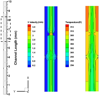
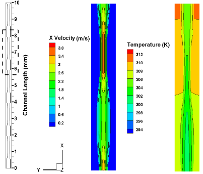
Fig. 4 shows velocity and temperature contours for the microchannel in the x-y plane located at the middle of the fluid domain depth (z = 0.36 mm) at Re = 144. Fig. 4 (a) shows that in the rectangular microchannel, the maximum velocity occurs at the channel center and streamlines are parallel while in the case of the rectangular microchannel with ribs and cavities [Fig. 4 (b)], the flow stream deflects towards cavities and velocity becomes relatively low causing a recirculation zone. The velocity increases at the location of rib due to blocking effect. A periodic interruption of hydrodynamic boundary-layer can be observed due to ribs and cavities which results a small variation in the normal velocity while in the case of the rectangular channel, variation in the normal velocity is quite high due to a streamlined flow. As a result, mixing of cold fluid from channel center and hot fluid from the vicinity of walls is possible. Such repeated change in flow and mixing of fluid by interruption effectively improves the thermal performance of a microchannel.
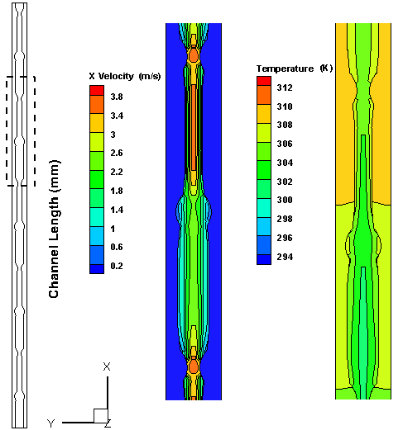
In the case of CD microchannel [Fig. 4 (c)], fluid velocity increases in the convergent segment and reaches its maximum value at the constant cross-section segment and thereafter it decreases through the divergent length. Due to the placement of cavities in the converging segment and ribs in divergent segment in the case of CD-RC microchannel [Fig. 4 (d)], the streamlines deflect to cavity and recirculation zone appears while ribs disturb the flow in the divergent segment. In the recirculated zone of cavity, flow velocity is minimum. Therefore, the smallest variation in the normal velocity is observed in the case of CD-RC microchannel. This behavior suggests that the converging-diverging geometry along with ribs and cavities result in interruption and restart of boundary-layer leading to a developing flow in the microchannel. The corresponding thermal characteristics of all the above-mentioned microchannels are discussed in Section 3.4. The interruption of streamlines depends on the expansion constriction ratio, while the size of the recirculation zone depends on geometry of ribs and cavities and fluid velocity (eventually Re).
(a)
(b)
(c)
(d)
Figure 4. Temperature and velocity contours along the flow direction in microchannel at Re = 144 (a) rectangular, (b) rectangular with ribs and cavities, (c) convergent-divergent and (d) convergent-divergent with ribs and cavities.
3.2 Pressure drop
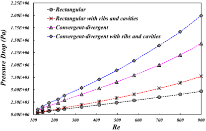
Fig. 5 (a) represents the corresponding pressure drop along the channel length at Re = 144. For the rectangular microchannel, the pressure decreases linearly along the flow direction. For CD microchannel the pressure loss is more in the diverging segment than that at other segments. This pressure drop is not only due to friction loss along the flow direction but also due to obstacles in fluid flow. It is clear that the effect of convergent-divergent shape is more dominant than ribs and cavities on pressure drop. Furthermore, pressure drop for all three geometries is higher than that for the rectangular microchannel. The CD-RC microchannel has the highest pressure drop followed by the CD shape and rectangular shape with ribs and cavities, respectively. This behavior is mainly due to changes in flow passage configurations. These geometrical changes cause flow disruption, blocking effect and recirculation flow around bend corners and in cavities, thereby resulting in a larger pressure drop. Generally, heat transfer rate increases with an increase in flow rate. However, a higher-pressure drop is encountered with an increase in volumetric flow rate as well. The effects of Re on the pressure drop are presented in Fig. 5 (b) and it can be observed that the pressure drop increases linearly with Re for all cases considered. The increase become significant at high Reynolds number. The rate of pressure drop for CD-RC microchannel is the highest compared to that for other cases. Thus CD-RC microchannel loses its effectiveness in thermal performance improvement at high Re.
3.3 Friction factor
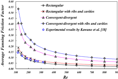
The frictional losses arise mainly due to flow losses resulting from periodic expansion - contraction, recirculation in cavities and flow blockages between ribs. A variation of the friction factor with Re for various channel configurations is shown in Fig. 6. Friction factor is observed to be high due to change in shape and presence of ribs and cavities. Fig. 6 shows that the friction factor decreases with Re for all channel shapes. There is a good agreement between the reported experimental results by Kawano et al. [38] and the present simulated results for rectangular microchannel (Fig. 6). It is also observed that the CD-RC microchannel has the highest friction factor coefficient compared to that of the other microchannels.
(a)
(b)
Figure 5. (a) Pressure drop along the channel length for Re = 144 and (b) pressure drop variation with Re.
Figure 6. Average fanning friction factor variation with Re.
3.4 Heat transfer characteristics
Change in shape and obstacles have a strong effect on heat transfer characteristics due to interruption and restart of boundary-layer. In the case of rectangular microchannel, heat transfer from the substrate to the flowing fluid is quite poor due to thickening of thermal boundary-layer. Fig. 4 shows temperature distribution for the microchannel in the x-y plane located at the middle of the fluid domain depth (z = 0.36 mm) at Re = 144. It can be observed in Fig. 4 (a) that variation of temperature in the normal direction is higher than that of other channels due to poor mixing of cold and hot fluids. For the CD microchannel, the temperature of the divergent segment is somewhat higher than that of the convergent segment and the maximum temperature occurs at the inlet of the convergent segment [Fig. 4 (c)]. This behavior is due to accelerated and decelerated flow in different segments. It can also be observed that the lowest temperature occurs at the center of the channel as in the case of the rectangular microchannel but the temperature difference near the wall and core flow regions is less than that of the rectangular case.
The cavities and ribs inside the microchannel have a significant effect on its thermal performance [Figs. 4 (b) and 4 (d)]. Thermal boundary-layers are broken up periodically and restarted due to obstruction by ribs. Vortices are also formed downstream of the ribs and these disturb the flow field. As already discussed in Section 3.1, flow velocities are relatively low at locations of cavities due to formation of laminar stagnation zone and these increase at the locations of ribs due to blocking effect. Furthermore, the cavities produce radial pressure gradient, which further enhances the flow mixing and provide a good convection heat transfer. Combined effects of interruption, restart of boundary layer, recirculation and enhanced fluid mixing lead to a significant heat transfer in the CD-RC microchannel.
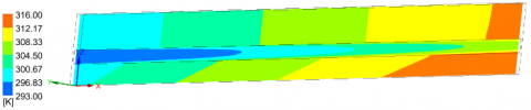
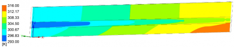
In order to further understand the local heat transfer enhancement, Fig. 7 shows temperature distributions for microchannels in the x-z plane located at the middle of fluid domain (y = 0.050 mm) for Re = 144. It can be observed from Fig. 7 (a) that the temperature of the fluid in the core flow of the rectangular microchannel is the highest due to a streamlined flow. As the boundary-layer is interrupted and restarted, mixing of hot fluid near the wall with cold fluid in the core region takes place leading to lowering the temperature of fluid flowing in the channel [Figs. 7 (b) and (c)]. The CD-RC microchannel has better thermal performance than other microchannels considered [Fig. 7 (d)].
The mechanism of heat transfer enhancement in the present CD-RC microchannel can be described as follows: (1) Heat transfer area is increased due to the presence of cavities and ribs but the frictional area is also increased resulting in a simultaneous high pressure drop; (2) Jetting and throttling effects are caused by the periodic converging-diverging shape; (3) Laminar stagnation zones appear at cavities for low values of Re but the presence of ribs weakens their formation and effectively intensifies the effect of disturbance. For high values of Re, the recirculation produced in the cavities and downstream of the ribs leads to a good mixing of cold and hot fluids; and (4) the most significant heat transfer characteristics is thinning of thermal boundary-layers due to interruptions by ribs and cavities.
(a)
(b)
(c)
(d)
Figure 7. Temperature contours along the flow direction in channel at Re = 144 (a) rectangular, (b) rectangular with ribs and cavities, (c) convergent-divergent and (d) convergent-divergent with ribs and cavities.
Fig. 8 shows the average Nusselt number( $\overline{N u}$ ) variation with Re. It can be observed that, the value of $\overline{N u}$ increases with Re for all cases. The average Nusselt number in the CD-RC microchannel is the highest in all the cases and there is an increase of 15% to 46% compared to the rectangular shape over the range of Re considered. The higher $\overline{N u}$ for the CD-RC microchannel shows that ribs and cavities can give rise to significant heat transfer enhancement. It can also be observed that $\overline{N u}$ for the CD-RC microchannel rises rapidly at smaller Re and the rate of increase slows down with an increase in Re. This behavior shows that the effectiveness of the CD-RC microchannel gradually decreases with an increase of Re.
Figure 8. Average Nusselt number variation with Re.
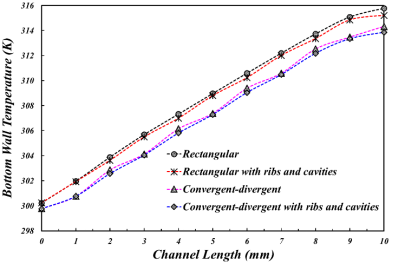
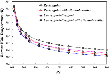
The bottom surface temperature and its uniformity are quite important in a microchannel as these are directly related to mean time failure and performance of the electronic devices. Fig. 9 (a) shows the bottom surface temperature along the channel length at Re = 144. It can be observed that the rectangular shaped channel has the highest bottom surface temperature followed by the rectangular shape with ribs and cavities and the performance of the CD-RC microchannel is the best among all the geometries considered. An increase in temperature due CD shape is countered by ribs and cavities thus resulting in a uniform temperature distribution throughout the length in the case of the CD-RC microchannel. Fig. 9 (b) shows a variation of the average temperature of the heated surface with Re. The slopes of the average bottom surface temperature curve decrease with Re for all cases. Here temperature decreases rapidly for low Re up to Re = 300. As Re is increased, the CD shape has less heat transfer than that of rectangular shape with ribs and cavities. This behavior is because ribs and cavities continuously interrupt boundary-layer while in the CD shape fluid mixing is small at high values of Re. This means it is not an efficient method to lower the bottom surface temperature of heat sink by increasing the flow rate when Re exceeds a certain value.
(a)
(b)
Figure 9. (a) Bottom wall temperature along the length at Re = 144 and (b) bottom wall temperature variation with Re.
To determine the overall thermal performance of microchannel, thermal resistance and pumping power were computed and analysed. A variation in overall thermal resistance with Re is shown in Fig. 10. It can be observed that the overall thermal resistance decreases with Re in all cases. It can also be seen that the overall thermal resistance of the rectangular microchannel is higher than that of the CD microchannel for the same flow rate due to poor fluid mixing. Moreover, the CD-RC microchannel provides overall the lowest thermal resistance than by the other microchannels due to separation of mainstream, strong mixing of fluid and interruption of boundary-layer. A good agreement is also observed for thermal resistance for rectangular microchannel between the present simulation results and experimental results by Kawano et al. [38]. Since thermal resistance indirectly represents the maximum bottom surface temperature, the use of CD-RC microchannel provides an efficient method to lower the maximum temperature of the bottom surface of substrate where electronic chip is mounted. However, with an increase in Re, the rate of decrease of overall thermal resistance reduces and hence its effectiveness is gradually lost at higher values of Re. Pumping power or pressure drop is another factor to consider its overall thermal performance for practical situations.
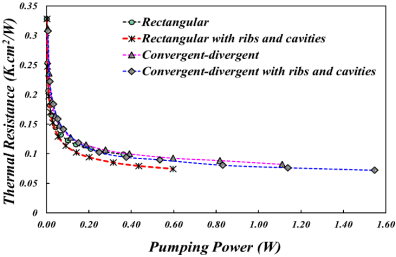
A variation in thermal resistance with pumping power at the corresponding volumetric flow rate is presented in Fig. 11. It shows that the thermal resistance decreases continuously with increasing pumping power for all cases but its effectiveness diminishes at higher values of Re. It is also observed from Fig. 11 that the CD shape is more susceptible to pressure drop penalty than ribs and cavities. Therefore for the same pumping power, the rectangular shape with ribs and cavities has the least thermal resistance in all cases.
Figure 10. Thermal resistance variation with Re
Figure 11. Thermal resistance variation with pumping power
In practical applications, such as, electronic chip cooling, the heat load is applied at a certain finite distance from the fluid-solid interface, which leads to multi-dimensional conjugate heat transfer. For such applications, the maximum temperature is a critical issue for failure of heat sink. Therefore the thermal resistance is a reasonable factor to represent thermal performance of a microchannel. Three-dimensional simulations of fluid flow and heat transfer in microchannel with different geometries have been performed under a constant heat flux condition at the bottom surface of substrate. The effect of volumetric flow rate on pressure drop, flow field and temperature distribution is studied to evaluate its thermal performance. It is shown that the use of convergent-divergent shape with ribs and cavities can reduce the overall thermal resistance by approximately 40% and can make temperature of heated surface quite uniform. This heat transfer enhancement is due to combined effect of convergent-divergent shape with ribs and cavities. Interruption and restart of hydraulic and thermal boundary-layers takes place along with enhanced fluid mixing due to formation of vortices in cavities. To further improve the thermal performance an appropriate value of Re can enhance the intensity of vortex and reduce the thickness of thermal boundary-layer. The results show that increasing Re leads to an enhanced heat transfer in terms of increased averaged Nusselt number from 15% to 46%. The combined effect of convergent and divergent shape with ribs and cavities is effective in heat transfer augmentation but it loses gradually its effectiveness at high values of Re due to a large pressure drop penalty.
|
L |
Microchannel length (mm) |
|
W |
Microcahnnel width (mm) |
|
H |
Microchannel height (mm) |
|
Dh |
Hydraulic diameter (mm) |
|
Cp |
Specific heat (J/kgK) |
|
g |
Gravitational acceleration (m/s2) |
|
k |
Thermal conductivity (W/mK) |
|
T |
Temperature (K) |
|
f |
Friction factor |
|
u |
Velocity (m/s) |
|
p |
Pressure (Pa) |
|
V |
Volumetric flow rate (m3/s) |
|
P |
Pumping power (W) |
|
h |
Heat transfer coefficient (W/m2K) |
|
Greek Symbols |
|
|
ρ |
Density (kg/m3) |
|
µ |
Dynamic viscosity (Ns/m2) |
|
Δ |
Gradient |
|
Subscripts |
|
|
w |
Wall |
|
in |
Inlet |
|
s |
Solid |
|
f |
Fluid |
[1] Tuckerman D.B., Pease R.F.W. (1981). High-performance heat sinking for VLSI, IEEE Electron Device Lett., Vol. EDL-2, No. 5, pp. 126-129. DOI: 10.1109/EDL.1981.25367
[2] Wang B.X., Peng X.F. (1994). Experimental investigation on liquid forced convection heat transfer through microchannels, International Journal of Heat and Mass Transfer, Vol. 37, pp. 73-82. DOI: 10.1016/0017-9310 (94) 90011-6
[3] Peng X.F., Peterson G.P. (1996). Convective heat transfer and flow friction for water flow in microchannel structures, International Journal of Heat and Mass Transfer, Vol. 39, No. 12, pp. 2599-2608. DOI: 10.1016/0017-9310 (95) 00327-4
[4] Qu W., Mudawar I. (2002). Analysis of three dimensional heat transfer in micro-channel heat sinks, International Journal of Heat and Mass Transfer, Vol. 45, pp. 3973-3985. DOI: 10.1016/S0017-9310 (02) 00101-1
[5] Rostami A., Saniei N., Mujumdar A.S. (2000). Liquid flow and heat transfer in microchannel: A review, International Journal of Heat and Technology, Vol. 18, No. 2, pp. 59-68. DOI: 10.18280/ijht/180208
[6] Steinke M.E., Kandlikar S.G. (2006). Single phase liquid friction factors in microchannels, International Journal of Thermal Sciences, Vol. 45, pp. 1073-1083. DOI: 10.1016/j.ijthermalsci.2006.01.016
[7] Steinke M.E., Kandlikar S.G. (2004). Review of heat transfer enhancement techniques for application in micro-channels, mini-channels and micro-devices, International Journal of Heat and Technology, Vol. 22, No. 2, pp. 3-11. DOI: 10.18280/ijht.220201
[8] Rosaguti N.R., Fletcher D.F., Haynes B.S. (2006). Laminar flow and heat transfer in periodic serpentine channel with semi-circular cross-section, International Journal of Heat and Mass Transfer, Vol. 49, pp. 2912-2923. DOI: 10.1016/j.ijheatmasstransfer.2006.02.015
[9] Rosaguti N.R., Fletcher D.F., Haynes B.S. (2007). Low Reynolds number heat transfer enhancement in sinusoidal channels, Chemical Engineering Science, Vol. 62, pp. 694-702. DOI: 10.1016/j.ces.2006.09.045
[10] Dewan A. (2011). Tackling Turbulent Flow in Engineering, Springer, Berlin, Heidelberg, Germany. DOI: 10.1007/978-3-642-14767-8
[11] Adewumi O.O., Bello-Ochende T., Meyer J.P. (2016). Constructal design of single microchannel heat sink with varying length and temperature-dependent fluid properties, International Journal of Heat and Technology, Vol. 34, Special issue 1, pp. S167-S172. DOI: 10.18280/ijht.34S122
[12] Conti A., Lorenzini G., Jaluiria Y. (2012). Transient conjugate heat transfer in straight microchannel, International Journal of Heat and Mass Transfer, Vol. 55, 25-26, pp. 7532-7543. DOI: 10.1016/j.ijheatmasstransfer.2012.07.046
[13] Salman B.H., Mohammed H.A., Kherbee A. Sh., Ahmed H.E. (2015). The effect of geometrical parameter on enhancing the heat transfer inside a microtube, International Journal of Heat and Technology, Vol. 33, No. 3, pp. 79-84. DOI: 10.18280/ijht.330311
[14] Sui Y., Teo C.J., Lee P.S., Chew Y.T., Shu C. (2010). Fluid flow and heat transfer in wavy microchannels, International Journal of Heat and Mass Transfer, Vol. 53, pp. 2760-2772. DOI: 10.1016/j.ijheatmasstransfer.2010.02.022
[15] Amanifard N., Haghi A.K. (2007). Numerical analysis of fluid flow and heat transfer in microchannels, International Journal of Heat and Technology, Vol. 25, No. 1, pp. 103-110. DOI: 10.18280/ijht.250114
[16] Mohammed H.A., Gunnasegaran P., Shuaib N.H. (2011). Influence of channel shape on the thermal and hydraulic performance of microchannel heat sink, International Communications in Heat and Mass Transfer, Vol. 38, pp. 474-480. DOI: 10.1016/j.icheatmasstransfer.2010.12.031
[17] Alfaryjat A.A., Mohammed H.A., Adam N.M., Ariffin M.K.A., Najafabadi M.I. (2014). Influence of geometrical parameters of hexagonal, circular and rhombus microchannel heat sinks on the thermo-hydraulic characteristics, International Communications in Heat and Mass Transfer, Vol. 52, pp. 121-131. DOI: 10.1016/j.icheatmasstransfer.2014.01.015
[18] Chai L., Xia G., Wang L., Zhou M., Cui Z. (2013). Heat transfer enhancement in microchannel heat sinks with periodic expansion-constriction cross-sections, International Journal of Heat and Mass Transfer, Vol. 62, pp. 741-751 DOI: 10.1016/j.ijheatmasstransfer.2013.03.045
[19] Sheikhalipour T., Abbassi A. (2010). Numerical analysis of viscous dissipation effect in trapezoidal micro-channels, International journal of Heat and Technology, Vol. 28, No. 1, pp. 61-66. DOI: 10.18280/ijht.280109
[20] Dehgan M., Daneshipour M., Valipour M.S., Rafee R., Saedodin S. (2015) Enhancing heat transfer in microchannel heat sinks using converging flow passages, Energy Conversion and Management, Vol. 92, pp. 244-250. DOI: 10.1016/j.enconman.2014.12.063
[21] Duryodhan V.S., Singh A., Singh S.G., Agrawal A. (2015). Convective heat transfer in diverging and converging microchannels, International Journal of Heat and Mass Transfer, Vol. 80, pp. 424-438. DOI: 10.1016/j.ijheatmasstransfer.2014.09.042
[22] Foong A.J.L., Ramesh N., Chandratilleke T.T. (2009). Laminar convective heat transfer in a microchannel with internal longitudinal fins, International Journal of Thermal Sciences, Vol. 48, pp. 1908-1913. DOI: 10.1016/j.ijthermalsci.2009.02.015
[23] Hong F., Cheng P. (2009). Three dimensional numerical analyses and optimization of offset strip-fin microchannel heat sinks, International Communications in Heat and Mass Transfer, Vol. 36, pp. 651-656. DOI: 10.1016/j.icheatmasstransfer.2009.02.015
[24] Lee Y.J., Lee P.S., Chou S.K. (2013). Numerical study of fluid flow and heat transfer in the enhanced microchannel with oblique fins, ASME Journal of Heat Transfer, Vol. 135, 041901, pp. 1-10. DOI: 10.1115/1.4023029
[25] Lee Y.J., Singh P.K., Lee P.S. (2015). Fluid flow and heat transfer investigations on enhanced microchannel heat sink using oblique fins with parametric study, International Journal of Heat and Mass Transfer, Vol. 81, pp. 325-336. DOI: 10.1016/j.ijheatmasstransfer. 2014.10.018
[26] Dewan A., Srivastava P. (2015). A review of heat transfer enhancement through flow disruption in a microchannel, Journal of Thermal Science, Vol. 24, No. 3, pp. 203–214. DOI: 10.1007/s 11630-015-0775-1
[27] Shukla A.K., Dewan A. (2017). Flow and thermal characteristics of jet impingement: comprehensive review, International Journal of Heat and Technology, Vol. 35, No. 1, pp. 153-166. DOI: 10.18280/ijht.350121
[28] Wei X.J., Joshi Y.K., Ligrani P.M. (2007). Numerical simulation of laminar flow and heat transfer inside a microchannel with one dimpled surface, ASME Journal of Electronic Packaging, Vol. 129, pp. 63-70. DOI: 10.1115/1.2429711
[29] Gururatana S. (2012). Numerical simulation of micro-channel heat sink with dimpled surfaces, American Journal of Applied Sciences, Vol. 9, No. 3, pp. 399-404. DOI: 10.3844/ajassp.2012.399.404
[30] Liu Y., Cui J., Li W., Zhang N. (2011). Effect of surface microstructure on microchannel heat transfer performance, ASME Journal of Heat Transfer, Vol. 133/124501, pp. 1-6. DOI: 10.1115/1.4004594
[31] Xie Y., Shen Z., Zhang D., Lan J. (2014). Thermal performance of a water-cooled microchannel heat sink with grooves and obstacles, ASME Journal of Electronic Packaging, Vol. 136/021001, pp. 1-8. DOI: 10.1115/1.4025757
[32] Xia G., Chai L., Zhou M., Wang H. (2011). Effects of structural parameters on fluid flow and heat transfer in a microchannel with aligned fan-shaped reentrant cavities, International Journal of Thermal Sciences, Vol. 50, pp. 411-419. DOI: 10.1016/j.ijthermalsci.2010.08.009
[33] Xia G., Chai L., Wang H., Zhou M., Cui Z. (2011). Optimum thermal design of microchannel heat sink with triangular re-entrant cavities, Applied Thermal Engineering, Vol. 31, pp. 1208-1219. DOI: 10.1016/j.applthermaleng.2010.12.022
[34] Chai L., Xia G., Wang H.S. (2016). Parametric study on thermal and hydraulic characteristics of laminar flow in microchannel heat sink with fan-shaped ribs on side walls, International Journal of Heat and Mass Transfer, Vol. 97, pp. 1069-1080. DOI: 10.1016/j.ijheatmasstransfer.2016.02.077
[35] Chai L., Xia G., Wang H.S. (2016). Numerical study of laminar flow and heat transfer in microchannel heat sink with offset ribs on sidewalls, Applied Thermal Engineering, Vol. 92, pp. 32-41. DOI: 10.1016/j.applthermaleng.2015.09.071
[36] Xia G., Zhai Y., Cui Z. (2013). Numerical investigation of thermal enhancement in a micro heat sink with fan-shaped reentrant cavities and internal ribs, Applied Thermal Engineering, Vol. 58, pp. 52-60. DOI: 10.1016/j.applthermaleng.2013.04.005
[37] Li Y.F., Xia G., Ma D.D., Jia Y.T., Wang J. (2016). Characteristics of laminar flow and heat transfer in microchannel heat sinks with triangular cavities and rectangular ribs, International Journal of Heat and Mass Transfer, Vol. 98, pp. 17-28. DOI: 10.1016/j.ijheatmasstransfer.2016.03.022
[38] Kawano M.I.K., Minakami K., Iwasaki H. (2001). Development of microchannels heat exchanging, JSME International Journal, Series-B, Vol. 44, No. 4, pp. 592–598. DOI: 10.1299/jsmeb.44.592
[39] Dewan A., Kamal H. (2017). Analysis of interrupted rectangualr microchannel heat sink with high aspect ratio, Journal of Applied Fluid Mechanics, Vol. 10, pp. 117-126. DOI: 10.18869/acadpub.jafm.73.238.26366