OPEN ACCESS
This paper aims to reveal the atomization features of nozzles for humidification chambers. Targeted at three commonly used nozzles (TF6, TF8 and AM4), the author investigated into the effect of nozzle backpressure on droplet size, and examined the diameters and distribution spans of the droplets at different distances to the nozzle. The results show that the droplet diameters decreased with the increase in spray pressure. However, there was a critical value of the pressure. The location of secondary atomization was determined by analysing the atomization features at different locations below the nozzle. It is concluded that the location is 7cm below the nozzle for TF6 nozzle, 12cm below the nozzle for TF8 nozzle, and 10cm below the nozzle for AM4 nozzle. Moreover, the least square method was used to fit an empirical correlation for the droplets atomized by the nozzle in the secondary atomization area. The empirical correlation was then converted to a functional relation of the Weber number and Reynolds number. The research findings make it possible to predict the particle diameters from the nozzle exit.
humidification chamber, atomization features, critical pressure, secondary atomization
The key to the humidification and heat exchange in a humidification chamber lies in the good contact between the air and droplets. To maintain a desirable air-droplet contact, it is necessary to identify the spray atomization features of nozzles. In practice, the quality of atomization is often evaluated by the easy-to-obtain mean diameter of atomized droplets instead of the droplet size distribution, which involves various factors such as the number, masses and volumes of various droplets.
The droplet size distribution can be described by both empirical functions and theoretical formulas. The empirical functions are derived from extensive experiments, namely the Nukiyama-Tanasawa distribution function, Rosin-Rammler distribution function and its corrected form, as well as the upper limit normal distribution. The typical theoretical formulas include the normal distribution, logarithmic normal distribution, maximum entropy distribution [1] etc. [2-11]
The representative studies on spray atomization features of nozzles are as follows. Targeted at fuel atomizer nozzles, Lefebvre [12] summed up the nozzle flow, atomization, external flow and droplet distribution of many kinds of nozzles, including but not limited to flat orifice nozzles, vortex nozzles, rotating nozzles and air-assisted nozzles, and detailed the applicable ranges of various empirical formulas on droplet diameters. Bayvel [13] introduced the types and applications of atomizer nozzles and presented several empirical formulas on droplet diameters atomized by some nozzle types. Liu et al. [14] investigated the flow and atomization features of bubble atomizer nozzles through experiments, and obtained the change patterns in the atomized droplet diameter with the spray pressure and liquid-to-gas ratio. Through dimensional analysis, Liu et al. depicted the droplets atomized by bubble atomizer nozzles by Sauter mean diameter formula, with such variables as Weber number, Reynolds number and liquid-to-gas ratio. Chen et al. [15] disclosed the effect of gas-liquid two-phase pressure on the dimensions of droplets atomized by two-phase nozzles and the flow of these nozzles, studied the features of single-phase nozzles through experiments, and compared the features of single-phase nozzles with the those of two-phase nozzles. Liu et al. [16] performed experiments to acquire the empirical relationship for droplets atomized by low-pressure airblast nozzles. Zhang et al. [17] experimentally studied the change patterns in the Sauter mean diameter, flux and mean velocity of droplets atomized by double-orifice centrifugal nozzles. Liao et al. [18, 19] theorized the basic equations of fluid motion and pressure distribution in centrifugal nozzles.
The above studies mainly focus on fuel atomization in the aerospace field. The atomization nozzle, medium and environment in these studies are a far cry from those in humidification chambers. Of course, the methods and empirical formulas can be referred to in our research [20-23].
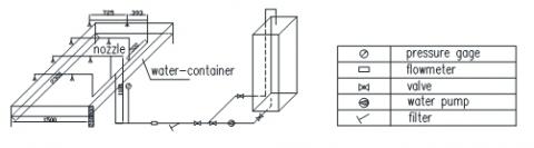
Figure 1 shows the experimental system for the atomization features of a nozzle. The system consists of a water tank, a high-pressure water pump, control valves, a filter, a measurement section (a Spraytec spray particle size analyser, a flow meter, a pressure gauge and a thermometer), a nozzle and a water pan.
Figure 1. The experimental system
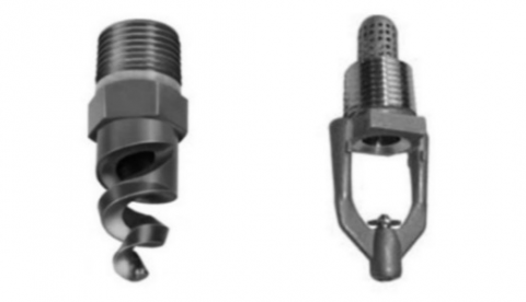
The target nozzles include the TF6 nozzle (pressure-type spiral nozzle), TF8 nozzle (pressure-type spiral nozzle) and the AM4 nozzle (impinging-type atomizer nozzle) (Figure 2). The experimental conditions are listed in Table 1, and the main measuring parameters and instruments are displayed in Table 2.
Pressure-type spiral nozzle TF6/TF8 Impinging-type atomizer nozzle AM4
Figure 2. The nozzle structures
Table 1. Experimental conditions
|
No. |
Name of experiment |
Experimental conditions |
Distance between the nozzle and emitting end (cm) |
Distance between the nozzle and receiving end (cm) |
Vertical distance between the nozzle and laser (cm) |
|
1 |
Experiment on the atomization characteristics of the nozzle |
TF6_3cm |
44 |
43 |
3 |
|
2 |
Name of experiment |
TF6_7cm |
42 |
45 |
7 |
|
3 |
Experiment on the atomization characteristics of the nozzle |
TF6_12cm |
43 |
44 |
12 |
|
4 |
Name of experiment |
TF8_7cm |
42 |
45 |
7 |
|
5 |
Experiment on the atomization characteristics of the nozzle |
TF8_12cm |
43 |
44 |
12 |
|
6 |
Name of experiment |
TF8_15cm |
46 |
41 |
15 |
|
7 |
Experiment on the atomization characteristics of the nozzle |
AM4_5cm |
132 |
108 |
5 |
|
8 |
Name of experiment |
AM4_10cm |
132 |
108 |
10 |
|
9 |
Experiment on the atomization characteristics of the nozzle |
AM4_16cm |
132 |
108 |
16 |
Table 2. Main experimental parameters and instrument
|
System |
Measurement parameters |
Instrument |
Measuring range |
|
Spray system |
Spray water temperature |
Thermometer |
0~50℃ |
|
Spray water flow |
Turbine flow meter LWGY-25 and digit expression meter |
0~10 m3/h |
|
|
Spray system pressure |
Pressure meter YB150 |
2.5 MPa, accuracy 0.4 |
|
|
Droplet diameter |
Malvern spraytec particle size analyzer |
0.1 μm~2000 μm |
3.1 Influencing factors
Based on the atomization mechanism, the influencing factors of atomized droplet size distribution were determined as the nozzle diameter, spray pressure, air density, as well as the surface tension coefficient, dynamic viscosity coefficient and density of the liquid [19]. Since the in-nozzle liquid velocity changes with the pressure, the indeterminate function can be expressed with the diameter of the atomized particle (Dm) and the main influencing factors:
$D_{m}=f\left(d_{0}, v_{R}, \sigma, \rho_{a^{2}} \mu, \rho_{l}\right)$ (1)
where d0 is the nozzle diameter; vR is the relative gas-liquid velocity; σ is the surface tension coefficient of the liquid; ρa is the air density; μ is the dynamic viscosity coefficient of the liquid; ρl is the liquid density.
Following the dimensional analysis, it is derived that the liquid atomization must obey the functional relations below.
$\frac{D_{m}}{d_{0}}=C W e^{m} R e^{n} ; W e=\frac{\rho_{a} v_{R}^{2} d_{0}}{\sigma} ; R e=\frac{\rho_{l} v_{R} d_{0}}{\mu}$ (2)
where C is the coefficient; m and n are the indices (C, m and n are determined through the analysis and fitting of experimental data); We is the Weber number; Re is the Reynolds number.
3.2 Dimensions of atomized droplets
To quantify the size distribution of droplets atomized by a nozzle at different backpressures, the evaluation indices must be the characteristic parameters that reflect the particle sizes of all atomized droplets.
Here, the evaluation indices include the Sauter mean diameter (D[3][2]) and several commonly used cumulative volume distribution diameters (D[4][3], Dv(10), Dv(50) and Dv(90)). These indices are explained in Table 3.
Table 3. Meanings of the evaluation indices
|
Symbol |
Name |
Meaning |
|
D[3][2] |
Sauter mean diameter |
Ratio of the total volume of all the droplets to the total surface area of all the droplets |
|
D[4][3] |
Mass mean diameter |
Ratio of the total mass of all the droplets to the total volume of all the droplets |
|
Dv(10) |
Mass median diameter |
The total volume of the droplets with a diameter less than Dv(10) accounts for 10% of the total volume of all the droplets |
|
Dv(50) |
|
The total volume of the droplets with a diameter less than Dv(50) accounts for 50% of the total volume of all the droplets. The area below the volume distribution curve on the left side of Dv(50) is the same as the area below the volume distribution curve on the right side of Dv(50). |
|
Dv(90) |
Distribution span |
$\left[D_{v(90)}-D_{v(10)}\right] / D_{v(50)}$ The total volume of the droplets with a diameter less than Dv(90) accounts for 90% of the total volume of all the droplets. |
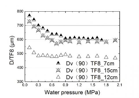
Figure 3. Diameter change curves of the droplets atomized by the TF8 nozzle at the spray pressure
Based on the experimental results, the diameter change curves of the droplets atomized by the TF8 nozzle at the spray pressure (P) were plotted (Figure 3). As mentioned above, the droplet diameters include D[3][2], D[4][3], Dv(10), Dv(50) and Dv(90). According to the droplet size distribution patterns in Figure 3, the size of the Dv(90) droplet was the largest, followed in descending order by D[4][3], Dv(50) , D[3][2] and Dv(10). Whichever the diameter, the size of the atomized droplets always decreased with the increase in spray pressure. Of course, the decrease was limited in the droplets of any diameter. When the pressure of the TF8 nozzle reached 0.5~0.6MPa, the diameter change in the atomized droplets became insignificant. The trend signifies the presence of a critical value of nozzle pressure. For the TF8 nozzle, the critical pressure was considered as 0.5~0.6MPa. Any pressure increase beyond the critical value will not significantly reduce the diameter of atomized particles. To realize a major reduction in diameter, one should either replace the nozzle type or produce smaller droplets with a new model.
Then, the change patterns of droplet diameter were analysed by the atomization energy balance relationship of the droplets. Before the nozzle backpressure reached 0.5~0.6MPa, the kinetic energy at the nozzle exit mainly worked against the surface tension and viscous force. The backpressure is positively correlated with the work effect, and negatively with the droplet diameter. The decrease in droplet diameter widened the area of air-droplet contact, which facilitates the heat and mass exchanges.
When the pressure of the TF8 nozzle reached 0.5~0.6MPa, the diameter change in the atomized droplets became insignificant. In other words, the energy consumed to overcome the surface tension and viscous force remained unchanged, and the remaining energy was converted to the kinetic energy of the atomized droplets.
Moreover, the velocities of the atomized droplets gradually increased with the nozzle backpressure. The velocity increase shortened the duration of air-droplet contact, and impeded the heat and mass exchanges.
The TF6 nozzle and AM4 nozzle are similar to the TF8 in terms of the effect of spray pressure on the atomized droplet size. These two nozzles also have critical pressures, which respectively falls in the range of 0.5MPa~0.8MPa and 0.3MPa~0.5MPa.
Figures 4 (a)~(e) compare the dimensions (Dv(90), D[4][3], Dv(50), D[3][2] and Dv(10)) of the atomized droplets located at different distances (7cm, 12cm and 15cm) below the TF8 nozzle. It can be seen that the greatest dimensions appeared at 7cm, following by 15cm and 12cm in descending order.
In addition, the differences among these droplet dimensions at different distances exhibited a decline trend with the increase in nozzle backpressure. This is attributed to the stable distribution of droplet size resulted from the secondary atomization.
According to the liquid atomization mechanism, liquid atomization is a liquid fragmentation process under internal and external forces. Once the external force surpasses the surface tension and viscous force of the liquid, the liquid will be fragmented into many droplets. These droplets are so unstable that they will be atomized again into even smaller particles under the surrounding airflow.
(a)
(a)
(c)
(d)
(e)
Figure 4. Droplet sizes at different locations below the TF8 nozzle
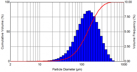
Figure 5 shows the distributions of droplet sizes at different distances below the TF8 nozzle. It is clear that a stable distribution of droplet sizes was formed at 12cm below the nozzle, indicating that secondary atomization occurred as the droplets fell from 7cm to 12cm below the nozzle (Figures 5(a)~(b)). During the continuous falling (Figures 5(b)~(c)), the droplets collided into each other, forming larger particles, due to the different sizes, settling velocities and accelerations. Compared with those at 7cm and 15cm below the nozzle, the droplet at 12cm below the nozzle boasted the mostly evenly distributed diameters (i.e. the smallest distribution span), and relatively consistent settling velocities. These conditions are beneficial for heat and mass exchanges between the air and droplets.
(a) Diameter distributions of particles at 7cm below the TF8 nozzle under 0.5MPa and 0.6MPa
(b) Diameter distributions of particles at 12cm below the TF8 nozzle under 0.5MPa and 0.6MPa
(c) Diameter distributions of particles at 15cm below the TF8 nozzle under 0.5MPa and 0.6MPa
Figure 5. Diameter distributions of the particles at different locations below the TF8 nozzle
Next, the author analysed the experimental data of the atomization features of the nozzles. The analysis reveals that the secondary atomization always occurred regardless of the nozzle type, an evidence to the universality of the phenomenon.
Figure 6 shows the size distributions of the particles at 10cm below the AM4 nozzle under 0.3MPa and 0.5MPa. It can be seen that the particle diameter distributions were stable under both pressures, which indicates that the secondary atomization location is stable when the AM4 nozzle is used.
(a) Diameter distribution of particles at 10cm below the AM4 nozzle under 0.3Mpa
(b) Diameter distribution of particles at 10cm below the AM4 nozzle under 0.5MPa
Figure 6. Diameter distributions of particles at 10cm below the AM4 nozzle under different pressures
The experiments on the TF6 nozzle, TF8 nozzle and AM4 nozzle were performed under different pressures. The results show that a stable secondary atomization location always existed regardless of the nozzle type. The location was 7cm below the nozzle for TF6 nozzle, 12cm below the nozzle for TF8 nozzle, and 10cm below the nozzle for AM4 nozzle. Therefore, secondary atomization is not an accidental phenomenon but a universal and stable one.
The ρa, σ, ρl and μ are constant under a constant temperature. Under the experimental air temperature of 20˚C and water temperature of 35˚C, ρa =1.205 kg/m3, σ=0.070435 N/m, ρl =993.95 kg/m3 and μ=0.7274×10⁻³ Pa·s. The maximum diameter of the TF8 nozzle (d0) is 3.18 mm. For particles at 12cm below the TF8 nozzle, the regressed correlations of the various diameters are as follows. Note that 12cm below the nozzle is the location of secondary atomization, the cause of stable diameter distribution.
$\frac{D_{[3][2]}}{d_{0}}=0.0587 W e^{-0.2754} R e^{0.0528}$
$r e s=-0.0024, r_{1}=-0.9308, r_{2}=-0.9798$ (3)
$\frac{D_{[4][3]}}{d_{0}}=0.0593 W e^{-0.07766} R e^{0.0601}$
$r e s=-0.0059, r_{1}=-0.7870, r_{2}=-0.7804$ (4)
$\frac{D_{v(50)}}{d_{0}}=0.0719 W e^{-0.2270} R e^{0.0657}$
$r e s=-0.0040, r_{1}=-0.9404, r_{2}=-0.9831$ (5)
$\frac{D_{v(0)}}{d_{0}}=0.0398 W e^{-0.2985} R e^{0.0308}$
$r e s=-0.0015, r_{1}=-0.9256, r_{2}=-0.9777$ (6)
$\frac{D_{v(90)}}{d_{0}}=0.0770 W e^{-0.0206} R e^{0.0776}$
$r e s=0.0286, r_{1}=-0.8535, r_{2}=-0.9066$ (7)
Table 4 lists the parameter ranges in equations (3)~(7).
Table 4. Parameter ranges
|
Parameter |
P (MPa) |
Particle diameter (μm) |
We |
Re |
||||
|
D[3][2] |
D[4][3] |
Dv(50) |
Dv(10) |
Dv(90) |
||||
|
Applicable range |
0.1-2.0 |
90.95-197.7 |
290.4-333.2 |
166-305.2 |
42.08-100.9 |
531.3-662.6 |
5.47-109.47 |
43,584.9-194,917.6 |
It is discovered that the droplet diameters decreased with the increase in spray pressure. However, the trend ceased to exist when the pressure exceeded a critical value. When the pressure reached the critical value, the diameter change in the atomized droplets became insignificant. In other words, the energy consumed to overcome the surface tension and viscous force remained unchanged, and the remaining energy was converted to the kinetic energy of the atomized droplets. Moreover, the velocities of the atomized droplets gradually increased with the nozzle backpressure. The velocity increase shortened the duration of air-droplet contact, and impeded the heat and mass exchanges.
Through the analysis of atomization features at different distances below each nozzle, it is concluded that the liquid fragmentation is so unstable that the droplets will be atomized again into even smaller particles under the surrounding airflow, resulting in a stable diameter distribution of the particles. The secondary atomization location facilitates the heat and mass exchanges between the air and droplets. The approximate locations of the secondary atomization are also determined in this research: the location is 7cm below the nozzle for TF6 nozzle, 12cm below the nozzle for TF8 nozzle, and 10cm below the nozzle for AM4 nozzle.
The least square method was used to fit the empirical correlation for droplets atomized by the three nozzles in the secondary atomization area. The empirical correlation was then converted to a functional relation of the Weber number and Reynolds number. The fitted empirical correlation can be used to predict the particle diameters from the nozzle exit and provide a theoretical basis for the design and application of nozzles of the same type.
This paper is made possible by the generous support from Nanjing Institute of Technology (Grant No. YKJ201406) and the National Natural Science Foundation of China (Grant No. 51408302).
[1] Cao J.M. (2002). On the theoretical prediction of fuel droplet size distribution in nonreactive diesel sprays, Journal of Fluids Engineering, Vol. 124, No. 1, pp. 182-185. DOI: 10.1115/1.1445140
[2] Liang Z.R., Luo X., Feng Y., Xu G.Q. (2015). Experimental investigation of pressure losses in a co-rotating cavity with radial inflow employing tubed vortex reducers with varied nozzles, Experimental Thermal and Fluid Science, Vol. 66, pp. 304-315. DOI: 10.1016/j.expthermflusci.2015.03.008
[3] Ferguson J.C., O'Donnell C.C., Chauhan B.S. (2015). Determining the uniformity and consistency of droplet size across spray drift reducing nozzles in a wind tunnel, Crop Protection, Vol. 76, pp. 1-6. DOI: 10.1016/j.cropro.2015.06.008
[4] Singh D., Premachandran B., Kohli S. (2015). Effect of nozzle shape on jet impingement heat transfer from a circular cylinder, International Journal of Thermal Sciences, Vol. 96, pp. 45-69. DOI: 10.1016/j.ijthermalsci.2015.04.011
[5] Ding H.B., Wang C., Chen C. (2015). Experimental and numerical studies on self-excited periodic oscillation of vapor condensation in a sonic nozzle, Experimental Thermal and Fluid Science, Vol. 68, pp. 288-299. DOI: 10.1016/j.expthermflusci.2015.05.002
[6] Von Lavante E., Kaya H., Winzösch F., Brinkhorst S., Mickan B. (2015). Flow structure in critical flow Venturi nozzle and its effect on the flow rate, Flow Measurement and Instrumentation, Vol. 44, pp. 97-106. DOI: 10.1016/j.flowmeasinst.2014.12.003
[7] Strotos G., Koukouvinis P., Theodorakakos A., Gavaises M., Bergeles G. (2015). Transient heating effects in high pressure diesel injector nozzles, International Journal of Heat and Fluid Flow, Vol. 51, pp. 257-267. DOI: 10.1016/j.ijheatfluidflow.2014.10.010
[8] Zacarías A., Venegas M., Lecuona A., Ventas R., Carvajal I. (2015). Experimental assessment of vapour adiabatic absorption into solution droplets using a full cone nozzle, Experimental Thermal and Fluid Science, Vol. 67, pp. 228-238. DOI: 10.1016/j.expthermflusci.2015.05.001
[9] Chong D.T., Zhao Q.B., Yuan F. (2015). Research on the steam jet length with different nozzle structures, Experimental Thermal and Fluid Science, Vol. 64, pp. 134-141. DOI: 10.1016/j.expthermflusci.2015.02.015
[10] Lan Z.K., Zhu D.H., Tian W.X. (2014). Experimental study on spray characteristics of pressure-swirl nozzles in pressurizer, Annals of Nuclear Energy, Vol. 63, pp. 215-227. DOI: 10.1016/j.anucene.2013.07.048
[11] Liu Y.S., Jiang Z., Wang D., Li X.H. (2014). Experimental research on the water mist fire suppression performance in an enclosed space by changing the characteristics of nozzles, Experimental Thermal and Fluid Science, Vol. 52, pp. 174-181. DOI: 10.1016/j.expthermflusci.2013.09.008
[12] Lefebvre A.H. (1989). Atomization and Sprays, CRC Press.
[13] Bayvel L.P., Orzechowski Z. (1993). Liquid Atomization, CRC Press.
[14] Liu L. (2001). Experimental and theoretical research on the atomization characteristics and two-phase flow fields of bubble atomizer nozzles, Tianjin University. DOI: 10.7666/d.y410760
[15] Chen B., Guo L., Zhang X. (2001). Experimental study on the atomization characteristics of nozzles, Journal of Engineering Thermophysics, Vol. 22, No. 2, pp. 237-240. DOI: 10.3321/j.issn:0253-231X.2001.02.030
[16] Liu W., Ma Q. (1997). Experimental study on atomization using a new-type air-assisted atomizer nozzle, Journal of Harbin University of Science and Technology, Vol. 2, No. 5, pp. 4-7.
[17] Zhang Z., Fan W., Yang M. (2003). Study on the atomization characteristics of a dual-orifice centrifugal nozzle, Journal of Engineering Thermophysics, Vol. 24, No. 1, pp. 153-156. DOI: 10.3321/j.issn:0253-231X.2003.01.047
[18] Liao Y., Qiu H., Huang Y. (2003). Study on the design methods for centrifugal nozzles, Petro-chemical Equipment, Vol. 32, No. 3, pp. 4-6.
[19] Liu N., Zhang X. (2005). Study on the atomization characteristics of pressure-type fine mist atomizer nozzles, Journal of Tongji University (Natural Science), Vol. 33, No. 12, pp. 1677-1679, 1684. DOI: 10.3321/j.issn:0253-374X.2005.12.025
[20] Kalla S., Marcoux H., Champlain A.D. (2015). CFD approach for modeling high and low combustion in a natural draft residential wood log stove, International Journal of Heat and Technology, Vol. 33, No. 1, pp. 33-38. DOI: 10.18280/ijht.330105
[21] Sivakumar A., Alagumurthi N., Senthilvelan T. (2015). Experimental and numerical investigation of forced convective heat transfer coefficient in nanofluids of Al2O3/water and CuO/EG in a serpentine shaped microchannel heat sink, International Journal of Heat and Technology, Vol. 33, No. 1, pp. 155-160. DOI: 10.18280/ijht.330121
[22] Ansari M.M., Chakrabarti A., Iqbal M.A. (2016). Effects of impactor and other geometric parameters on impact behavior of FRP laminated composite plate, Modelling, Measurement and Control A, Vol. 89, No. 1, pp. 25-44.
[23] Zhang F., Sun K. (2016). Tensorial biometric signal recognition based on multilinear PCA plus GTDA, Advances in Modelling and Analysis B, Vol. 59, No. 1, pp. 91-112.