OPEN ACCESS
An unconfined high turbulent swirling flow is investigated using Detached Eddy Simulation (DES) in a premixed vortex burner. The burner operates with propane-air mixture at high swirl number Sn = 1.05 under atmospheric pressure. In this analysis, the focus of the investigation is the isothermal flow and its expansion at the burner exit. Comparisons of experimental data show that the DES results are capable of predicting the unsteady flow structure and mean velocity profiles. DES results show that the swirling flow is responsible of the formation of a recirculation zone (CRZ) in the center of the burner exit. A helical precessing vortex core (PVC) is detected in the inner shear layer (ISL). Phase-angle analysis of the instantaneous flow field shows the presence of unsteady stagnation points strongly associated with PVC. In addition, phase-angle analysis of the radial profiles of the instantaneous velocities (u, w) is employed to clarify better the instantaneous flow field. The vortex core inside the PVC is analyzed using two slices perpendicular to its axis. It is found that the vortex core is characterized by the limits of its circumferential velocity u(R) and its radius R.
detached eddy simulation, precessing vortex core, swirl, vortex burner
Swirling flows are commonly used in modern gas turbine combustors to promote the flame stabilization and reduce pollutants emissions. Vortex breakdown that presents near the burner exit is a unique feature that characterizes the swirling flow. It leads to the formation of a central recirculation zone (CRZ), which puts the burned gases and the unburned reactants in a permanent mixing. This helps to operate the flame under high turbulent condition and consequently enhances the combustion. The CRZ is commonly associated with stagnation points and those often accompanied by the occurrence of coherent precessing vortex core (PVC). The PVC is characterized by its precessing around the symmetry axis of the burner [1]. Various studies have been conducted to investigate the effect of PVC on the stabilization of swirling flames. It was found that the PVC can enhance the fuel-air mixing [2] burned-unburned gases mixing [3] and it interacts with the thermo-acoustic oscillations of the flame [4]. PVCs are always encountered at isothermal conditions in gas turbine combustors [5-8]. In reacting conditions PVCs do not encountered in some particular combustors, or flame operating conditions [9,10].
Numerous experimental [11-15] and numerical [16-19] studies were investigated swirling flows features at an isothermal condition. Ceglia et al. [20] studied experimentally the three-dimensional flow field of a turbulent swirling jet in a model aero engine burn injector. The used injector operated with an isothermal water flow at Reynolds number Re = 50 × 103. They focused on the organization of the coherent structures arising within the near field of the swirling jet for both free and confined configurations. They reported, in both cases the instantaneous flow field is characterized by the presence of the PVC and of the outer helical vortex. They also note that the confined configuration dramatically alters the flow field topology, inducing an enhancement of turbulence at the nozzle exit and a more intense mixing. Bulat et al. [21] performed a computational study of isothermal confined swirling flow in an industrial gas turbine combustor, using Large Eddy Simulation (LES). Their isothermal LES results were found to be in good agreement with experimental data. They observed two separate structures inside the combustor: a PVC and a central vortex core (CVC). The two large scale flow features correspond to three-dimensional vortex structures with long lifetimes. The PVC found to be to a double helical structure and the second helical structure is weaker than the first. The CVC is formed at the tail end of the inner recirculation zone and precesses around the center axis in the same direction as the PVC. HongDa et al. [22] studied the non-reacting unconfined flow fields with and without swirl of a Cambridge swirl burner using LES. The burner consists of two annular slots surrounding a central bluff-body. Their results show that the annular swirling flow has a minor impact on the formation of the bluff-body recirculation zone. They observed that the formed 3D vortex structures near the shear layers, display ring structures in non-swirling flow and helical structures in swirling flow near the burner exit. The analysis of the helical structures reveals that flow fields contain co-existing helical and toroidal shaped coherent structures. The helical structure is associated with the PVC and it’s the most energetic dynamic flow structure. The toroidal structure has lower energy content which indicates that it is a secondary structure. LES technique is applied by Garcia-Villalba et al. [23] to model the non-reacting flow in a swirl burner. The configuration consisted of two unconfined co-annular jets, a main jet and a pilot jet characterized by a swirl number of 2. Two cases were studied differing with respect to the axial location of the inner pilot jet. They found that the flow presents very different coherent structures depending on each location of the inner pilot jet. The retracted location of the inner jet leads to the formation of very strong coherent structures which produce pronounced peaks in the spectra of velocity fluctuations. Other LES study was performed by Garcia-Villalba et al. [24] to investigate the effect of swirl number on the formation of coherent structures of a free annular swirling jet. In addition, the effect of added co-annular pilot jet on coherent structures was analyzed. The provided results indicated the presence of a weak PVC in the inner shear layer (ISL) at low swirl numbers Sn = 0.4 and 0.55. With increasing swirl number beyond 0.7, the PVC becomes more complex and a secondary coherent structure appears in the outer shear layer (OSL) of the flow. The addition of an axial pilot jet near the axis affects slightly the structures to be less coherent and much thinner. The introduction of swirl to the pilot jet has a dramatic impact on the flow, which leading to an almost entire removal of coherent structures. Roux et al. [25] used a jointly LES and acoustic analysis to study the non-reacting flow in a swirled premixed combustor. They computed a full geometry of the combustor, from plenum inlet to atmosphere to avoid any possible bias effect or tuning exercises of boundary conditions during LES/experiments comparison. A good agreement was found for both mean flow and the unsteady activity. They reported that the RMS fluctuation levels are very intense around the axis, close to the inlet of the combustion chamber. This activity it is actually due to the large-scale hydrodynamic structure PVC. It was indicated that the PVC rotates around the burner axis at a frequency of 540 Hz, which is very close to the dominant frequency of 510 Hz measured inside the chamber.
In this paper, Detached Eddy Simulation (DES) is performed to analyze the high turbulent swirling flow in a model vortex burner of Fernandes et al. [12]. The study scrutinizes the ability of DES to capture highly unsteady flow features and precessing coherent structures inside such vortex burner. To extensively analyze the mean flow, the unsteady activities and flow features including CRZ, ISL and OSL are also investigated. In addition, a particular attention is given to the PVC present in the expansion plane of the burner. The tested case investigates the isothermal unconfined air flow under high swirl number of 1.05. DES predictions are compared with measurements and give a satisfactory result. Phase-angle method is used to analyze the unsteady flow by means of streamlines, contours and profiles. Meanwhile, the PVC is characterized by the determination of some parameters, such as the vortex radius R and its corresponding velocity u(R).
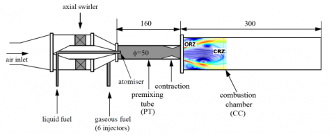
The model vortex burner of Fernandes et al. [12] used in this work consists of a swirl generator with variable blade angles to control the degree of swirl (Figure 1). To discharge into the combustion chamber (CC), the swirling flow passes through a premixing tube (PT). Liquid fuel (Jet-A1) can be introduced through an atomizer positioned on the centerline of the PT, as reported by Anacleto et al. [26]. Gaseous fuel (Propane) is used as a substitute for jet fuel and is injected upstream of the PT. The premixing tube ends with a contraction from a diameter of 50 mm to D = 40 mm. The contraction section prevents flame flashback when the combustor is operated in reactive case. The CC is made of cylindrical stainless steel ducts with an inner diameter of 110 mm and a total length of 300 mm. The model burner, shown in Figure 1 was studied by Anacleto et al. [26, 27] and Mansouri et al. [28] for reacting flow and by Cala et al. [11] and Fernandes et al. [12] for non-reacting flow.
The Reynolds number is based on the throat diameter of the contraction D = 40 mm and averaged velocity U0. Typical velocity and precession frequency were U0 = 30 m/s and f = 420 Hz, corresponding to Re = 8×10⁴. The swirling intensity is characterized through the swirl number based on the swirler geometry, accordingly to Gupta et al. [29]:
$S_{n}=\frac{2}{3}\left[\frac{1-\left(D_{1} / D_{2}\right)^{3}}{1-\left(D_{1} / D_{2}\right)^{2}}\right] \tan \varphi$ (1)
where D1 = 90 mm is the diameter of the central hub supporting the blades, D2 = 120 mm is the external diameter of the swirler, and φ is the blade angle.
Figure 1. Schematic diagram of the experimental combustor
During the experiments, a high swirl number equal to 1.05 is used and corresponds to the swirler blade angel 50°. The generated high swirling flow passes through the PT and followed by a sudden expansion into the CC. The swirling flow in the CC exhibits two distinctive zones as shown in Figure 1. The outer recirculation zone (ORZ) is formed in the burner exit at the CC corner as a result of the confinement and the CRZ corresponds to the vortex breakdown.
ANSYS-Fluent 14 CFD software is used for the simulations. It uses the finite-volume method to solve the governing equations. The SIMPLE algorithm is applied for the pressure-velocity coupling. A second order upwind scheme is used for all equations. Convergence criteria are set to 10-5 for all equations. The continuity and Navier-Stokes governing equations for compressible flow are ensemble averaged (URANS) near-wall regions and filtered (LES) in the rest of the flow using DES hybrid model to combine the best aspects of RANS and LES methodologies in a single solution strategy. The used RANS equations are based on the Shear Stress Transport (SST) Model of Menter [30]. The SST model is one of the eddy-viscosity models and it combines both advantages of k-ϵ and k-ω turbulence models. The details of DES strategy can be found in Spalart et al. [31] and Strelets [32].
3.1 Boundary conditions
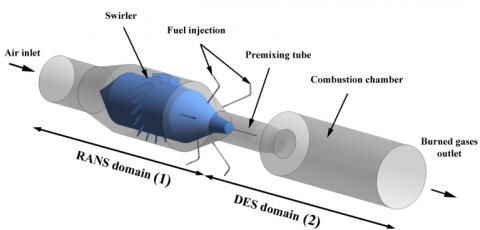
The computational domain replicates the experimental setup discussed above without any geometrical simplifications, as presented in Figure 2. The computational domain is divided in tow sub-domains. The first covers the air inlet, the swirl generator and the fuel injection duct. The second covers the premixing tube including the contraction and a fraction of the atmosphere at the burner exit. Note that the CC is not included to the domain in order to respect the unconfined condition. The air is introduced for both sub-domains and the fuel is not included in isothermal calculations. The present DES computations focus on the second sub-domain which contains the highly unsteady flow features and precessing coherent structures. Primarily, the first sub-domain is simulated using RANS strategy in order to generate realistic inlet boundary conditions to initialize the flow in the second sub-domain and avoid the constant uniform inlet velocities. Additionally, using the RANS strategy in the first sub-domain is for saving computational effort. The inlet boundary conditions involve profiles of the three velocity components, turbulent kinetic energy and eddy dissipation rate based on data at the outlet of the first sub-domain. All walls are treated with a log-law wall function, and non-slip adiabatic conditions are applied. A single outlet surface is applied with a commonly used specified constant pressure. This applied condition is recommended where no swirling motion is usually present at the outflow plane which is the same case in the present computations.
Figure 2. Computational domains with highlighted RANS and DES regions
3.2 Computational grid
The multi-block technique is used to generate a structured grid. The studied second sub-domain consists of 35 blocks and contains 3 million hexahedral grid cells. The suitable minimum grid spacing in x, y and z directions is calculated accordingly to the estimated Taylor turbulent microscale λ ~ D/52 in regions of potential turbulence generation and large velocity gradients. Due to the grid influence upon the results, the grid spacing is adjusted to be Δx,y,z ~ D/72. The used adjusted grid spacing gives a satisfactory results and good agreement with experimental data, as documented by Mansouri et al. [33]. Moreover, no need to solve the flow via a grid sensitivity analysis.
As the full resolution of the near-wall flow is not practical for high Reynolds number flows, the enhanced wall treatment is applied to model the flow in near-wall regions, as an advantage of DES strategy. For all solid boundaries, the first grid points are positioned at an averaged wall-normal distance of y+ = 1. At this value the grid is fine enough to be able to resolve the viscous sublayer, then the enhanced wall treatment turn on to model the fully-turbulent region of the boundary layer.
Figure 3. Numerical grid of the second sub-domain (inlet boundary in blue and walls in black)
4.1 Time averaged and instantaneous flow fields
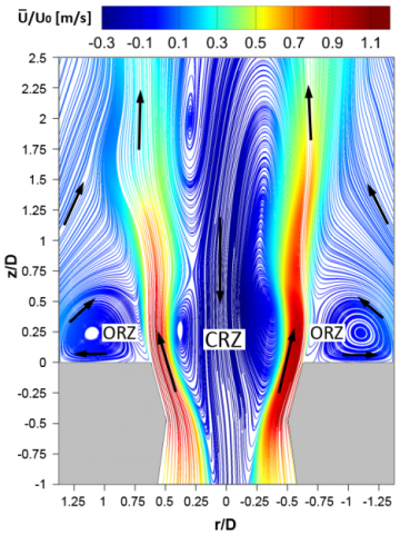
Figure 4 presents the two-dimensional averaged flow field on the streamwise plane through the vortex burner, using streamline patterns colored by averaged axial velocity (with U0=30 m/s). The sudden expansion of the flow at the burner exit induces two recirculation zones, as expected from a turbulent swirling flow [34]. The first, CRZ is cone-shaped reverse flow stream extending from the burner exit along the axial direction as result of vortex breakdown. The second, ORZ is formed at the plane wall of the burner due to its geometry which the swirling jet encounters when expands. It is shown that the sudden expansion induces also strong velocity gradients up to 1.1U0 that determine the presence of an inner shear layer (ISL) and an outer shear layer OSL. It can be seen that there exists a strong entrainment of the free flow into the OSL of the swirling flow.
Figure 4. The streamline patterns of the averaged flow field on the streamwise plane.
Figure 5 shows the two-dimensional instantaneous flow field on the streamwise plane through the vortex burner, using streamline patterns colored by instantaneous axial velocity. It is clearly shown that the instantaneous flow field contains specific features that are not present in the averaged flow field. The most specific features compared to the averaged flow field are the vortices in the ISL marked by black arrows, which are arranged as a zig-zag marked by white dashed line. This arrangement confirms the existence of a helical 3D coherent vortex in the ISL. The helical vortex is known as the Precessing Vortex Core (PVC). Other features located in the ISL of the instantaneous flow field are associated frontally to the vortices of the ISL, such as the stagnation points marked by red dots. They formed as a result of the collision between the arrangements of vortices in the ISL. The vortices in the OSL are particular features that relevant to the present flow field. All those discussed features are related strongly to the PVC as it will be seen in Section 4.5.
Figure 5. The streamline patterns of the instantaneous flow field on the streamwise plane.
4.2 Validation with experimental measurements
It’s appropriate to notice that the typical averaged velocity in contraction U0 = 30 m/s corresponding to D = 40 mm, are used as reference of computational non-dimensional results. In Fernandes et al. [12], the measurements of averaged velocity profiles are provided in only one location z = 0.25D. Figure 6 illustrates comparisons between LDV measurements [12] and present predicted averaged axial (a) and averaged swirling (b) velocity profiles close to the expansion zone at z = 0.25D. In Figure 6.a, the present DES strategy could be capable of capturing the averaged flow field structures. This is clearly seen close to the burner center (r/D = 0), where the negative values present the CRZ and also close to r/D = 0.5 where the velocity peak present the shear layer between the IRZ and the ORZ. Meanwhile, in Figure 6.b the DES results show the same tend of the averaged swirling velocity profile with the exact values between r/D = 0 and r/D = 0.5 and close to r/D = 1 too. Moreover, the predictions of the radial profiles of the both velocities are all in good agreement with experimental measurements. Far off from the expansion zone (z/D = 1.75), additional profiles of both averaged velocities are presented. This gives an idea about the flow structure in this region. The flow starts to be weak and the velocity peaks are decreased around 50% (about 0.5 U0) compared with the validation location.
Figure 6. Radial profiles of averaged axial (a) and averaged swirling (b) velocities.
Figure 7. Phase angles of the instantaneous flow field
4.3 Phase-angle analysis of the flow field
In Figure 7 the instantaneous flow field along the streamwise plane of the burner is extensively analyzed using the phase-angle technique. The flow field is characterized using streamline patterns at four phase angles φ = 0°, 45°, 90° and 135°. The phase angle φ is defined with respect to the periodic precession of the PVC. The stagnation points in the flow marked by red dots are linked with blue lines, in order to follow their manifestation at each phase angle. At φ = 0°, six stagnation points occurred in the flow and link the vortices. Four of them associate the vortices in the ISL and two associate the vortices in the OSL. The flow structure shows a difference at φ = 45° with new revealed stagnation points in both ISL and OSL. Two raised points in the ISL at around z/D = -1 in the contraction section and at z/D = 1.75. The first is related to the PVC and the second is related to the interaction between the extended swirling flow and the free flow. Additional stagnation point is appeared in the OSL as a result of the interaction between the entrained free flow and the OSL, it located at z/D = 0.75. Moreover, at φ = 90° one point in the ISL is disappeared and the positions of the other points almost stay the same and no considerable difference is observed, except the point in the contraction section which is moved forward by around 0.25D compared with its last position at φ = 45°. At the last phase angle φ = 135°, the flow structure differed considerably comparing with the two previous angles, and it tends to have the same positions of the stagnation points, as at the initial phase angle φ = 0°. Therefore, another point is disappeared which was appeared in the location z/D = 0.75 in the OSL at φ = 45°. Meanwhile, the stagnation point of the contraction zone stays moving forward to be locates at about z/D = 0.4. This indicates the precessing motion of the PVC. Finally, the results demonstrate the high unsteady features of the turbulent swirling flow that are strongly associated with PVC.
4.4 Phase-angle analysis of the instantaneous velocity profiles
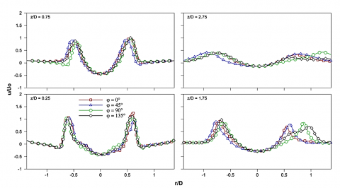
To detail the instantaneous flow field structure, radial profiles of the phase-angle instantaneous velocities (u, w) are plotted. Four locations z/D = 0.25, 0.75, 1.75 and 2.75 are shown in Figures 8 and 9, match longitudinal positions at which results are taken from the computations. At these locations, the flow exhibits a significant contrast. From Figure 8, the axial velocity in the centre (r/D > 0) and in the ORZ (r/D > 0.75) remains almost constant at the first two locations z/D = 0.25 and 0.75. For the last two locations z/D = 1.75 and 2.75, in the ORZ the phase-angle variations are changed; whereas the velocity peaks are shifted to that zone for φ = 90° and 135° at z/D = 1.75 and for φ = 45° and 90° at z/D = 2.75. However, the phase-angle variations manifest in the maximum axial velocity being reached at the shear layer in different phases, and its corresponding radial extent. This might be explained by the high level of unsteadiness in the shear layer region.
In Figure 9, the swirling velocity component exhibits shows higher phase-angle variations compared to the axial component. The phase angle at which the maximum and minimum velocities are reached manifests strongly in the locations z/D = 0.25, 0.75 and 1.75. At the location z/D = 2.75, the swirling flow becomes very weak and a relatively flat profiles are observed. The profiles at φ = 0° indicates the highest instantaneous swirling velocity, whereas the profiles at φ = 90° indicates the lowest instantaneous swirling velocity.
Figure 8. Radial profiles of the phase-angles instantaneous values of the axial velocity
Figure 9. Radial profiles of the phase-angles instantaneous values of the swirling velocity.
4.5 Precessing vortex core (PVC)
As previously discussed in Section 4.1, it is clearly visible that the vortex structures in the ISL which propagate in time are ordered in a zigzag arrangement. These vortices are formed inside the contraction section of the premixing tube (PT). This phenomenon is a strong indication of the formation of a PVC which is a typical instability in high swirling flows [35]. Figure 10.a shows an instantaneous view of the PVC using a low pressure isosurface colored by instantaneous axial velocity. It can be seen that in the contraction section, the instability sets on and the PVC is formed taking on a helical shape. The direction of the resulting precession is the direction of the swirler itself. It is desirable to determine some parameters for the PVC, such as the vortex radius R and its corresponding velocity u(R). Figure 10.b presents vectors of the flow fields in two slices perpendicular to the vortex axis. The vortex centerlines (marked with the dashed black line) with velocity gradient from high at the left to low at the right in the primary slice with the inversion of this gradient in the secondary slice, can be seen. The axial velocity profiles across the vortex centerlines are plotted in Figure 11. The profiles of both slices show that the vortex is limited by its maximum and minimum circumferential velocity u(R). The locations of the circumferential velocity limits of the vortex and the zero velocity at the vortex center, defines the PVC radius R. The minimum and maximum u(R) with corresponding R characterize the coherent-body rotation of the PVC. By taking the case of the secondary slice profile, the minimum u(R) = -0.23 locates at r/D = 0.33 and the maximum u(R) = 1.05 locates at r/D = 0.59. This indicates that the coherent-body exhibits a non-symmetric rotation around the axis of the vortex. Indeed, it can be seen that the rotation center locates at r/D = 0.42, which does not correspond to the average value between the minimum and maximum u(R) locations.
Figure 10. The PVC (a) and vectors of the flow fields in two slices across the PVC (b) velocity
Figure 11. Velocity profiles across the vortex centrelines of the two slices.
The present study focused on DES computations of isothermal flow fields in premixed vortex burner under unconfined conditions. The burner is operated with air at atmospheric pressure and under high swirl number Sn = 1.05. The multi-block technique is used to generate a structured grid of the vortex burner. The flow fields are characterized using streamline patters colored by axial velocity. The following conclusions can be drawn from the present computations:
a) The applied DES strategy is useful to capture the averaged flow field with CRZ and ORZ, as well as the specific features of the instantaneous flow filed such as the vortices and the stagnation points in the ISL. PVC is detected in the shear layer of the CRZ.
b) The isothermal DES results are found to be in good agreement with experimental data of averaged axial velocity and averaged swirling velocity profiles.
c) A phase-angle analysis of the instantaneous flow field show that the PVC further induces an unsteady stagnation points. The motion of the stagnation points is linked to the periodic precession of the PVC.
d) A phase-angle analysis of the instantaneous velocity profiles of u and w, indicate that the variations manifest in the maximum axial velocity being reached at the shear layer in different angles. The swirling velocity component indicates higher strongest phase-angle variations.
e) The PVC is formed from the contraction to the burner exit and taking on a helical shape. It is visualized using a low pressure isosurface. The direction of the PVC precession is the direction of the swirler itself.
Vectors of the flow fields in two slices across the vortex axis are presented. The circumferential velocity profiles of the vortex centerlines show that the vortex is characterized by the limits of its circumferential velocity u(R) and its corresponding radius R.
|
f |
Frequency |
|
k |
Kinetic energy |
|
Re |
Reynolds number |
|
R |
Radius |
|
Sn |
Swirl number |
|
u |
Mean Axial velocity |
|
w |
Mean Swirl or tangential velocity |
|
x |
Axial location |
|
y+ |
Wall distance vector |
|
y |
Radial location |
|
Greek symbols |
|
|
ε |
Turbulent dissipation |
|
φ |
Phase angle |
|
ω |
Turbulent frequency |
[1] Syred N. (2006). A review of instability and oscillation mechanisms in swirl combustion systems, Prog. Energy. Combust. Sci., Vol. 32, pp. 93-161. DOI: 10.1016/j.pecs.2005.10.002
[2] Galley D., Ducruix S., Lacas F., Veynante D. (2011). Mixing and stabilization study of a partially premixed swirling flame using laser induced fluorescence, Combust. Flame., Vol. 158, pp.155-171. DOI: 10.1016/j.combustflame.2010.08.004
[3] Stöhr M., Boxx I., Carter C.D., Meier W. (2012). Experimental study of vortex-flame interaction in a gas turbine model combustor, Combust. Flame., Vol. 159, pp. 2636-2649. DOI: 10.1016/j.combustflame.2012.03.020
[4] Steinberg A.M., Arndt C.M., Meier W. (2013). Parametric study of vortex structures and their dynamics in swirl-stabilized combustion, Proc. Combust. Inst., Vol. 34, pp. 3117-3125. DOI: 10.1016/j.proci.2012.05.015
[5] Jakirlic S., Kniesner B., Kadavelil G., Gnirß M., Tropea C. (2009). Experimental and computational investigations of flow and mixing in a single-annular combustor configuration, Flow. Turbul. Combust., Vol. 83, pp. 425-448. DOI: 10.1007/s10494-009-9229-8
[6] Widenhorn A., Noll B., Stöhr M., Aigner M. (2007). Numerical investigation of a laboratory combustor applying hybrid RANS-LES methods, Symposium of Hybrid RANS-LES Methods, Corfu, Greece.
[7] Shtork S.I., Cala C.E., Fernandes E.C. (2007). Experimental characterization of rotating flow field in a model vortex burner, Exp. Therm. Fluid. Sci., Vol. 31, pp. 779-788. DOI: 10.1016/j.expthermflusci.2006.08.008
[8] Valera-Medina A., Syred N., Griffiths A. (2009). Visualisation of isothermal large coherent structures in a swirl burner, Combust. Flame., Vol. 156, pp. 1723-1734. DOI: 10.1016/j.combustflame.2009.06.014
[9] Terhaar S., Oberleithner K., Paschereit C.O. (2015). Key parameters governing the precessing vortex core in reacting flows: An experimental and analytical study. Proc. Combust. Inst. Vol. 35, pp. 3347-3354. DOI: 10.1016/j.proci.2014.07.035
[10] Oberleithner K., Stöhr M., Im S.H., Arndt C.M., Steinberg A.M. (2015). Formation and flame-induced suppression of the precessing vortex core in a swirl combustor, experiments and linear stability analysis, Combust. Flame., Vol. 162, pp. 3100-3114. DOI: 10.1016/j.combustflame.2015.02.015
[11] Cala C.E., Fernandes E.C., Heitor M.V., Shtork S.I. (2006). Coherent structures in unsteady swirling jet flow, Exp. Fluids., Vol. 40, pp. 267-276. DOI: 10.1007/s00348-005-0066-9
[12] Fernandes E.C., Heitor M.V., Shtork S.I. (2006). An analysis of unsteady highly turbulent swirling flow in a model vortex combustor, Exp. Fluids., Vol. 40, pp. 177-187. DOI: 10.1007/s00348-005-0034-4
[13] Fureby C., Grinstein F.F., Li G., Gutmark E.J. (2007). An experimental and computational study of a multi-swirl gas turbine combustor, Proc. Combust. Inst., Vol. 31, pp. 3107-3114. DOI: 10.1016/j.proci.2006.07.127
[14] Legrand M., Nogueira J., Lecuona A., Nauri S., Rodriguez P.A. (2010). Atmospheric low swirl burner flow characterization with stereo PIV, Exp. Fluids., Vol. 48, pp. 901-913. DOI: 10.1007/s00348-009-0775-6
[15] Schneider C., Dreizler A., Janicka J. (2005). Fluid dynamical analysis of atmospheric reacting and isothermal swirling flows, Flow. Turbul. Combust., Vol. 74, pp. 103-127. DOI: 10.1007/s10494-005-7369-z
[16] Yang Y., Kær S.K. (2012). Large-eddy simulations of the non-reactive flow in the Sydney swirl burner, Int. J. Heat. Fluid. Fl., Vol. 36, pp. 47-57. DOI: 10.1016/j.ijheatfluidflow.2012.02.008
[17] Jochmann P., Sinigersky A., Hehle M., Schafer O., Koch R., Bauer H.J. (2006). Numerical simulation of a precessing vortex breakdown, Int. J. Heat. Fluid. Fl., Vol. 27, pp. 192-203. DOI: 10.1016/j.ijheatfluidflow.2005.08.003
[18] Al-Abdeli Y.M., Masri A.R. (2003). Recirculation and flow field regimes of unconfined non-reacting swirling flows, Exp. Therm. Fluid. Sci., Vol. 27, pp. 655-665. DOI: 10.1016/S0894-1777(02)00280-7
[19] Wegner B., Staufer M., Sadiki A., Janicka J. (2007). Study of flow and mixing in a generic GT combustor using LES, Flow. Turbul. Combust., Vol. 79, pp. 389-403. DOI: 10.1007/s10494-007-9105-3
[20] Ceglia G., Discetti S., Ianiro A., Michaelis D., Astarita T., Cardone G. (2014). Three-dimensional organization of the flow structure in a non-reactive model aero engine lean burn injection system, Exp. Therm. Fluid. Sci., Vol. 52, pp. 164-173. DOI: 10.1016/j.expthermflusci.2013.09.007
[21] Bulat G., Jones W.P., Navarro-Martinez S. (2015). Large eddy simulations of isothermal confined swirling flow in an industrial gas-turbine, Int. J. Heat. Fluid. Fl., Vol. 51, pp. 50-64. DOI: 10.1016/j.ijheatfluidflow.2014.10.028
[22] Zhang H., Han C., Ye T., Zhang J., Chen Y. (2015). Large eddy simulation of unconfined turbulent swirling flow, Sci. China. Technol. Sci., Vol. 58, pp. 1731-1744. DOI: 10.1007/s11431-015-5912-2
[23] Garcia-Villalbal M., Frohlich J., Rodi W. (2007). Investigation of the Influence of the inlet geometry on the flow in a swirl burner, High Performance Computing in Science and Engineering ’06, Springer Berlin Heidelberg. DOI: 10.1007/978-3-540-36183-1_28
[24] Garcia-Villalba1 M., Frohlich J. (2006). LES of a free annular swirling jet - Dependence of coherent structures on a pilot jet and the level of swirl, Int. J. Heat. Fluid. Fl. Vol. 27, pp. 911-923. DOI: 10.1016/j.ijheatfluidflow.2006.03.015
[25] Roux S., Lartigue G., Poinsot T., Meier U., Bérat C. (2005). Studies of mean and unsteady flow in a swirled combustor using experiments, acoustic analysis, and large eddy simulations, Combust. Flame. Vol. 141, pp. 40-54. DOI: 10.1016/j.combustflame.2004.12.007
[26] Anacleto P.M., Heitor M.V. (2001). A laser doppler analysis of the impact of flow boundary conditions on the performance of a model lean premixed combustor, 10th International Symposium on Application of Laser Techniques to Fluid Mechanics, Lisbon, Portugal.
[27] Anacleto P.M., Fernandes E.C., Heitor M.V., Shtork S.I. (2003). Swirl flow structure and flame characteristics in a model lean premixed combustor, Combust. Sci. Technol. Vol. 175, pp. 1369-1388. DOI: 10.1080/00102200302354
[28] Mansouri Z., Aouissi M., Boushaki T. (2016). A Numerical study of swirl effects on the flow and flame dynamics in a lean premixed combustor, Int. J. Heat. Technol., Vol. 34, pp. 227-235. DOI: 10.18280/ijht.340211
[29] Gupta A.K, Lilley D.G., Syred N. (1984). Swirl Flows, Abacus Press, London.
[30] Menter F.R. (1994). Two-equation eddy-viscosity turbulence models for engineering applications, AIAA J., Vol. 32, pp. 1598-1605. DOI: 10.2514/3.12149.
[31] Spalart P.R., Jou W.H., Strelets M., Allmaras S.R. (1997). Comments on the feasibility of LES for wings, and on a hybrid RANS/LES Approach, Advances in DNS/LES, Proceeding of the First AFOSR International Conference on DNS/LES, Greyden Press, Louisiana, USA.
[32] Strelets M. (2001). Detached eddy simulation of massively separated flows, 39th AIAA Aerospace Sciences Meeting and Exhibit, Reno NV, USA.
[33] Mansouri Z., Aouissi M., Boushaki T. (2016). Detached eddy simulation of high turbulent swirling reacting flow in a premixed model burner, Combust. Sci. Technol., Vol. 188, pp. 1777-1798. DOI: 10.1080/00102202.2016.1211888
[34] Li S., Zhongguang F., Yazhou S., Ruixin W., Hui Z. (2016). LES of swirl angle on combustion dynamic and NOx formation in a hybrid industrial combustor, Int. J. Heat. Technol. Vol. 34, pp. 197-206. DOI: 10.18280/ijht.340207
[35] Shi L., Fu Z.G., Shen Y.Z., Wang R.X., Zhang H. (2016). Large Eddy simulation of the PVC behavior in both non-reacting and reacting flows with different Reynoldnumbers, International Journal of Heat and Technology, Vol. 34, No. 3, pp. 429-438. DOI: 10.18280/ijht.340312