OPEN ACCESS
The present investigation deals with the case of an Ag (CuO or Al2O3)-water nanofluid’ convection phenomenon within a square enclosure, which including two heated sources, of a square shape. To do so, a computer code, based on the finite volume approach and the SIMPLER algorithm, is adopted to solve the general coupled equations. By studding the impact of some pertinent parameters such the Rayleigh number, the heaters’ vertical location within the enclosure, as well as the nanoparticles’ volume fraction and its type on the nanofluid flow and heat behaviors, the numerical predictions proved the nanoparticles type is the key factor for the heat transfer enhancement within such industrial geometry, side by side with the increasing function of the Rayleigh number and the nanoparticles’ volume fraction. Unlike the latter, the increase in the heaters’ vertical location within the enclosure affects the nanofluid flow, but it has no significant impact on the mean transfer rate.
natural convection, square enclosure, Ag-water nanofluid, CuO-water nanofluid, AL2O3-water nanofluid, square heaters, finite volume approach
Heat convection of nanofluids, which are a mixture of nanoparticles and a base fluid; such Water and Oil, has been recently an active field of research since they are used to improve the transfer rate of industrial processes. Compared to other techniques for enhancing the heat transfer in practical applications, nanofluids have the advantage of behaving like pure fluids reason to the nanometric size of the introduced particles. Thus, it’s adopted in various applications such advanced nuclear systems or micro/mini channel heat sinks, electronic equipment as power transistors, printed wiring boards and chip packages mounted on computer motherboards.
Back in time, and up to 1995, some papers dealing with natural convection phenomenon of nanofluids within differentially heated enclosures were very helpful for our beginning [1-4]. A review of the literature indicates that numerous industrial geometries were investigated [5-9] but almost works were done using rectangular configurations [10-12].
Khanafer et al. [13] studied the transfer performance of some nanofluids into a rectangular enclosure. Their results proved that the heat transfer rate, at any given Grashof number, is an increasing function of the nanoparticles’ volume fraction. Additionally, the variances within different models, based on the thermophysical properties of the used nanofluid, have substantial effects on the numerical predictions. The authors proposed then, their new correlations to predict the mean transfer rate within such enclosure for various values of the Grashof number and the nanoparticles’ volume fraction. Tiwari and Das [14] investigated numerically the behavior of nanofluids inside a two-sided’ lid-driven square enclosure, governed by a horizontal thermal gradient. Using the finite volume method, the researchers developed a new model to predict the thermal behavior of nanofluids within such industrial geometry; taking into account the solid volume fraction.
A year after, Oztop and Abu-Nada [15] undertook a numerical study of natural convection phenomenon within a rectangular enclosure, partially heated from it left side wall, by considering various nanofluids, such as Cu-water, TiO2-water and Al2O3-water as well. The right wall was maintained at a constant temperature; lower than that of the left discrete source, when the other walls were supposed adiabatic. Their results displayed the increasing function of the heat transfer with the nanoparticles’ volume fraction, proving at the same time, that using Cu nanoparticles is more required for better heat transfer within such configuration. As far as the left discrete source is increased, heat transfer rate is found to be pronounced as the source surface is getting larger. Then, higher aspect ratio between the active walls is more desired.
Muthtamilselvan et al. [16] studied the mixed convection phenomenon within a lid-driven enclosure; filled by a Cu-water nanofluid. The side walls were assumed to be insulated, when the bottom wall is kept at a constant temperature higher than that of the moving top one. Regarding these conditions, it was found that both; the aspect ratio and the solid volume fraction affect the flow pattern and the heat transfer of the convective fluid within the enclosure. Going far, Mahmoodi [17] investigated numerically the natural convection phenomenon within a partitioned square enclosure filled by nanofluids such as Cu-water, Ag-water and TiO2-water as well. The cavity’ side walls were assumed to be cold when a thin heater, for which both location and length were varying, was positioned inside the latter. With such investigation, Mahmoodi proved that the rate of heat transfer increases with the increase Rayleigh number and the nanoparticles volume fraction. At low Rayleigh values, the type of nanofluid does not affect the heat transfer whereas for high values of the latter, the heat transfer reaches its maximum values with the Ag-water nanofluid. The effect of the heater’s position on the mean transfer is found depends on the Rayleigh value and the increased length as well. A year after, Mahmoodi and Sebdani [18] inspected numerically the free convection of the Cu-water nanofluid inside a differentially heated square enclosure with an adiabatic square body; located in its centre. For various Rayleigh values, except the case of Ra = 104, the mean Nusselt number is found increases with the increase nanoparticles volume fraction.
Motivated by these works and many others, the purpose of our present work is to maintain the natural convection phenomenon within a square enclosure, filled by an Ag, CuO, or Al2O3-water nanofluid, and including two square heaters which mounted nearer the cold side walls at affixed distance of about 15% the cavity’ height. The numerical results will be presented in terms of pertinent parameters such as the Rayleigh number, the nanoparticles volume fraction as well as the heaters’ vertical distance. Such studied configuration is an interesting work for many industrial applications, especially in the Refining and Petrochemical fuels’ exchangers.
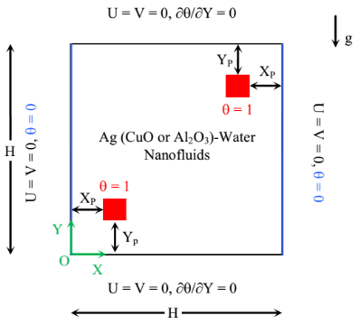
The problem under investigation, as shown in Figure 1, is a laminar, two dimensional natural convection within a square enclosure; having two isothermal square heaters, (of a width w equals 10% the cavity’ length), mounted nearer the side cold walls at a distance Xp = 0.15. the enclosure is assumed is assumed to be filled with an Ag, CuO, or Al2O3-water nanofluid, where the water and the chosen nanoparticles are in thermal equilibrium. The computational results are obtained for a wide range of the Rayleigh number and the nanoparticles volume fraction, when the heaters’ location Yp is ranging between 0.15 and 0.75. The constant thermo-physical properties of the base fluid and the nanoparticles are given in Table 1, whereas the nanofluid density variation in the buoyancy forces is determined using the Boussinesq approximation [19].
Figure 1. Simulation domain with its boundary conditions
Table 1. Thermo-physical properties of the base fluid and the nanoparticles at T = 25°C
|
Thermo-physical properties |
Fluid Phase (water) |
Ag |
CuO |
Al2O3 |
|
Cp (J/kg K) |
4179 |
235 |
531.8 |
761.55 |
|
r (kg/m3) |
997.1 |
10500 |
6320 |
3962 |
|
k (W/m K) |
0.613 |
429 |
20 |
37.17 |
|
b (1/K) 10-6 |
210 |
19.7 |
18 |
75 |
The nanofluid density, noted as ρnf, the heat’ capacity, (ρ Cp)nf, the thermal expansion’ coefficient, (ρ β)nf, as well as the thermal diffusivity, αnf, are defined respectively, as follows [13]:
ρnf = (1 - φ) ρf + φ ρs (1)
(ρCp)nf = (1 - φ) (ρ Cp)f + φ (ρ Cp)s (2)
(ρ β)nf = (1 - φ) (ρ β)f + φ (ρ β)s (3)
$\alpha_{\mathrm{nf}}=\frac{\mathrm{k}_{\mathrm{nf}}}{\left(\rho \mathrm{C}_{\mathrm{p}}\right)_{\mathrm{nf}}}$ (4)
For the dynamic viscosity, μnf, and the thermal conductivity, knf, Brinkman [20] and Maxwell-Garnett formulations [21] are adopted, respectively, as:
$\mu_{\mathrm{nf}}=\frac{\mu_{\mathrm{f}}}{(1-\varphi)^{2,5}}$ (5)
$\frac{\mathrm{k}_{\mathrm{nf}}}{\mathrm{k}_{\mathrm{f}}}=\frac{\left(\mathrm{k}_{\mathrm{s}}+2 \mathrm{k}_{\mathrm{f}}\right)-2 \varphi\left(\mathrm{k}_{\mathrm{f}}-\mathrm{k}_{\mathrm{s}}\right)}{\left(\mathrm{k}_{\mathrm{s}}+2 \mathrm{k}_{\mathrm{f}}\right)+\varphi\left(\mathrm{k}_{\mathrm{f}}-\mathrm{k}_{\mathrm{s}}\right)}$ (6)
The dimensionless conservation equations, describing the transport phenomenon inside the square, can be written as:
$\frac{\partial \mathrm{U}}{\partial \mathrm{X}}+\frac{\partial \mathrm{V}}{\partial \mathrm{Y}}=0$ (7)
$\mathrm{U} \frac{\partial \mathrm{U}}{\partial \mathrm{X}}+\mathrm{V} \frac{\partial \mathrm{U}}{\partial \mathrm{Y}}=-\frac{\partial \mathrm{P}}{\partial \mathrm{X}}+\frac{\mu_{\mathrm{nf}}}{\rho_{\mathrm{nf}} \alpha_{\mathrm{f}}}\left[\frac{\partial^{2} \mathrm{U}}{\partial \mathrm{X}^{2}}+\frac{\partial^{2} \mathrm{U}}{\partial \mathrm{Y}^{2}}\right]$ (8)
$\mathrm{U} \frac{\partial \mathrm{V}}{\partial \mathrm{X}}+\mathrm{V} \frac{\partial \mathrm{V}}{\partial \mathrm{Y}}=-\frac{\partial \mathrm{P}}{\partial \mathrm{Y}}+\frac{\mu_{\mathrm{nf}}}{\rho_{\mathrm{nf}} \alpha_{\mathrm{f}}}\left[\frac{\partial^{2} \mathrm{V}}{\partial \mathrm{X}^{2}}+\frac{\partial^{2} \mathrm{V}}{\partial \mathrm{Y}^{2}}\right]+\frac{(\rho \beta)_{\mathrm{nf}}}{\rho_{\mathrm{nf}} \beta_{\mathrm{f}}} \operatorname{Ra} \operatorname{Pr} \theta$ (9)
$\mathrm{U} \frac{\partial \theta}{\partial \mathrm{X}}+\mathrm{V} \frac{\partial \theta}{\partial \mathrm{Y}}=\frac{\alpha_{\mathrm{nf}}}{\alpha_{\mathrm{f}}}\left[\frac{\partial^{2} \theta}{\partial \mathrm{X}^{2}}+\frac{\partial^{2} \theta}{\partial \mathrm{Y}^{2}}\right]$ (10)
where Ra (= g β ∆T H3/αf νf) is the Rayleigh number, Pr (= νf/αf) is the Prandtl number.
The average rate of heat transfer across the side walls is expressed in dimensionless form by the Nusselt number as shown Eq. 11:
$\left|\mathrm{Nu}_{\mathrm{left} \text { wall }}\right|=\left|\mathrm{Nu}_{\text { right wall }}\right|=\left(\frac{\mathrm{k}_{\mathrm{nf}}}{\mathrm{k}_{\mathrm{f}}}\right) \int_{0}^{1}\left.\left(\frac{\partial \theta}{\partial \mathrm{X}}\right)\right|_{\text { wall }} \mathrm{d} \mathrm{Y}$ (11)
The governing conservation equations are discretized in space using the finite volume approach, when the convection-diffusion terms were treated with a Power-Law scheme. The resulting algebraic equations, with the associated boundary conditions, are then solved using the line by line method. As the momentum equation is formulated in terms of the primitive variables (U, V and P), the iterative procedure includes a pressure correction calculation method, namely SIMPLE modified [22] to solve the pressure-velocity coupling. Noted that the convergence criterion for temperature, pressure, and velocity is given as:
Error $=\frac{\sum_{j=1}^{m} \sum_{i=1}^{n}\left|\xi_{i, j}^{k+1}-\xi_{i, j}^{k}\right|}{\sum_{j=1}^{m} \sum_{i=1}^{n}\left|\xi_{i, j}^{k+1}\right|} \leq 10^{-6}$ (12)
where both m and n are the grid points numbers in X and Y directions, respectively. ξ is any of the computed field variables, k is the iteration number, i and j are nodes according to X and Y directions.
The performance of the using code via the natural convection of nanofluids is established by comparing its predictions with other numerical results, and by verifying the grid independence of the present results. First, the present results are consistent with previous computations, namely those of Ghia et al. [23] in terms of Streamlines within a square enclosure of an upper moving wall.
Figure 2 displays the fluid’ motion within such conditions as a function of Reynolds number such as 100, 400 and 1000 as well. As we can see, the present predictions present an identical solution with Ghia et al. [23].
(Re = 100)
(Re = 400)
(Re = 1000)
Ghia et al. [23] Present predictions
Figure 2. Fluid’ motion validation with Ghia et al. [23]
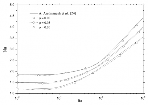
Figure 3. Mean Nusselt number of the cold square partitioned enclosure, a comparison with the results of Arefmanesh et al., [24]
Table 2. Average Nusselt number of the heat source, comparison with Oztop and Abu-Nada [15]
|
Ra |
φ |
Oztop and Abu-nada [15] |
Present study |
Relative gap (%) |
|
|
0.00 |
1.004 |
1.005 |
0.10 |
|
|
0.05 |
1.122 |
1.128 |
0.53 |
|
103 |
0.10 |
1.251 |
1.248 |
0.24 |
|
|
0.15 |
1.423 |
1.419 |
0.28 |
|
|
0.20 |
1.627 |
1.621 |
0.37 |
|
|
0.00 |
2.010 |
2.032 |
1.08 |
|
|
0.05 |
2.122 |
2.109 |
0.61 |
|
104 |
0.10 |
2.203 |
2.199 |
0.18 |
|
|
0.15 |
2.283 |
2.291 |
0.35 |
|
|
0.20 |
2.363 |
2.382 |
0.80 |
|
|
0.00 |
3.983 |
3.992 |
0.22 |
|
|
0.05 |
4.271 |
4.256 |
0.35 |
|
105 |
0.10 |
4.440 |
4.389 |
1.16 |
|
|
0.15 |
4.662 |
4.680 |
0.38 |
|
|
0.20 |
4.875 |
4.861 |
0.29 |
Going far, and taking the second reference such Oztop and Abu-Nada [15], by considering the case of natural convection in a partially-heated square cavity filled with Cu-water nanofluid. Table 2 illustrates the evolution of the average Nusselt number calculated at the heat source with both, the Rayleigh number and the Cu-water nanofluid volume fraction. As we can see, the present results and those of Oztop and Abu-Nada are in excellent agreement since the maximum gap is about 1.2%.
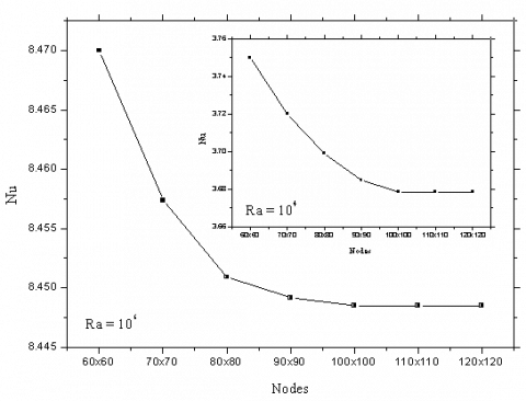
In order to determine an optimal grid for the present numerical predictions, a grid independence study is conducted. The mean Nusselt number was calculated for several mesh distributions, ranging from 60x60 to 120x120, as displayed in Figure 4. It can be observed that a 90x90 uniform grid is adequate for a grid independent solution. However, to minimize the discretization errors in the numerical simulations, a fine structured mesh of 100x100 is used to avoid round-off error for all other calculations in this study.
Figure 4. Average Nusselt number for different uniform grids; Yp = 0.15; φAl2O3 = 0.10
The presented results are generated for different pertinent dimensionless groups as: the Rayleigh number (104 ≤ Ra ≤ 106) and the solid volume fraction (0% to 10%). The default parameters are assigned to the heaters’ width value, (w = 0.10), and the Prandtl number, (Pr = 6.2). Three different types of nanoparticles are investigated as: Ag, CuO and Al2O3. The predicted hydrodynamic and thermal fields’ variables are presented through the streamlines, the isotherms, and the corresponding velocity profiles. The average Nusselt number is also represented in order to supply useful information about the influence of each parameter, quoted above, on the mean transfer enhancement.
The present study is carried out in two phases: in the first one, and for each nanofluid, the effects of both; Rayleigh number and solid volume fraction on the heat transfer performance is investigated, when the heaters location Yp is fixed at 0.15 and 0.75, respectively. In the second part, calculations are performed for a wide range of the heaters position: 0.15 ≤ Yp ≤ 0.75.
5.1 Rayleigh number & solid volume fraction
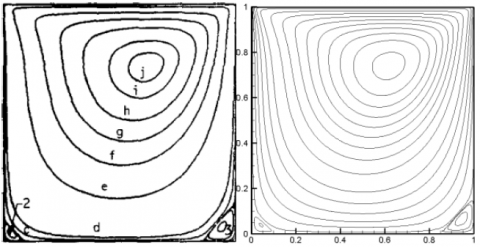
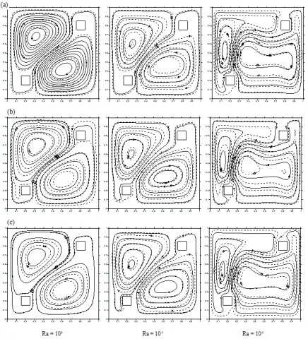
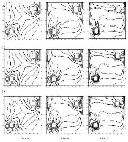
With each value of the Rayleigh number Ra, the streamlines and the isotherm plots of the (Ag, CuO or Al2O3)-water nanofluid with a volume fraction φ = 0.10 as well as the base fluid, (φ = 0), are shown in Figure 5. The related stream functions values are displayed in Table 3.
In the absence of the nanoparticles, φ = 0, and with a low value of the Rayleigh number, (which means that conduction heat transfer regime is dominant), the streamlines show two counter-rotating eddies established in the enclosure.
By increasing the Rayleigh number, the left counter-clockwise cell gets slighter whereas the streamlines become more packed adjacent to the cold wall, transporting the cold liquid towards the bottom. As Ra = 106, the convection mechanism becomes more pronounced and then, the right cell gets larger near the bottom wall indicating consequently, the strength motion of the cold liquid in this area. The same phenomenon occurs nearer the opposite wall where the left cell gets larger next to the top portion of the enclosure.
In the presence of the nanoparticles, the fluid motion is better than that of the pure fluid. In other words, the velocity components of nanofluids rise as the fluid’s energy transport increases with the increase nanoparticles volume fraction. The increase in the Rayleigh number adds to the flow strength which causes, in turn, the rise in the tendency of the cell to grow.
Regarding the thermal plots in Figure 5, for a Rayleigh number equals to 104, the isotherms are uniformly distributed inside de square, revealing a dominated-conduction heat transfer regime. As the Rayleigh number increases over than 104, the natural convection effect turns out to be dominant and then, the isotherms are distributed in a stratified manner with a horizontal profile in the middle of the enclosure, whereas thin thermal boundary layers are shaped around the heaters as well as along the side cold walls, indicating a large temperature gradient along these surfaces.
Table 3. Stream-function values for various Rayleigh number and different type of nanoparticles
|
|
φ = 0 |
φ = 0.10 |
||||||
|
Ra |
Pure water |
Ag |
CuO |
Al2O3 |
||||
|
|
Ymin |
Ymax |
Ymin |
Ymax |
Ymin |
Ymax |
Ymin |
Ymax |
|
104 |
-2.16 |
2.12 |
-3.17 |
3.12 |
-2.61 |
2.51 |
-2.23 |
2.20 |
|
105 |
-8.55 |
9.20 |
-12.30 |
13.05 |
-10.89 |
11.53 |
-10.00 |
10.56 |
|
106 |
-19.69 |
20.41 |
-27.75 |
28.93 |
-26.05 |
26.46 |
-25.09 |
25.46 |
Figure 7. Mean Nusselt number with the nanoparticles volume fraction for various values of the Rayleigh number
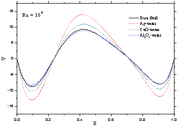
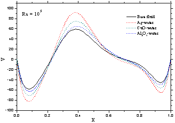
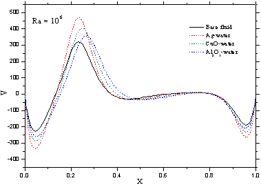
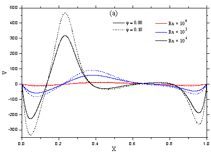
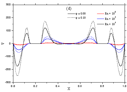
Figure 6 illustrates the vertical velocity component profiles (V-velocity) along the horizontal mid-plane of the cavity for the inspected types of the nanofluids. The examination of the magnitude of the vertical velocity component for different values of Ra confirms the weakness of the rotating eddies, previously observed in the streamlines, for a low Rayleigh number. Besides, the vertical velocity profiles verify the existence of a clockwise circulating cell at the right cavity side and an anti-clockwise circulating cell at the opposite side. The increase of the magnitude of the V-velocity with the increasing Rayleigh number indicates strong buoyant flows within the enclosure. The heat transfer mechanism is, therefore, expected to be due to convection while conduction is responsible for the heat transfer at low Rayleigh numbers.
It is important to denote here that, the negative velocity values illustrate the downward motion of the cold fluid nearer the side walls, and setting the heaters inside the enclosure as shown in Fig. 1 makes the cold fluid velocity greater on the left side compared to the right one.
Due to the nanoparticles thermo-physical properties at φ = 0.10, the nanofluids are associated with a higher absolute magnitude of the velocity compared to that of the pure water. The main fluid motion is noted with Ag-water nanofluid compared to CuO or Al2O3-water nanofluids.
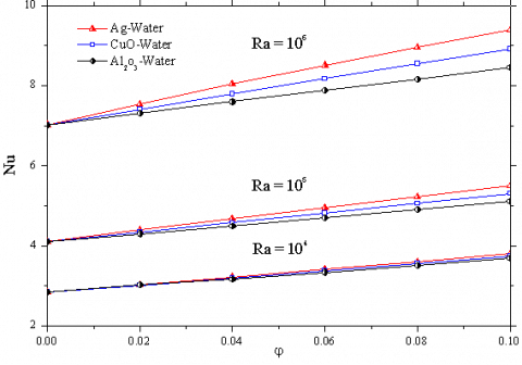
Figure 7 displays the mean Nusselt number calculated along the cavity sides with respect to the solid volume fraction at various values of the Rayleigh number. In general, the mean Nusselt number is an increasing function of the Rayleigh number as the convective regime becomes dominates and increases with the increase of the nanoparticles volume fraction, due to the improvement of the fluid thermal conductivity. A maximum heat transfer enhancement is computed with the Ag-water nanofluid compared to the CuO-water and Al2O3-water nanofluids.
Figure 5. Streamlines and isotherms plots for different values of the Rayleigh number, [ _ _ _ φ = 0.10, −−− base fluid].(a) Ag-water nanofluid. (b) CuO-water nanofluid. (c) Al2O3-water nanofluid
Figure 6. Effect of both the Rayleigh number and the types of nanoparticles on the vertical velocity profiles at Yp = 0.15; [ _ _ _ φ = 0.10, −−− base fluid]
5.2 Heaters position YP
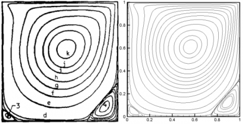
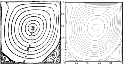
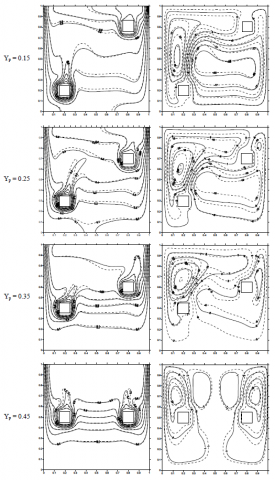
In this section, the heaters position Yp is ranging from 0.15 to 0.75. The main circulation cells as well as the isotherm plots of the Ag-water nanofluid, at Ra = 106, are presented in Figure. 8 for two different solid volume fractions such 0 and 0.10. Due to the symmetrical plan located at Yp = 0.50, the results are presented between 0.15 and 0.45.
Compared to the plots of the section before, Figure. 5(a), the proposed dispositions of the heaters affect the nanofluid flow motion. For Ra = 106 and when the distance wall-partition is about 0.15, two asymmetrical counter-rotating cells are formed inside the enclosure, whereas no secondary vortices appear. By increasing the distance wall-partition, the weak cell (located at the left side of the enclosure) enlarges to be identical to the right one. As a result, two symmetrical counter-rotating cells are observed and two secondary vortices grow between the primary ones due to the fluid motion.
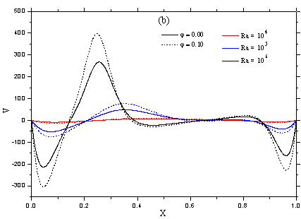
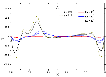
Figure 9 illustrates the vertical velocity profiles along the horizontal mid-plane of the enclosure for different distances Yp. As it is expected, the examination of the magnitude of the V-velocity at Yp = 0.45 confirms the symmetry of the primary rotating cells, previously observed in analyzing streamlines. In the same way as before, by using Ag nanoparticles (with φ = 0.10), the absolute magnitude of the velocity becomes higher.
The isotherms for each distance Yp are adjusted according to the presented streamlines. Once again, the clustering of these latter towards the heaters and the side walls reveals the high temperature gradient and the development of thin boundary layers nearer these surfaces.
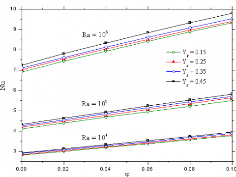
The effect of Yp on the mean Nusselt number for different values of both; the nanofluid volume fraction and the Rayleigh number is displayed in Figure 10. As we can see, the increase in the heaters position Yp has no significant effect on the heat transfer enhancement as the mean Nusselt number occurs at Yp = 0.45 is found to be quietly over 8% to that calculated at 0.15
The analysis of nanofluids natural convection inside a square enclosure, including two heated square bodies mounted nearer the cold walls was numerically realized in this paper. Taking into account the effects of various parameters, such the Rayleigh number, the heaters vertical position, the nanoparticles category and their volume fraction, optimal conditions leading to better heat transfer within this kind of enclosures are expected. The results may resume as follows:
- For the investigated nanofluids, heat transfer is found as an increasing function of the Rayleigh number and the nanoparticles volume fraction.
- For fixed values of both: the Rayleigh number and the nanoparticles volume fraction, the maximum heat transfer enhancement is obtained with the Ag-water nanofluid compared to the CuO-water and the Al2O3-water nanofluids. Hence, the use of Ag nanoparticles is required.
- A further increase in the heaters distance Yp affects the nanofluid motion but it has no significant effect on heat transfer enhancement.
Figure 8. Streamlines and isotherm plots of the Ag-water nanofluid for different values of Yp ; [ _ _ _ φ = 0.10, −−− base fluid]
(a) Yp = 0.15
(b) Yp = 0.25
(c) Yp = 0.35
(d) Yp = 0.45
Figure 9. Vertical velocity profiles for different values of the Rayleigh number and the heaters vertical position, [ _ _ _ φAg = 0.10, _______ base fluid]
Figure 10. Effect of the heaters position on the mean Nusselt number for various values of Ra and φAg
|
Cp |
Specific heat at constant pressure, J.kg-1. K-1 |
|
|
g |
Gravitational acceleration, m.s-2 |
|
|
H |
Cavity height, m |
|
|
k |
Thermal conductivity, W. m-1. K-1 |
|
|
Nu |
Average Nusselt number |
|
|
p* |
Pressure, Pa |
|
|
P |
Dimensionless pressure, = p* H2/ ρnf αf2 |
|
|
Pr |
Prandtl number |
|
|
Ra |
Rayleigh number |
|
|
T |
Dimensional temperature, K |
|
|
u, v |
Velocity components, m. s-1 |
|
|
U, V |
Dimensionless velocity components, = u (or v) H / αf |
|
|
W |
Heater’ width, m |
|
|
x, y |
Cartesian coordinates, m |
|
|
X, Y |
Dimensionless Cartesian coordinates, = x (or y) / H |
|
|
Xp |
Heater’ distance from the cold wall |
|
|
Yp |
Heater’ distance from the bottom wall |
|
|
Greek Symbols |
||
|
a |
Thermal diffusivity, m2. s-1 |
|
|
b |
Thermal expansion coefficient, K-1 |
|
|
q |
Dimensionless temperature, = (T-Tc)/(Th-Tc) |
|
|
μ |
Dynamic viscosity, kg. m-1. s-1 |
|
|
r |
Density, kg. m-3 |
|
|
φ |
Solid volume fraction |
|
|
Y |
Stream function |
|
|
Subscripts |
||
|
c |
Cold |
|
|
h |
Hot |
|
|
f |
Fluid (pure water) |
|
|
nf |
Nanofluid |
|
|
s |
Solid particles |
|
[1] Choi S.U.S. (1995). Enhancing thermal conductivity of fluids with nanoparticles, ASME Publications-FED, Vol. 231, pp. 99-105.
[2] Wang X., Xu X., Choi S.U.S. (1999). Thermal conductivity of nanoparticles fluid mixture, J. Thermo. Heat Transfer, Vol. 13-4, pp. 474-480. DOI. 10.2514/2.6486
[3] Jou R.Y., Tzeng S.C. (2006). Numerical research of nature convective heat transfer enhancement filled with nanofluids in rectangular enclosures, Int. Communi. Heat Mass Transfer, Vol. 33, pp. 727-736. DOI: 10.1016/j.icheatmasstransfer.2006.02.016
[4] Santra A.K., Sen S., Chakraborty N. (2008). Study of heat transfer augmentation in a differentially heated square cavity using copper-water nanofluid, Int. J. Thermal Sci., Vol. 47, pp. 1113-1122. DOI: 10.1016/j.ijthermalsci.2007.10.005
[5] Santra A.K., Sen S., Chakraborty N. (2009). Study of heat transfer due to laminar flow of copper–water nanofluid through two isothermally heated parallel plates, Int. J. Thermal Sci., Vol. 48, pp. 391-400. DOI: 10.1016/j.ijthermalsci.2008.10.004
[6] Lelea D. (2011). The performance evaluation of Al2O3-water nanofluid flow and heat transfer in microchannel heat sinks, Int. J. Heat Mass Transfer, Vol. 54, pp. 3891-3899. DOI: 10.1016/j.ijheatmasstransfer.2011.04.038
[7] Moraveji M.K., Darabi M., Haddad S.M.H., Davarnejad R. (2011). Modeling of convective heat transfer of a nanofluid in the developing region of tube flow with computational fluid dynamics, Int. Communic. Heat Mass Transfer, Vol. 38, pp. 1291-1295. DOI: 10.1016/j.icheatmasstransfer.2011.06.011
[8] Mokhtari R.M., Akbarinia A., Shariat M., Talebi F., Laur R. (2011). Two phase mixed convection Al2O3-water nanofluid flow in an annulus, Int. J. Multiphase Flow, Vol. 37, pp. 585-595. DOI: 10.1016/j.ijmultiphaseflow.2011.03.008
[9] Cho C.C., Chen C.L., Chen C.K. (2012). Natural convection heat transfer performance in complex-wavy-wall enclosed cavity filled with nanofluid, Int. J. Thermal Sci., Vol. 60, pp. 255-263. DOI: 10.1016/j.ijthermalsci.2012.05.001
[10] Ghasemi B., Aminossadati S.M. (2009). Natural convection heat transfer in an inclined enclosure filled with a water-CuO nanofluid, Numer. Heat Transfer Part A Appli., Vol. 55, pp. 807-823. DOI: 10.1080/10407780902864623
[11] Ogut E.B. (2010). Heat transfer of water-based nanofluids with natural convection in an inclined square enclosure, J. Thermal Sci. Techno., Vol. 30, pp. 23-33. DOI: 10.1016/j.ijthermalsci.2009.03.014
[12] Kahveci K. (2010). Buoyancy driven heat transfer of nanofluids in a tilted enclosure, J. Heat Transfer., Vol. 132, pp. 1-12. DOI: 10.1115/1.4000744
[13] Khanafer K., Vafai K., Lightstone M. (2003). Buoyancy-driven heat transfer enhancement in a two-dimensional enclosure utilizing nanofluids, Int. J. Heat Mass Transfer, Vol. 6, pp. 3639-3653. DOI: 10.1016/S0017-9310(03)00156-X
[14] Tiwari R.K., Das M.K. (2007). Heat transfer augmentation in a two-sided lid-driven differentially heated square cavity utilizing nanofluids, Int. J. Heat Mass Transfer, Vol. 50, pp. 2002-2018. DOI: 10.1016/j.ijheatmasstransfer.2006.09.034
[15] Oztop H.F., Abu-Nada E. (2008). Numerical study of natural convection in partially heated rectangular enclosures filled with nanofluids, Int. J. Heat Fluid Flow, Vol. 29, pp. 1326-1336. DOI: 10.1016/j.ijheatfluidflow.2008.04.009
[16] Muthtamilselvan M., Kandaswamy P., Lee J. (2010). Heat transfer enhancement of copper-water nanofluids in a lid-driven enclosure, Communi. in Nonlinear Sci. Numer. Simu., Vol. 15, pp. 1501-1510. DOI: 10.1016/j.cnsns.2009.06.015
[17] Mahmoudi M. (2011). Numerical simulation of free convection of nanofluid in a square cavity with an inside heater, Int. J. Thermal Sci., Vol. 50, pp. 2161-2175. DOI: 10.1016/j.ijthermalsci.2011.05.008
[18] Mahmoodi M., Sebdani S.M. (2012). Natural convection in a square cavity containing a nanofluid and an adiabatic square block at the center, Super. Lattices and Microstructures, Vol. 52, pp. 261-275. DOI: 10.1016/j.spmi.2012.05.007.
[19] Bejan A. (2004). Convection Heat Transfer, John Wiley & Sons, Inc., Hoboken, New jersey, USA. DOI. 10.1002/9781118671627
[20] Brinkman H.C. (1952). The viscosity of concentrated suspensions and solutions, J. Chemical Physics, Vol. 20, pp. 571-581. DOI: 10.1063/1.1700493
[21] Maxwell J.C. (1873). A Treatise on Electricity and Magnetism, Vol. II, Cambridge University Press, UK, p. 54. DOI. 10.1017/CBO9780511709340
[22] Patankar S.V. (1980). Numerical Heat Transfer and Fluid Flow, Hemisphere Publishing Corporating, Taylor and Francis Group, New York.
[23] Ghia U., Ghia K.N., Shin C.T. (1982) High-resolutions for incompressible flow using the Navier-stokes equations and a multigrid method, Journal of Computational Physics, Vol. 48, pp. 387-411. DOI. 10.1016/0021-9991(82)90058-4
[24] Arefmanesh A., Amini M., Mahmoodi M., Najafi M. (2012). Buoyancy-driven heat transfer analysis in two-square duct annuli filled with a nanofluid, Europ. J. Mech. B-Fluids, Vol. 33, pp. 95-104. DOI: 10.1016/j.euromechflu.2011.11.004