OPEN ACCESS
Heat transfer in a channel in presence of a hexagonal cylinder has been numerically investigated. The flow analysis on hexagonal cylinder surrounding laminar and turbulent regime is done with the Reynolds number ranging from 100-50000 and turbulence intensities from 5% to 50%. Air being the flowing medium is considered to have constant Prandtl number. The problem is simplified to a three-dimensional approach. Continuity, momentum, and energy equations are used for the solution of the governing equations. Transition SST Model is used to perform computation of steady variants. The analysis results are verified with correlations and it is being observed that they are similar to each other. This work indicates that SST Model can connect all flow regimes for forecasting the heat transfer with almost no effort.
cylinder, hexagonal, forced convection, turbulent flow, SST model, heat transfer
The flow around bluff cylinders has been widely studied due to its theoretical and practical importance in engineering and scientific relevance in thermal engineering and fluid mechanics. The fluid flow is external when it is flowing over the surface and internal flow when it is flowing in the conduit. The characteristic of external flow is different from internal flow. Circular-cylindrical structures are used for various devices in mechanical, civil and other engineering fields. In the designing of heat exchangers for locomotive, cooling system for nuclear power plants, offshore structures, buildings, chimneys cylinder-like structures are found both in alone and in a group. Air and water as the flowing medium are used power lines, grids, screens, and cables. The flow around circular cylinders show various important physical phenomena, such as separation of flow, vortex shedding and also the shifting of flow from laminar to turbulence. The shape of the bodies determines the form of flow and the energy transformation and flow characteristics. Thus, designer should be aware of developing the correct shape and dimension of the body. Any deviation from the proper shape or dimension may result in a loss of the efficiency of flow or heat exchange process. Motlagh and Hashemabadi [1] performed a two and three-dimensional CFD modelling of heat transfer from discrete circular cylindrical particles in four different cases. These are infinite cylinder in cross-flow, cross-flow on finite cylinder with different aspect ratio in a rectangular duct; axial-flow on finite cylinder and axial-flow on finite cylinder with upstream turbulence have been inspected with the commercial CFD software. The standard
κ–ɛ turbulence model is used to calculate eddy viscosity of flow neglecting all body forces. CFD simulations and experimental results are properly arranged for obtaining local and overall heat transfer coefficient. Kondjoyan and Daudin [2] have shown the effect of free stream turbulence intensity on heat and mass transfer at a surface of circular cylinder and an elliptical cylinder. The cross flow around circular cylinder is observed and is found to have turbulence intensity ranging from 1.5 to 40% and of Reynolds number ranging from 3000 to 40000 on transfer coefficients. The effect of turbulence intensity is important as the influence of velocity and it seemed to be independent of the pressure gradient and of the degree of turbulence isotropy.
It is also observed that the air flow properties affect the heat transfer more than the cylinder axis ratio does. Their work also approves that the local transfer coefficient is much higher at the stagnation point of a circular cylinder than elsewhere at the surface. Sanitjai and Goldstein [3] study the Local and average heat transfer by forced convection from a circular cylinder. A Reynolds number ranging from 2000 to 90000 and Prandtl number from 0.7 to 176 has been considered. Their results are interesting for subcritical flow. Their results are interesting for subcritical flow. The local heat transfer measurement directs three flow regions including laminar boundary layer region, reattachment of shear layer region and periodic vortex flow region. The average heat transfer is calculated and interrelated with the Reynolds number and the Prandtl number in each flow region. The Nusselt number is also a function of Reynolds number and Prandtl number in each flow region. Some more vortex generators have been intensively investigated recently [4-18]. The focus of the present analysis is on the transport phenomena in hexagonal cylinder. The presented work provides a standard test for CFD simulations of heat transfer from hexagonal cylinder and confirmed with the correlations for allowing further study of heat transfer on more complex geometries.
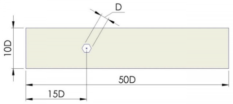
The forced convection cross flow around a hexagonal cylinder is considered in the present work. H=10D has been used as the ratio of the width of the cylinder to the vertical distance between the upper and lower walls. The problem is considered to be three-dimensional. Figure 1 shows the computational domain where D is the diameter of the cylinder. The working fluid is air having Prandtl number 0.71.
The grid selected in this work, has 22542 nodes; and it is selected by following Richardson extrapolation method. The present grid result contradicts by 4.52% from grid independent value. Grids are generated on the CAD drawing, using GAMBIT, solver fluent 16.2 for proper simulation and analysis. Structured grids are generated as shown in Figure 2.
Fluid approaches the plate with an inlet velocity of $U \infty$ and the temperature of the inlet fluid is $T \infty$. The cylinder constant surface temperature is maintained at $T_{S}$ = 500k. Air is considered as the working fluid with constant physical properties (Pr=0.71) with an inlet temperature of 300k. The domain size is fixed and the fluid properties are also considered to be constant. Thus, the variation of Reynolds number is done by changing the inlet velocity.
The three dimensional governing equations of continuity, momentum and energy equations are solved using Transient SST model modified and proposed by Abraham et. al. [19]. Ansys Fluent 16.2 is used to solve the following governing equations.
$\frac{\partial u_{i}}{\partial x_{i}}=0$ (1)
$\rho\left(u_{i} \frac{\partial u_{j}}{\partial x_{i}}\right)=-\frac{\partial p}{\partial x_{i}}+\frac{\partial}{\partial x_{i}}\left(\left(\mu+\mu_{t u r b}\right) \frac{\partial u_{i}}{\partial x_{i}}\right), j=1,2,3$ (2)
$\left(u_{i} \frac{\partial \Theta}{\partial x_{i}}\right)=\frac{\partial}{\partial x_{i}}\left(\left(\alpha+\frac{v_{t u r b}}{\operatorname{Pr}_{t u r b}}\right) \frac{\partial \Theta}{\partial x_{i}}\right)$ (3)
$\frac{\partial\left(\rho u_{i} \kappa\right)}{\partial x_{i}}=\gamma \cdot P_{\kappa}-\beta_{1} \rho \kappa \omega+\frac{\partial}{\partial x_{i}}\left(\left(\mu+\frac{\mu_{t u r b}}{\sigma_{\kappa}}\right) \frac{\partial \kappa}{\partial x_{i}}\right)$ (4)
$\frac{\partial\left(\rho u_{i} \omega\right)}{\partial x_{i}}=A \rho S^{2}-\beta_{2} \rho \omega^{2}+\frac{\partial}{\partial x_{i}}\left(\left(\mu+\frac{\mu_{t u r b}}{\sigma_{\omega}}\right) \frac{\partial \omega}{\partial x_{i}}\right)+2\left(1-F_{1}\right) \rho \frac{1}{\sigma_{\omega 2} \omega} \frac{\partial \kappa}{\partial x_{i}} \frac{\partial \omega}{\partial x_{i}}$ (5)
where
$\mu_{t u r b}=\frac{a \rho \kappa}{\max \left(a \omega, S F_{2}\right)}$ (6)
$\frac{\partial(\rho \gamma)}{\partial t}+\frac{\partial\left(\rho u_{i} \gamma\right)}{\partial x_{i}}=P_{\gamma, 1}-E_{\gamma, 1}+P_{\gamma, 2}-E_{\gamma, 2}+\frac{\partial}{\partial x_{i}}\left(\left(\mu+\frac{\mu_{t u r b}}{\sigma_{\gamma}}\right) \frac{\partial \gamma}{\partial x_{i}}\right)$ (7)
$\frac{\partial(\rho \Pi)}{\partial t}+\frac{\partial\left(\rho u_{i} \Pi\right)}{\partial x_{i}}=P_{\Pi, t}+\frac{\partial}{\partial x_{i}}\left(\sigma_{\Pi, t}\left(\mu+\mu_{t u r b}\right) \frac{\partial \Pi}{\partial x_{i}}\right)$ (8)
CFD fluent 16.2 are used for solving the governing equations. Second order accurate QUICK scheme discretized the momentum equation used for achieving desired level of accuracy. Third-order MUSCL is used for solving the energy equation. The scaled residual value below 10-5 for momentum and 10-8 for energy equations converged the solutions. The interpolation of the temperature gradients used the third order accurate scheme and the gradients for intermittency (γ), turbulent kinetic energy, specific dissipation rate, and momentum thickness used second order accurate upwind scheme. The discretized equations are then linear using an implicit scheme and solved iteratively.
Figure 1. Computational domain
Figure 2. Meshing near the cylinder wall
The results obtained after the simulation performed with the several Reynolds numbers are discussed in this section. The analysis is conducted for Reynolds numbers ranging from 100 50,000. The variation of average Nusselt number with the increase of Reynolds number at particular turbulence intensity is examined and the increase in heat transfer coefficient with the increase in turbulence intensity is conveyed. The turbulence intensity varies from 5% to 50%.
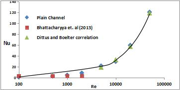
Figure 3 shows the variation of Nusselt number with Reynolds number. The CFD simulation is performed for Reynolds number of 100 to 50,000 and the curve shows good agreements with the correlation.
Figure 3. Variation of Nusselt number with Reynolds number
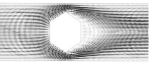
The flow structure in presence of hexagonal cylinder could be easily detected by observing at the velocity vector plots at Figure 4 here the velocity field around the hexagonal cylinder is presented. It can be seen that the flow stream divides itself in two streams as it hits the hexagonal cylinder and combines after the hexagonal cylinder.
Figure 4. Velocity vectors around the hexagonal cylinder
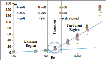
The transformation of flow field from laminar zone to turbulence zone can be visualized from Figure 5. In laminar zone, the rate of increase in Nusselt number is steady where as in turbulence zone this rate of increase is very high. From the curve, it is clear that for external cross flow over a hexagonal cylinder the transition zone is around 2000. The variation of Nusselt number with Reyonlds number for different turbulence intensity is shown in Figure 5. The increase in Nusselt number with increase in Reynolds number for the turbulence intensity of 5%, 10%, 15%, 20%, 25%, 30%, 40% and 50% has been recorded in this present work. From the Figure 5 it is clear that for low value of Reynolds number the heat transfer rate is not much enhanced by the turbulence intensity but when the value of Reynolds number is higher than 10,000 the heat transfer coefficient is increased at a higher rate. The Nusselt number is almost same for Reynolds number up to 1,000. But beyond this value of Re, Nusselt number increases eminently with increasing turbulence intensity.
Figure 5. Effect of turbulence intensity on Nusselt number
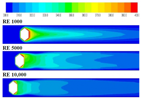
The temperature contours near the cylinder wall are shown in Figure 6. From the figure, the effect of cylinder temperature on the flow field is observed. A relatively lower temperature zone is established in the wake of the cylinder. This may be due to the fact that the time available for the fluid to extract heat is reduced at higher Reynolds number.
The turbulent kinetic energy contour plot is presented in Figure 7. The hexagonal cylinder is found to produce a highly turbulent filed as replicated in the high values of turbulent kinetic energy. Two sectors of high turbulence correspond to the two vortices also observed in Figure 7.
Figure 6 Temperature contour near cylinder wall at different Reynolds number
Figure 7. Turbulent kinetic energy contour near cylinder wall at Re 10,000
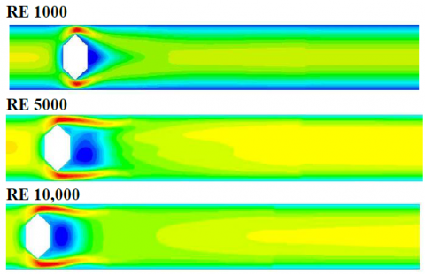
The flow arrangement is represented by axial velocity contours around the long expanded hexagonal cylinder in steady regimes is shown in Figure 8. It is a group of constant velocity lines in the field of present study which help in the analysis of fluid flow appearances and also in classifying the nature of flow.
Figure 8. Axial velocity contour near cylinder wall at different Reynolds number
In this work, a hexagonal cylinder in a square domain has been simulated. The work forecasts the steady, three-dimensional incompressible flow as well as the thermal behaviour for a cross flow past the hexagonal cylinder numerically. It is found that Reynolds number has a important role on area weighted average of Nusselt number. Nusselt number increases with the increase Reynolds number increases and turbulence intensity. Initially the value of Pressure coefficient decreases and then it increases with increase in Reynolds number. Prediction of transition from laminar to turbulent regime is done. By drawing tangents at the laminar data ranges and at the end turbulent regime, we can recognize the transition zone. The results from purely laminar and those from turbulent model agree well with the results from transition SST model.
[1] Ahmadi M.A.H., Hashemabadi S.H. (2008). CFD based evaluation of heat transfer coefficient from cylindrical particles, International Communications in Heat and Mass Transfer, Vol. 12, No. 35, pp. 674-680.
[2] Kondjoyan A., Daudin J.D. (1995). Effects of free stream turbulence intensity on heat and mass transfers at the surface of a circular cylinder and an elliptical cylinder, axis ratio 4, Int. J. Heat Mass Transfer, Vol. 10, No. 38, pp. 1735-1749.
[3] Sanitjai S., Goldstein R.J. (2004). Forced convection heat transfer from a circular cylinder in cross flow to air and liquids, International Journal of Heat and Mass Transfer, Vol. 12, No. 47, pp. 4795-4805.
[4] Bhattacharyya S., Saha S.K. (2012). Thermohydraulics of laminar flow through a circular tube having integral helical rib roughness and fitted with centre-cleared twisted-tape, Experimental Thermal and Fluid Science, Vol. 42, pp. 154-162.
[5] Bhattacharyya S., Saha S., Saha S.K. (2013). Laminar flow heat transfer enhancement in a circular tube having integral transverse rib roughness and fitted with centre-cleared twisted-tape, Experimental Thermal and Fluid Science, Vol. 44, pp. 727-735.
[6] Saha S.K., Bhattacharyya S., Pal P.K. (2012). Thermohydraulics of laminar flow of viscous oil through a circular tube having integral axial rib roughness and fitted with center-cleared twisted-tape, Experimental Thermal and Fluid Science, Vol. 41, pp. 121-129.
[7] Saha S.K., Bhattacharyya S., Dayanidhi G.L. (2012). Enhancement of heat transfer of laminar flow of viscous oil through a circular tube having integral axial rib roughness and fitted with helical screw-tape inserts, Heat Transfer Research, Vol. 43, No. 3, pp. 207-227.
[8] Bhattacharyya S., Chattopadhyay H. (2015). Computational of studies of heat transfer enhancement in turbulent channel flow with twisted strip inserts, In: Proceedings of CHT-15, ICHMT International Symposium on Advances in Computational Heat Transfer.
[9] Bhattacharyya S., Roy A., Bhattacharyya A., Dey K., Seth D. (2015). Computational heat transfer analysis of a counter-flow heat exchanger with fins, Proceedings of Recent Developments in Mechanical Engineering.
[10] Bhattacharyya S., Chattopadhyay H., Saha S.K. (2014). Numerical study on heat transfer enhancement of laminar flow through a circular tube with artificial rib roughness, J. Refrig, Air Conditioning, Heat. Ventilation, Vol. 1, No. 3, pp. 14-19.
[11] Bhattacharyya S., Roy A., Chattopadhyay H., Rakshit A. (2016). A numerical investigation based on heat transfer and fluid flow characteristics of air in a circular tube heat exchanger with inclined ribs, Proceedings of ICACE 2015, Recent Advances in Chemical Engineering, pp. 11-20. DOI: 10.1007/978-981-10-1633-2_2
[12] Bhattacharyya S., Chattopadhyay H., Bandyopadhyay S. (2016). Numerical study on heat transfer enhancement through a circular duct fitted with centre-trimmed twisted tape, International Journal of Heat and Technology, Vol. 34, No. 3, pp. 401-406.
[13] Bhattacharyya S., Chattopadhyay H., Roy A., Rakshit A., Chowdhury I.R. (2016). Thermohydraulic transport characteristics of micro mixer in micro channel, Proceedings of ICACE 2015, Recent Advances in Chemical Engineering, pp. 29-39. DOI: 10.1007/978-981-10-1633-2_4
[14] Bhattacharyya S., Chattopadhyay H., Pal T.K., Roy A., Numerical investigation of thermohydraulics performance in elliptical twisted duct heat exchanger, CAD/CAM, Robotics and Factories of the Future Part of the series Lecture Notes in Mechanical Engineering, pp, 839-849. DOI: 10.1007/978-81-322-2740-3_81
[15] Bhattacharyya S., Chattopadhyay H., Benim A.C. (2016). Heat transfer enhancement of laminar flow of ethylene glycol through a square channel fitted with angular cut wavy strip, Procedia Engineering, Vol. 157, pp. 19-28. DOI: 10.1016/j.proeng.2016.08.333
[16] Bhattacharyya S., Chattopadhyay H., Bandyopadhyay S., Roy S., Pal A., Bhattacharjee S. (2016). Experimental investigation on heat transfer enhancement by swirl generators in a solar air heater duct, International Journal of Heat and Technology, Vol. 34, No. 2, pp. 191-196. DOI: 10.18280/ijht.340206
[17] Bhattacharyya S., Chattopadhyay H., Pal A., Bandyopadhyay S., Roy S. (2015). Numerical simulation of fluid flow and heat transfer enhancement in a circular wavy channel, Journal of Thermal Engineering and Applications, Vol. 2, No. 2, pp. 28-35.
[18] Bhattacharyya S., Chattopadhyay H., Benim A.C., Simulation on heat transfer enhancement in tube flow with twisted tape insert, PCFD, published in Press.
[19] Abraham A.P., Sparrow E.M., Tong J.C.K. (2009). Heat transfer in all pipe flow regimes: laminar, transitional/intermittent, and turbulent, Int. J. Heat and Mass Transfer, No. 52, pp. 557-563.