OPEN ACCESS
Swirling effect of impinging jet on turbulent convective heat transfer over the hot plate containing obstacles was studied numerically. To create the swirling flow, input the twisted tape in the nozzle. The twisted number changes are 0 (straight tape), 5, 8, 10 and 12. Three arrangements of obstacles were used. Reynolds number equals to 20,000 and the distance ratios of impinging jet to the impingement plate (b/D) are 2 and 4. The results show that in without obstacle mode in b/D=2, the highest heat-transfer rate happens to use the twisted tape with 12 twists. At b/D=4, by increasing the twist number, the heat transfer decreases. By 12 twists for the impingement plate with one obstacle in b/D=2 the average Nusselt number increases 29 percent higher than the conventional impinging jet (CIJ) and in b/D=4, the heat transfer with swirling flow would be more than CIJ. For impingement plate with three and four obstacles, the swirling flow does not have sensible effect on the heat transfer.
Heat Transfer, Impinging Jet, Turbulent Flow, Swirling Flow
Impinging jet is one active way to improve the heat-transfer. In impinging jet, liquid or gas stream directly impacts the impingement plate, which causes to transfer a lot of heat energy between fluid and impingement plate. Because of its high rate of heat transfer, this method is widely used in many fields of engineering applications. Some of these applications are cooling of turbine blades and electronic components, heat treating, tempering of glass, drying of papers and food products.
the effect of some parameters to improve the heat transfer in impinging jet were investigated such as distance from the nozzle to impingement plate, jet velocity (changing Re), jet array assembly (in multiple jet), nozzle and plate shapes, swirling flow and etc. Jambunathan et al. [1] wrote a review paper about the existing experimental data of heat transfer in circular impinging jet (CIJ). In this study the effect of nozzle distance to plate, Re number were investigated. Some emprical correlations were repoted aslo.Their studied shows that the b/D greater than 12 does not have sensible effect on heat transfer from the plate. Lytle and Web [2] experimentally investigated the heat transfer charactristics of air impinging jet from the plate with low distance (b/D<1) using infrared thermal imaging technique. Their results show the power law relationship between Nusselt number and distance between nozzle and plate.
Researchers tried to find ways to improve heat transfer in impinging jet. One of the parameters to enhance heat transfer is swirling impinging jet instead of CIJ. The first study on the swirling flow in impinging jet was done by Ward and Mahmood [2] in 1982. They found that a swirling impinging jet (SIJ) has more uniform radial distribution of velocity than CIJ, and they showed that by increasing of the nozzle to plate distance (b), the Nusselt number decreases.
The distance from the nozzle to the plate is another parameter that can effect on heat transfer rate and on the distribution of the local heat transfer coefficient. Baughn and Shimizu [3] investigated on this parameter. They showed that maximum heat transfer in b/D=2, occurs at the stagnation region. Minimum amount of heat transfer occurs at r/D=1.3 and the second peak heat transfer at r/D=1.8. Ledezma et al. [4] numerically and experimentally investigated heat transfer in finned plate with impinging flow. They found an equation for optimum fin distances and the maximum thermal conductivity.
Behnia et al. [5] investigated heat transfer in impinging jet with k-ε and v2-f turbulence models. They showed that the v2-f model accurately predicts the results. Huang and El-Genk [6] used swirling impinging jet (SIJ) with swirl angles (θ=15 °, 30 ° and 45 °) and multi-channel impinging jets (MCIJ). They showed that the Nusselt number in SIJ is more than MCIJ and CIJ. Brignoni and Garimella [7] experimentally showed the optimization of confined impinging air jets used in conjunction with a pin-fin heat sink. Enhancement factors for the heat sink were evaluated. They expressed, both the average heat transfer coefficients and the thermal resistance for the heat sink as a function of a Reynolds number, an air flow rate, a pumping power, and a pressure drop, to assist in optimizing the jet impingement configuration for given design constraints. Maveety and Hendricks [8] investigated the effect of geometry, nozzle- plate distance, Material and Reynolds number in cooling hot finned plate by impinging jet. Their resuts show that the best result achieved when b/D is between 8 and 12 and Reynolds number between 40000 and 50000. Lee et al. [9] studied the effect of swirling on the local and average heat transfer distribution. They found that at the small nozzle to plate distance (b/D=2), swirling effect was considerable but at b/D>10, this effect almost was disappeared. Zuckerman and Lior [10] studied accuracy and the ability of different turbulence models in simulation of impinging jet. Their results show that v2-f turbulence model both in terms of accuracy and in terms of time spent, is more appropriate. Bakirci and Bilen [11] investigated the temperature distribution and the heat transfer rate of CIJ, SIJ and MCIJ. They used different swirl angles (θ= 0 °, 22.5 °, 41 °, and 50 °). According to their results, with increasing of swirl angle, the radial uniformity of the local and average Nusselt numbers was improved. They also showed that the best result was occur at θ=50 °and b/D=14. Yang et al. [12] demonstrated detailed annular impinging jet behaviors induced by a swirling motion. They reported that at a short and intermediate b/D, annular swirling jet provided non-uniform wall pressure and Nusselt number distributions on the impinged surface. Nanan et al. [13] experimentally investigated the effect of the twist ratio (y/W), jet-to-plate spacing (b/D), and jet Reynolds number on the local/average Nusselt number on the impingement plate. They showed that at the largest twist ratio, the smallest b/D, and the highest jet Reynolds number, the maximum local/average Nusselt number on the impingement plate was occurred. Nuntadusit et al. [14] studied the effect of the swirl number on the flow and heat transfer characteristics in an impinging jet on an impinged surface using straight and twisted tape inserts. They found that in y/w=3.64, the maximum heat transfer achieved. Salman et al. [15] investigated the effect of swirl intensity on heat transfer of SIJ at b/D=2. They used twisted tapes with three twist ratios (y/w=1.46, 1.95, and 2.44) and Reynolds numbers that varied from 4,000 to 16,000. Their results showed that with the twisted ratio equal with 2.44, uniformity of local heat transfer distribution on the surface was better than other cases. Sivakumar and Rajan [16] experimentally investigated heat-transfer in tube with twisted tape inserts. Their results showed that twisted tape enhances heat transfer and increase friction factor. Kaliakatsos et al. [17] numerically analyzed heat transfer, temperature, pressure and velocity at a pipe equipped with twisted tape. Recently Carlomagno and Ianiro [18] reviewed the submerged jet at the short distance of nozzle to plate. Amini et al. [19] investigated the twisted tape effect on impining jet cooling on the plate numerically. They found that swirling flow has positive effect on heat transfer at b/D= 6 and 8. In addition, they reportad that two nozzle have better performance in comparison with one nozzle in the same air flow rate.
Greco et al. [20] studied the behavior of impinging single and twin circular synthetic jets in phase opposition experimentally by using PIV. Tesarˇ et al. [21] experimantally controlled the impinging jet with fluidic signal technique. With this method, the heat transfer area which is cooling or heating by jet, increases sufficiently. Ahmed et al. [22] investigated the thermal and flow flieds behavier of swirling and non-swirling impining jet numerically and experimentally. Thery results show that impining distance is imprtant at heat trafsre rate from the plate at swirning jet flow.
Reviewing previous works in impinging jet shows that the simultaneous influence of swirling flow and obstacle on a plate, has not been investigated. In this paper, the effect of swirling flow on heat transfer in impinging jet is investigated on the plate with and wthouth the obstacles.
Governing equations for incompressible fluid, constant properties and steady condition are as following:
continuity:
$\frac{\partial {{u}_{i}}}{\partial {{x}_{i}}}=0$ (1)
where $u_i$ is the velocity component in each principal direction. Momentum and energy equations can be written as:
$\frac{\partial }{\partial {{x}_{j}}}({{u}_{i}}{{u}_{j}})=-\frac{1}{\rho }\frac{\partial p}{\partial {{x}_{i}}}+\frac{1}{\rho }\frac{\partial {{\tau }_{ij}}}{\partial {{x}_{j}}}+{{F}_{i}}$ (2)
${{\tau }_{ij}}=\mu \frac{\partial {{u}_{i}}}{\partial {{x}_{j}}}+{{\mu }_{t}}\left( \frac{\partial {{u}_{i}}}{\partial {{x}_{j}}}+\frac{\partial {{u}_{j}}}{\partial {{x}_{i}}} \right)-\frac{2}{3}k{{\delta }_{ij}}$
$({{u}_{i}}\frac{\partial T}{\partial {{x}_{i}}})=\frac{\partial }{\partial {{x}_{i}}}\left( {{\alpha }_{eff}}\frac{\partial T}{\partial {{x}_{i}}} \right),\,\,\,{{\alpha }_{eff}}=\alpha +{{\alpha }_{t}}\,\,,\,\,\,\,\,\,\,{{\alpha }_{t}}={{\Pr }_{t}}\,\times {{\nu }_{t}}\,\,\,$ (3)
where ${{\delta }_{ij}}$ is the Kronecker delta, Prt is turbulent Prandtl number that is equal to unity, ${{\nu }_{t}}$ is turbulent kinematic viscosity and ${{\alpha }_{t}}$ is turbulent thermal diffusivity.
In this study the v2-f model is used for turbulence modeling.
The turbulence kinetic energy equation (k):
$\frac{\partial }{\partial t}(\rho k)+\frac{\partial }{\partial {{x}_{i}}}\left( \rho k{{u}_{i}} \right)=p-\rho \varepsilon +\frac{\partial }{\partial {{x}_{j}}}{{\left[ \left( \mu +\frac{{{\mu }_{t}}}{{{\sigma }_{k}}} \right)\frac{\partial k}{\partial {{x}_{j}}} \right]}_{k}}$ (4)
Rate of dissipation ($\varepsilon $) equation:
$\frac{\partial }{\partial {{x}_{i}}}(\rho \varepsilon {{u}_{i}})=\frac{{{{{C}'}}_{\varepsilon 1}}P-{{C}_{\varepsilon 2}}\rho \varepsilon }{T}+\frac{\partial }{\partial {{x}_{j}}}\left[ \left( \mu +\frac{{{\mu }_{t}}}{{{\sigma }_{\varepsilon }}} \right)\frac{\partial \varepsilon }{\partial {{x}_{j}}} \right]$ (5)
The velocity variance scale (${{\bar{v}}^{2}}$) equation:
$\frac{\partial }{\partial {{x}_{i}}}(\rho {{\bar{v}}^{2}}{{u}_{i}})=\rho kf-6\rho {{\bar{v}}^{2}}\frac{\varepsilon }{k}+\frac{\partial }{\partial {{x}_{j}}}\left[ \left( \mu +\frac{{{\mu }_{t}}}{{{\sigma }_{k}}} \right)\frac{\partial {{{\bar{v}}}^{2}}}{\partial {{x}_{j}}} \right]$ (6)
The elliptic relaxation function (f) equation:
$f-{{L}^{2}}\frac{{{\partial }^{2}}f}{\partial x_{j}^{2}}=\left( {{C}_{1}}-1 \right)\frac{\frac{2}{3}-{{{\bar{v}}}^{2}}/k}{T}+{{C}_{2}}\frac{P}{\rho k}+\frac{5{{{\bar{v}}}^{2}}/k}{T}$ (7)
where
$P=2{{\mu }_{t}}{{S}^{2}},{{S}^{2}}\equiv {{S}_{ij}}{{S}_{ij}},{{S}_{ij}}=\frac{1}{2}\left( \frac{\partial {{u}_{i}}}{\partial {{x}_{j}}}+\frac{\partial {{u}_{j}}}{\partial {{x}_{i}}} \right)$ (8)
The turbulent time scale T, length scale L and the turbulent viscosity (${{\mu }_{t}}$) are defined by:
${T}'=\max \left[ \frac{k}{\varepsilon },6\sqrt{\frac{v}{\varepsilon }} \right]$ (9)
$T=\min \left[ {T}',\frac{\alpha }{\sqrt{3}}\frac{k}{{{{\bar{v}}}^{2}}{{C}_{\mu }}\sqrt{2{{S}^{2}}}} \right]$ (10)
${L}'=\min \left[ \frac{{{k}^{3/2}}}{\varepsilon }.\frac{1}{\sqrt{3}}\frac{{{k}^{3/2}}}{{{{\bar{v}}}^{2}}{{C}_{\mu }}\sqrt{2{{S}^{2}}}} \right]$ (11)
$L={{C}_{L}}\max \left[ {L}',{{C}_{\eta }}{{\left( \frac{{{v}^{3}}}{\varepsilon } \right)}^{1/4}} \right]$ (12)
${{\mu }_{t}}=\rho {{C}_{\mu }}{{\bar{v}}^{2}}T$ (13)
The constants of this model are:
$\alpha =0.6,{{C}_{1}}=1.4,{{C}_{2}}=0.3,{{C}_{\varepsilon 1}}=1.4,{{C}_{\varepsilon 2}}=1.9,{{C}_{\eta }}=70$ (14)
$\begin{align} & {{C}_{\mu }}=0.22,{{C}_{L}}=0.23,{{\sigma }_{k}}=1,{{\sigma }_{\varepsilon }}=1.3, \\ & {{{{C}'}}_{\varepsilon 1}}=\left( 1+0.045\sqrt{k/{{{\bar{v}}}^{2}}} \right) \\\end{align}$ (15)
The Commercial software, Fluent 14.5 [23] base on FVM (Finite Volume Method), was used to simulate heat transfer in steady impinging jet. The SIMPLE algorithm for pressure-velocity coupling and second-order upwind scheme for the energy and momentum equations was used. For equations, including continuity, momentum, turbulence kinetic energy and turbulence specific dissipation rate, residuals are 10 -4 and for energy equation, is 10 -7. Default Fluent relaxation factor is used.
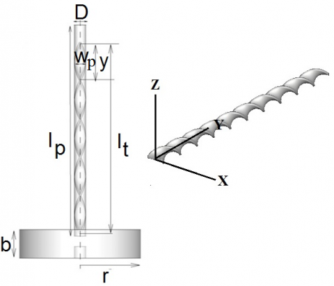
Figure 1 shows a sample of the geometries which used in this study. Where D, is the diameter of nozzle, lp, length of pipe, b, distance between nozzle exit and flat plate, lt, length and wt, width of twisted tape and y=lp/n where n is the number of twists. For generating swirls, twisted tape inside the pipe nozzle was used, which made from Aluminum of 2.5 mm in thickness, 16.5 mm in width (wt), and 300 mm (lt) in length. The dimension and placement of obstacles on the plate are shown in figure 2. Obstacles on the plate are cylindrical with the diameter and height of D. The mesh is unstructured. Detail of the computational domain and mesh generated in the case without obstacles is shown in figure 3.
Figure 1. Geometry used in this study
Figure 2. Dimension and placement of obstacles on impingement plate in 3 modes
Figure 3. Computational domain and mesh generated for the case without obstacles
The boundary conditions for this problem with the heated impingement plate is made of aluminum with constant flux (1kW) can be given as: no-slip conditions of the velocity at impingement plate, pressure outlet for side wall with gauge pressure equals zero and velocity inlet for the nozzle. The cylindrical obstacles have equal wall flux, which is the same with the impingement plate. The fluid in the nozzle is air with temperature of 275 K and Pr = 0.7. To investigate the impact of mesh size on calculations and results, the height of the first computational cell near the impingement plate is changed. In this test, b/D=2, Re=23,000 and growth rate are 1.07. Table 1 shows grid number for different mesh size.
Table 1. Grid number for differnt mesh
|
Y= 0.001D |
Y= 0.002D |
Y= 0.003D |
Y= 0.01D |
Y= 0.05D |
|
|
357315 |
336975 |
321720 |
260700 |
169170 |
Grid number |
Figure 4 shows the local Nusselt number distribution graph along X axis on the impingement plate. It shows that the maximum difference between the two grid with y= 0.002 D and y= 0.001 D is equal to 2.42 %.
Figure 4. Local Nusselt number distribution along X axis on impingement plate
Figure 5. Local Nusselt number distribution along X axis on impingement plate in b/D=2
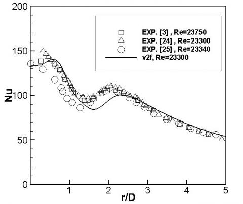
For validation, the distribution of local Nusselt number along X axis on the impingement plate in b/D=2 was examined. The simulation result was compared with the experimental data [3, 24, and 25]. Figure 5 shows distribution of local Nusselt number along X axis on the impingement plate that has a reasonable accuracy.
It is observed that v2-f turbulence model accurately predicts the data. This model has maximum of 12.85 % error with the results of Ref. [25] in the region that second peak occurs (2< r/D <2.2). v2-f model predicts the second peak on the curve but it cannot predict properly its size and location.
4.1 Without obstacle
In this paper, simulation is done for b/D=2, 4 and 0 ≤ r/D ≤ 5. Heat transfer in jet impingement with swirling flow, is examined. The swirls were generated using twisted tapes. Twist numbers in this research include 0 (straight tape), 5, 8, 10 and 12 twists. The Reynolds number is 20,000. Figure 6 shows Y plus on the impingement plate on Z axis in b/D = 2
Figure 6. Y plus on the impingement plate on Z axis in b/D=2
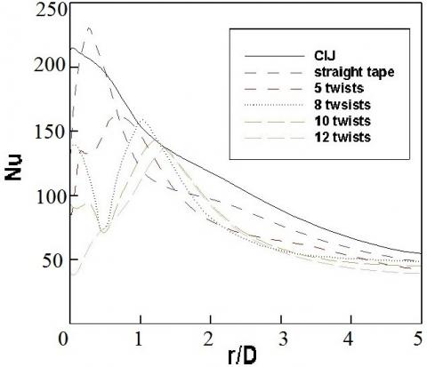
Figure 7 shows the Local Nusselt number distribution along Z axis on the impingement plate without obstacle, in (a), b/D=2 and (b), b/D=4. It is observed that in b/D=2, by increasing twist number, second peak of curve, disappears. It can be due to loss of axial momentum of impinging jet. While by increasing the b/D to 4, twisted tape causes to appear the secondary peak in the Nusselt number curve. It is due to the vortex formation near the stagnation point.
(a) b/D=2
(b) b/D=4
Figure 7. Local Nusselt number distribution along Z axis on impingement plate without obstacle
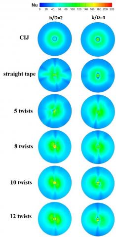
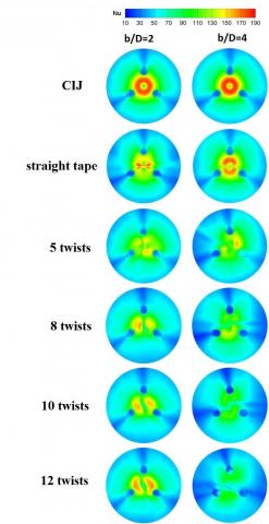
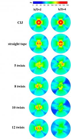
Figure 8 shows the contour of the Nusselt number. For CIJ, the maximum rate of heat transfer occurs in the center of the nozzle (near the stagnation point). Also for straight tape and 5 twisted tape, the maximum rate of heat transfer occurs near the stagnation region. With inserting the twisted tape in the pipe nozzle, the heat-transfer area is divided into two parts, which with increasing twist ratio, this separation area will be bigger.
Figure 8. Contour of the Nusselt number on impingement plate without obstacle
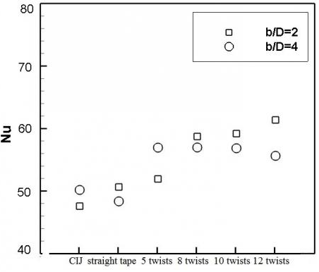
Figure 9 shows the average Nusselt number of impingement plate. It is seen that in b/D=4, when the twist ratio increases, the average Nusselt number decreases, which could be due to loss of the local momentum flux of the jets. In b/D=2, with using the twisted tape with 12 twists, the average Nusselt number is maximum, although the increase in the average Nusselt number is negligible compared to CIJ (0.2 percent).
Figure 9. Average Nusselt number of impingement plate without obstacle
4.2 With obstacle
In this section, the effect of obstacles on heat transfer of the impingement plate is analyzed. For this purpose, three modes were simulated:
1- Impingement plate with one obstacle, 2-Three obstacles with triangular arrangement, 3-Four obstacles with square arrangement, are examined.
4.2.1 Impingement plate with one obstacle
As mentioned earlier, to create an obstacle, a cylinder with a diameter and height of D is used. Figure 10 shows contour of local Nusselt number for b/D=2, 4.
Figure 10. Contour of local Nusselt number on impingement plate with one obstacle for b/D=2, 4
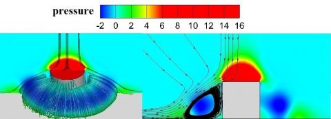
Figure 11 shows the vector flow, around the cylinder. A region that has been shown by the arrows on the figure has a negative pressure. Fluid jet, after hitting the obstacle redirected to the impingement plate. Then with changing the direction and re-acceleration, hits cylinder wall and creates vortices around the cylinder.
Figure 11. Vector flow around the cylinder
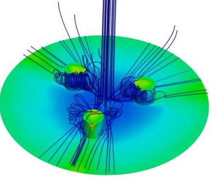
Flow around the cylinder and vortex created in the low-pressure region are shown in Figure 12 (Re=20000). According to figures 10 and 12, the results indicate that in the area which has been developed the vortex, less heat transfer occurs and the temperature is higher than the surrounding area.
Figure 12. Vortex created around obstacle
Figure 13 shows the average Nusselt number on the impingement plate. In b/D=4, the average Nusselt number of the impingement plate in 8 twists, is maximum (14 percent more than CIJ) and in straight tape, is minimum.
In b/D=2, with decreasing of twists number, the average Nusselt number steadily increased. In 12 twists, the average Nusselt number is 29 percent more than CIJ.
Figure 13. Average Nusselt number on impingement plate with one obstacle
Figure 14 shows stream lines around the cylinder in b/D=4 and in two cases; a) 8 twists and b) CIJ. In case of b, fluid flow collisions to obstacle and then collisions to the impingement plate. But in the case of a, without hitting the obstacle, it straightly collisions to the impingement plate, which could be the reason for the higher heat transfer of case b than case a.
Figure 14. Stream lines around the obstacle in b/D=4 and in two cases; a) 8 twists and b) CIJ
4.2.2 Impingement plate with triangular arrangement of obstacles
In this section, triangular arrangement of three cylindrical obstacles has been used on the impingement plate. The distance between the center of the impingement plate and center of the cylinder, is 2D and the angles between centers of cylinders are 120° Figure 15 shows the contour of the Nusselt number.
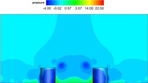
Figure 16(a) shows the contour of the pressure on the plane perpendicular to the impingement plate and figure 16(b) shows fluid stream lines around the obstacle in CIJ. It is seen that around the cylindrical obstacles, vortex is created due to low pressure area. In this case, wall of the obstacle that is adjacent to the stagnation region is cooler than the area behind the obstacle.
Figure 15. Contour of the Nusselt number on impingement plate with three obstacles
(a)
(b)
Figure 16. (a): Contour of the pressure on the plane perpendicular to the impingement plate in CIJ. (b): Fluid stream lines around the obstacle in CIJ
Figure 17 shows the average Nusselt number of impingement plate. In b/D=2, the average Nusselt number of impingement plate is maximum in CIJ and it is minimum in 8 twists. In b/D=4, with increasing of twists number, the average Nusselt number steadily decreases and swirling flow causes heat transfer loss.
Figure 17. Average Nusselt number of impingement plate with three obstacles
4.2.3 Impingement plate with square arrangement of obstacles
In this section, square arrangement of four cylindrical obstacles has been used in impingement plate. The distance between the center of the impingement plate and the center of the cylinder, is 2D. Figure 18 shows the contour of the Nusselt number.
Figure 18. Contour of the Nusselt number on impingement plate with four obstacles
Figure 19 shows a graph of average Nusselt number on the impingement plate. In b/D=4, with increasing of twists number, the average Nusselt number steadily decreases and swirling flow doesn’t enhance heat transfer. Also, in b/D=2, the average Nusselt number in CIJ, is maximum and in 8 twists is minimum.
Figure 19. Average Nusselt number on impingement plate with four obstacles
In this paper, simultaneous influence of swirling flow and obstacle on the plate is investigated. To investigate the effect of swirling flow to heat transfer, five twisted tapes with different twist ratios have been used in the nozzle. In order to investigate the effect of obstacles on the impingement plate on heat transfer, three different modes of arrangements of obstacles; impingement plate with an obstacle, three obstacles with triangular arrangement, four obstacles with square arrangement, is used. The results show that:
(1) In b/D=2, the highest rate of heat transfer occurs in 12 twists and the minimum rate of heat transfer occurs in 5 twists. In b/D=4, swirling flow doesn’t enhance heat transfer. In 12 twists, heat transfer is minimum and in CIJ, is maximum.
(2) When the impingement plate has one obstacle, in b/D=2, using twisted tape with 12 twists, the Nusselt average would be 29 percent higher than the CIJ. With increasing of twists number, the average Nusselt number steadily increased. In b/D=4 swirling flow improves heat transfer. In 8 twists, heat transfer is maximum and it is 14 percent more than CIJ. In case which triangular arrangement of three cylindrical obstacles is used, swirling flow doesn’t improve heat transfer. In CIJ heat transfer is maximum. The minimum heat transfer in b/D=2 is in 8 twists and in b/D=4 is in 12 twists. The results in square arrangement of obstacles are the same with triangular arrangement of obstacles.
|
l |
Length, m |
|
b |
distance between nozzle and flat plate, m |
|
D w y r |
diameter of nozzle, m width, m length of one twis, m radial coordinate |
|
U V K h ${q}''$ |
normal velocity, m.s-1 radial velocity, m.s-1 turbulent kinetic energy, j.kg-1 convective heat transfer coefficient (${q}''$/(Tw-Tj)), w.m-2.k-1 heat flux,W.m-2 |
|
P Νu Re Pr |
pressure, N.m-2 Nusselt number (hD/k) Reynolds number (VjD/ν) Prandtl number |
|
Greek symbols |
|
|
ν |
Kinematic viscosity, m2.s-1 |
|
Subscripts |
|
|
p |
pipe |
|
t |
twisted tape |
|
w j |
wall jet |
[1] Jambunathan K., Lai E., Moss M.A., Button B.L. (1992). A review of heat transfer data for single circular jet impingement, International Journal of Heat and Fluid Flow, Vol. 13, pp. 106-115. DOI: 10.1016/0142-727X (92)90017-4
[2] Lytle D., Webb W. (1994). Air jet impingement heat transfer at low nozzle-plate spacings, International Journal of Heat and Mass Transfer, Vol. 37, pp. 1687-1697. DOI: 10.1016/0017-9310(94)90059-0
[3] Baughn J.W., Shimizu S. (1989). Heat transfer measurements from a surface with uniform heat flux and an impinging jet, Journal of Heat Transfer, Vol. 111, pp. 1096-1098. DOI: 10.1115/1.3250776
[4] Ledezma G., Morega A.M., Bejan A. (1996). Optimal spacing between pin fins with impinging flow, Journal of Heat Transfer, Vol. 118, pp. 570-577. DOI: 10.1115/1.2822670
[5] Behnia M., Parneix S., Durbin P. (1997). Accurate modeling of impinging jet heat transfer, Center for Turbulence Research, Annual Research Briefs, pp. 149-164.
[6] Huang L., El-Genk M.S. (1998). Heat transfer and flow visualization experiments of swirling, multi-channel, and conventional impinging jets, International Journal of Heat and Mass Transfer, Vol. 41, pp. 583-600. DOI: 10.1016/S0017-9310(97)00123-3
[7] Brignoni L.A., Garimella S.V. (1999). Experimental optimization of confined air jet impingement on a pin fin heat sink, IEEE Transactions on Components and Packaging Technologies, Vol. 22, pp. 399-404. DOI: 10.1109/6144.796542
[8] Maveety J.G., Hendricks J.F. (1999). A heat sink performance study considering material, geometry, nozzle placement, and reynolds number with air impingement, Journal of Electronic Packaging, Vol. 121, pp. 156-161. DOI: 10.1115/1.2792678
[9] Hee L.D., Youl W.S., Taek K.Y., Suk C.Y. (2002). Turbulent heat transfer from a flat surface to a swirling round impinging jet, International Journal of Heat and Mass Transfer, Vol. 45, pp. 223-227. DOI: 10.1016/S0017-9310(01)00135-1
[10] Zuckerman N., Lior N. (2005). Impingement heat transfer: correlations and numerical modeling, Journal of Heat Transfer, Vol. 127, pp. 544-552. DOI: 10.1115/1.1861921
[11] Bakirci K., Bilen K. (2007). Visualization of heat transfer for impinging swirl flow, Experimental Thermal and Fluid Science, Vol. 32, pp. 182-191. DOI: 10.1016/j.expthermflusci.2007.03.004
[12] Yang H.Q., Kim T., Lu T.J., Ichimiya K. (2010). Flow structure, wall pressure and heat transfer characteristics of impinging annular jet with/without steady swirling, International Journal of Heat and Mass Transfer, Vol. 53, pp. 4092-4100. DOI: 10.1016/j.ijheatmasstransfer.2010.05.029
[13] Nanan K., Wongcharee K., Nuntadusit C., Eiamsa-ard S. (2012). Forced convective heat transfer by swirling impinging jets issuing from nozzles equipped with twisted tapes, International Communications in Heat and Mass Transfer, Vol. 39, pp. 844-852. DOI: 10.1016/j.icheatmasstransfer.2012.05.002
[14] Nuntadusit C., Wae-hayee M., Bunyajitradulya A., Eiamsa-ard S. (2012). Visualization of flow and heat transfer characteristics for swirling impinging jet, International Communications in Heat and Mass Transfer, Vol. 39, pp. 640-648. DOI: 10.1016/j.icheatmasstransfer.2012.03.002
[15] Salman S.D., Kadhum A.A.H., Takriff M.S., Mohamad A.B. (2014). Experimental and numerical investigations of heat transfer characteristics for impinging swirl flow, Advances in Mechanical, Vol. 6, pp. 1-9. DOI: 10.1155/2014/631081
[16] Sivakumar K., Rajan K. (2015). Experimental analysis of heat transfer enhancement in a circular tube with different twist ratio of twisted tape inserts, International Journal of Heat and Technology, Vol. 33, No. 3, pp. 158-162. DOI: 10.18280/ijht.330324
[17] Kaliakatsos D., Cucumo M., Ferraro V., Mele M., Galloro A., Accorinti F. (2016). CFD analysis of a pipe equipped with twisted tape, International Journal of Heat and Technology, Vol. 34, No. 2, pp. 172-180. DOI: 10.18280/ijht.340203
[18] Carlomagno M.G., Ianiro A. (2014). Thermo-fluid-dynamics of submerged jets impinging at short nozzle-to-plate distance: a review, Experimental Thermal and Fluid Science, Vol. 58, pp. 15-35. DOI: 10.1016/j.expthermflusci.2014.06.010
[19] Aminia Y., Mokhtarib M., Haghshenasfarda M., Barzegar G.M. (2015). Heat transfer of swirling impinging jets ejected from Nozzles with twisted tapes utilizing CFD technique, Case Studies in Thermal Engineering, Vol. 6, pp. 104-115. DOI: 10.1016/j.csite.2015.08.001
[20] Greco C.S., Castrillo G., Crispo C.M., Astarita T., Cardone G. (2015). Investigation of impinging single and twin circular synthetic jets flow field, Experimental Thermal and Fluid Science, Vol. 74, pp. 354-367. DOI: 10.1016/j.expthermflusci.2015.12.019
[21] Tesar V., Trávnícek Z., Peszynski K. (2016). Impinging jets controlled by fluidic input signal, Sensors and Actuators A: Physical, Vol. 249, pp. 85-92. DOI: 10.1016/j.sna.2016.08.013
[22] Ahmed Z., Al-Abdeli Y., Guzzomi F. (2017). Flow field and thermal behaviour in swirling and non-swirling turbulent impinging jets, International Journal of Thermal Sciences, Vol. 114, pp. 241-256. DOI: 10.1016/j.ijthermalsci.2016.12.013
[23] ANSYS FLUENT® Academic Research, release 14.5, Help System, Coupled Field Analysis Guide, ANSYS, Inc.
[24] Baughn J.W., Hechanova A.E., Yan X. (1991). An experimental study of entrainment effects on the heat transfer from a flat surface to a heated circular impinging jet, Journal of Heat Transfer, Vol. 113, pp. 1023-1025. DOI: 10.1115/1.2911197
[25] Yan X. (1993). A preheated-wall transient method using liquid crystals for the measurement of heat transfer on external surfaces and in ducts, Ph.D. dissertation, Department of Mechnaical Engineering, University of California, California, USA.