OPEN ACCESS
In this paper a solar heating and cooling (SHC) system composed of a flat-plate solar collector array, a hot water storage tank, a single-effect LiBr–H2O absorption chiller, a cold water tank, a cooling tower and an auxiliary gas-fired boiler was considered. The solar heating system was designed and modelled to satisfy the requirements for space heating, domestic hot water as well as space cooling. The system operates to serve an Italian multi-family house located in Naples (south of Italy). This study was performed by using the dynamic simulation software TRNSYS considering the transient nature of the building and occupant driven loads. The performance of the solar heating and cooling system was analyzed upon varying: (i) solar collectors area, (ii) size of both the hot water tank and (iii) cold water tank.
Finally, the performance of the optimized SHC system was compared, from energy, environmental and economic points of view, with those associated to a conventional system composed of a natural gas-fired boiler and an air-cooled water electric chiller fed by the national electric grid in order to evaluate the potential benefits of the proposed system in comparison to a conventional system.
Solar heating and cooling, Absorption systems, Carbon dioxide emissions, Energy saving, Operating costs.
Nowadays, energy saving and low environmental impact have stimulated the search for not only more efficient methods of energy production but also to increase the use of renewable energy sources [1-2]. Meanwhile, the growing demand for space cooling, space heating, and domestic hot water in residential buildings continues to increase primary energy consumption. These three thermal demands can be satisfied with different types of equipment and system configurations. One method for sustainable development is to adopt solar heating and cooling (SHC) systems mainly consisting of solar collectors coupled with thermally-activated absorption chillers.
Several scientific papers investigated the operation of solar powered absorption heating and cooling systems highlighting that SHC systems allow to save primary energy (up to more than 60%) as well as reduce the operating costs (up to 40%) in comparison to traditional electric vapor compression heat pump systems [3].
In the following some of these studies are briefly described. Xu et al. [4] considered a SHC system based on solar collectors array, an absorption chiller, a main storage tank, and a heating storage tank serving an medium-sized office building in Atlanta, Georgia, that was optimized with respect to life-cycle energy, economic, and environment performance. The results showed that a system composed of 800 m2 of solar collector area, with a slope angle of about 27°, a main tank volume less than 15 m3 and a heating tank volume equal to 12 m3 was the optimal solution. Calise et al. [5] analyzed the potential of maximizing primary energy savings with a combination of different configurations of SHC systems for an office building located in south Italy by means of TRNSYS software [6]. The performances of the SHC were compared to a traditional electric heat pump system and the best results showed a primary energy saving of about 37%. In addition, Calise [7] investigated the energetic and economic feasibility of a solar-assisted heating and cooling system (SHC) for different types of school buildings and Italian climates. The SHC system investigated in [7] was based on coupling of evacuated solar collectors with a single-stage LiBr–H2O absorption chiller; auxiliary energy for both heating and cooling was supplied by an electric-driven reversible heat pump (EHP) serving school buildings located in three different Italian climatic zones. The results showed a significant primary energy saving (64.7%) with respect to a traditional Heating, Ventilating and Air Conditioning system, a winter solar fraction equal to 46.2% and a summer solar fractions of about 27.7%. However, these studies analyzed SHC systems serving school or office buildings, very few studies were performed with reference to the case of residential applications. Arsalis and Alexandrou [8] investigated a SHC system serving a single-family house located in Nicosia (Cyprus), consisting of a flat-plate solar collector array, a hot water storage tank and an absorption chiller unit. The hot water storage tank was also connected to an auxiliary heater (diesel-fired boiler) to supplement solar heating, when needed. In [8] a parametric study was also conducted and finally the system was compared to an EHP system through a cost analysis. The results showed that the optimum combination of solar collector area and volumetric capacity of the hot water storage tank were 70 m2 and 2.0 m3, respectively; from an economic point of view, the study showed that the SHC system was unfavorable for adoption in comparison to the EHP systems capital cost. Deng et al. [9] developed and optimized a solar system consisting of solar collectors and a CO2 heat pump for a residential test building in Shanghai. It was investigated whether the heat pump was a feasible option for auxiliary heating. The results showed that the average COP value of the heat pump was 2.38, while the solar fraction was 0.69 for the whole heating period.
The literature review highlighted that only simplified building models were assumed. Moreover, these analyses were mainly focused on the energy and economic points of view, whereas the environmental impact was often scarcely investigated.
In this paper a SHC system composed of a flat-plate solar collector array, a hot water storage tank, a single-effect LiBr-H2O absorption chiller, a cold water tank, a cooling tower and an auxiliary gas-fired boiler was considered. The SHC system was designed and modelled to satisfy the requirements for space heating, domestic hot water as well as space cooling. The system operates to serve an Italian multi-family house (MFH) located in Naples (latitude: 40°5146"80 North; longitude: 14°1636"12 East). This study was performed by using the dynamic simulation software TRNSYS [6] considering the transient nature of building and occupant driven loads. This software was widely used in current literature to evaluate and predict the performance of different energy systems upon varying the operating scenarios [10-20].
The performance of the solar heating and cooling system were analyzed upon varying: (i) solar collectors area (30 and 60 m2 were considered), (ii) size of both the hot water tank (1.0, 1.5 and 2.5 m3 were considered) and (iii) cold water tank (3.0, 4.0 and 4.5 m3 were considered). Nine configurations of the SHC system were simulated.
Finally, the performance of the optimized SHC system was compared with that associated to a conventional system composed of a natural gas-fired boiler and an air-cooled water chiller fed by the national electric grid. The comparison was performed in terms of primary energy consumption, carbon dioxide equivalent emissions and operating costs according to the Italian scenario; the updated Italian tariffs associated to both fuel consumption and electric energy purchased from the grid were taken into account.
The proposed system, shown in Figure 1, includes a flat-plate solar collector array (SC), a hot water storage tank (HWT), a single-effect LiBr–H2O absorption chiller (ABHP), a cold water tank (CWT), a cooling tower (CT) and an auxiliary gas-fired boiler (B), five pumps (P1, P2, P3, P4 and P5), five flow diverters (D1, D2, D3, D4 and D5) and five flow mixers (M1, M2, M3, M4 and M5). The system under investigation is devoted to satisfying the space heating load, the domestic hot water requirements and the space cooling load of MFH, composed of three floors and located in Naples (south Italy, latitude: 40°5146"80 North; longitude: 14°1636"12 East). Fan-coils are used as hydronic terminals inside the building. The hot water storage tank is equipped with two internal heat exchanger (IHE1 and IHE2) and it is used for both heating purposes and domestic hot water production. The thermal energy recovered from the solar collector array is transferred to the HWT by using the first internal heat exchanger (IHE1). IHE2 is devoted to produce domestic hot water (DHW) during the whole year; in case of the water temperature leaving IHE2 (Tout,IHE2) is lower than 45°C, the required additional heat is provided by the auxiliary natural gas-fired boiler. This auxiliary natural gas-fired boiler is connected in series to the HWT to provide additional heat in order to guarantee the set-point temperature at the outlet of the HWT (Tout,HWT). During the heating period, hot water from the HWT is used to satisfy the space heating demand; during the summer, hot water from the HWT is used to activate the ABHP to generate chilled water to cover the space cooling demand. The cooling energy is transferred from the ABHP to the CWT by means of the internal heat exchanger IHE3.
The Italian Law [21] limits the operating time of heating systems during winter depending on the region where the plant is located; thus the simulations were performed from November 15th to March 31st with one-minute simulation time step. The Italian law does not limit the operating time of cooling systems during summer; as a consequence, the duration of the cooling period is selected from April 1st to November 14th. Two set-point temperatures (Troom) are imposed for both heating (Troom = 20.0°C from 6:00 to 9:00 and from 16:00 to 22:00, while Troom = 18.0°C during the rest of the day) as well as cooling period (Troom = 26.0°C from 9:00 to 16:00 and Troom = 24.0 °C during the rest of the day). A controller dead band equal to 1°C is used.
Both tanks are modelled with 10 isothermal temperature layers to better represent the stratification in the tank, where the top layer is 1 and the bottom layer is 10.
Table 1 reports the control logic for the boiler, the ABHP and pumps. The operation of the pump P1 depends on:
The operation of ABHP, P2, P3 and P4 during the cooling season depends of the temperature at node 9 within the CWT (T9,CWT).
Table 1. On-off control logic of the SHC system.
|
|
Monitored parameters |
ON |
OFF |
|
Operation of P1 |
TSC,out, T1,HWT, T10,HWT |
(TSC,out – T10,HWT) ≥ 10 °C & T1,HWT ≤ 95 °C |
(TSC,out –T10,HWT) ≤ 3 °C or T1,HWT > 95 °C |
|
Operation of ABHP, P2, P3 and P4 during cooling season |
T9,CWT |
T9,CWT ≥ 15 °C |
T9,CWT < 9 °C |
|
Operation of Boiler for DHW production |
Tout,IHE2, $\dot{\mathrm{V}}_{\mathrm{DHW}}$ |
$\dot{\mathrm{V}}_{\mathrm{DHW}}$≠0 & Tout,IHE2 ≤ 41 °C |
Tout,IHE2 ≥ 45 °C or $\dot{\mathrm{V}}_{\mathrm{DHW}}$=0 |
|
Operation of Boiler for cooling purposes |
Tout,HWT |
Tout,HWT ≤81 °C |
Tout,HWT ≥ 85 °C |
|
Operation of Boiler for heating purposes |
Tout,HWT |
Tout,HWT ≤ 51 °C |
Tout,HWT ≥ 55 °C |
Figure 1. Schematic of the proposed SHC system
In particular, the ABHP device is turned off if T9,CWT falls below 9 °C and is then turned on when T9,CWT becomes equal to its set-point (15 °C). The on-off operation of the boiler depends on the temperature Tout,IHE2 and DHW flow rate ( $\dot{\mathrm{V}}_{\mathrm{DHW}}$), for domestic hot water production, and on the temperature Tout,HWT for both heating as well as cooling purposes.
The multi-family house is basically a multiplication of a single family house type building geometry. The single flat is representative of a typical Italian residential application. All the flats have the same useable surface (96.0 m2); the net height of each floor is 3.0 m; five windows (double glazing), for a total area equal to 10.8 m2, are considered for each floor. Both the heating load as well as the cooling load are determined using the multi-zone building model in TRNSYS (Type 56a).
A specific EnergyPlus weather data file [22] is used for evaluating the climatic conditions of the city. In this study, the thermal transmittance values of the walls and windows are equated to the given threshold values required by the Italian Law [23]. A different stochastic occupancy profile is assumed for each flat according to [24] with a maximum number of 4 occupants for each flat is considered. For each single flat, a daily electric demand profile resulting from the operation of both the lighting systems and other domestic appliances, is assumed according to the reference values suggested in [24]. A different stochastic electrical load profile is assumed for each flat. Each electrical demand profile is coherent with the occupancy profiles and the daily electric energy consumptions considered in this study is about 103.6 Wh/m2 for the whole building. The base DHW profile is issued by [25,26] with an average basic load of 400 l/day per flat in the time scale of 1 minute. A different stochastic DHW profile is assumed for each flat. Each DHW profile is modified by considering the occupancy profiles (no people → no DHW requirements); consequently, the average basic load is decreased to around 260 l/day. The internal gains profile suggested by the Italian Standard UNI/TS 11300-1 [27] is used in this work; the suggested profile is modified by considering the assumed occupancy profiles.
The ABHP is the model WFC-SC5 commercialized by the company Yazaki [28]. In particular, the nominal cooling capacity of the ABHP system is equal to 17.6 kW. The single-effect LiBr–H2O absorption chiller operates at an inlet generator temperature of 70-95°C and the electrical consumption is equal to 48 W [28]. The ABHP is modeled in TRNSYS by the Type 107 calibrated based on manufacturer data.
System performances are investigated upon varying the HWT volume (VHWT), CWT volume (VCWT) and SC area (ASC) by means of TRNSYS 17 [6]. Table 2 shows the configurations of the SHC system considered for the parametric study. The SC angle is assumed equal to 30° in order to harvest maximum irradiation over a year [29].
Table 2. Configurations of the SHC system for the parametric study
|
Case |
ASC (m2) |
SC Angle (°) |
VCWT (m3) |
VHWT (m3) |
|
A.01 |
30 |
30 |
3.0 |
1.0 |
|
A.02 |
30 |
30 |
3.0 |
2.5 |
|
A.03 |
30 |
30 |
4.5 |
1.0 |
|
A.04 |
30 |
30 |
4.5 |
2.5 |
|
A.05 |
60 |
30 |
3.0 |
1.0 |
|
A.06 |
60 |
30 |
3.0 |
2.5 |
|
A.07 |
60 |
30 |
4.5 |
1.0 |
|
A.08 |
60 |
30 |
4.5 |
2.5 |
The simulation data are used to compare the performance of the Base Case (VHWT=1.5 m3; VCWT=4.0 m3; ASC=30 m2) with those of the eight cases described in Table 2 from energy, environmental and economic points of view.
The percentage difference of primary energy consumptions (Ep) is used as an indicator for the energy comparison:
$\Delta E_{p}=\frac{E_{p, B a s c o s e}-E_{p, c o s s A i}}{E_{p, B a s c a s e}}$(1)
where Ep,BaseCase and Ep,CaseA.i are the primary energy consumption associated to the Base Case and the Case A.i (the case i-th for the parametric study), respectively.
A positive value of DEp indicates that the i-th case allows to reduce primary energy consumption in comparison to the Base Case.
The economic comparison between the Base Case and other cases is performed in terms of operating costs (OC). The operating costs due to both natural gas and electric energy consumptions are evaluated in detail according to the Italian scenario [30]. The following formula is used:
$\Delta O C=\frac{O C_{B a s c c a s e}-O C_{C a s e A i}}{O C_{B a s c a s e}}$(2)
A positive value of DOC indicates that the i-th case allows for a reduction in terms of operating costs in comparison to the Base Case.
The environmental comparison between the Base Case and other cases is carried out in terms of carbon dioxide equivalent emissions (CO2), considering a CO2 emission factor for electricity production equal to 0.573 kg/kWel [31] and a CO2 emission factor associated to the natural gas consumption equal to 0.207 kg/kWp [31]. The formula used to calculate this parameter is the following:
$\Delta C{{O}_{2}}=\frac{C{{O}_{2,BaseCase}}-\text{ }C{{O}_{2,CaseA.i}}}{C{{O}_{2,BaseCase}}}$ (3)
A positive value of DCO2 indicates that the i-th case allows a reduction in terms of CO2 emission in comparison to the Base Case.
In addition, the solar fraction indicator (Fsol) is taken into account during the parametric study: it is defined ad the ratio between the thermal energy recovered from the solar source (Eth,SC) and the total thermal energy required by the SHC system (Eth,total) during the whole year. In this work the Fsol is calculated as follows:
$F_{s o l}=\frac{E_{t h, S C}}{E_{t h, t o t a l}}=\frac{E_{t h, S C}}{E_{t h, A B H P}+E_{t h, H e a t i n g}+E_{t h, D H W}}$(4)
where Eth,ABHP is thermal energy required by the ABHP device, Eth,Heating is the thermal energy required for heating purposes and Eth,DHW is thermal energy required for DHW production. Finally, the best case resulting from the parametric study is compared with the conventional system by assuming for the conventional system (composed of the same boiler of the proposed system and an electric air-cooled chiller with a COP equal to 3.0) the same energy output of the proposed SHC system.
The proposed SHC system is simulated over the whole year by means of the software TRNSYS [6] in order to analyze the system performances upon varying the boundary conditions and to define the best case.
Figure 2 presents the thermal, cooling and electric energy flows associated to the Base Case for the proposed SHC system during the whole year. This figure highlights that:
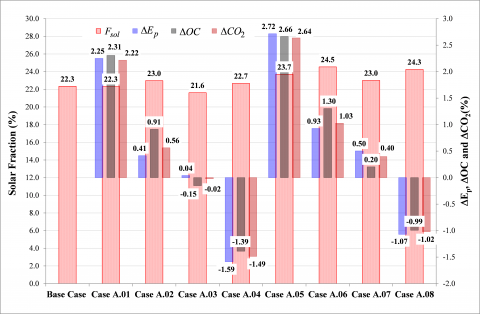
Figure 3 reports the annual values of Fsol on the left axis as a function of the configurations of the SHC system, while the values of DEp, DOC and DCO2 are indicated on the right axis. The Figure 3 shows that:
In addition, this figure highlights that increasing VHWT allows to increase the value of Fsol, while increasing VCWT reduces the value of solar fraction.
Considering the capital cost of the flat-plate solar collectors (around 350 €/m2), the authors suggest Case A.01 as the best compromise between energy, environmental and economic results.
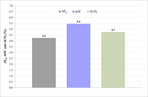
Figure 4 shows the annual values of DEp, DOC and DCO2 resulting from the comparison between the conventional system and the Case A.01. This figure highlights that the annual values of the three above-mentioned parameters are positive; this means that the proposed SHC system allows to reduce the annual primary energy consumption (equal to 4.2%), the operation costs (equal to 5.4%) and the carbon dioxide equivalent emissions (equal to 4.7%) in comparison to a conventional system.
In this paper, the yearly operation of a SHC system composed of a flat-plate solar collector array, a hot water storage tank, a single-effect LiBr–H2O absorption chiller, a cold water tank, a cooling tower and an auxiliary gas-fired boiler was investigated by means of transient simulations. Nine configurations of the SHC system were simulated in order to define the best case from energy, environmental and economic points of view. The simulation results demonstrated that the best case is the Case A.01, characterized by ASC=30 m2, VHWT=1.0 m3, VCWT=3.0 m3 with a value of Fsol equal to 22.3%. The analysis highlighted that the best configuration of the SHC system is more convenient with respect to the conventional system assumed as reference from energy, economic and environmental points of view (DEp=4.2%, DOC=5.4% and DCO2=4.7%).
Figure 2. Thermal, electric and cooling energy flows associate to Base Case for the proposed SHC system during the whole year
Figure 3. Annual values of Fsol as a function of the configurations of the SHC system, and DEp, DOC, DCO2 values resulting from the comparison between Base Case and other cases
Figure 4. Annual values DEp, DOC and DCO2 resulting from the comparison between the conventional system and the Case A.01
[1] Nasrin, R. and Alim, M., A., “Thermal performance of nanofluid filled solar flat plate collector”, Int. J. Heat Technol., vol. 33, no. 2, pp 17-24, 2015. DOI: 10.18280/ijht.330203.
[2] Mazzeo, D., Matera, N., Bevilacqua, P., Arcuri, N., “Energy and economic analysis of solar photovoltaic plants located at the university of Calabria”, Int. J. Heat Technol., vol. 33, no. 4, pp 41-50, 2015. DOI: 10.18280/ijht.330406.
[3] Siddiqui, M.U. and Said, S.A.M., “A review of solar powered absorption systems,” Renew Sustain Energy Rev, vol. 42, pp. 93–115, 2015. DOI: 10.1016/j.rser.2014.10.014.
[4] Xu, D., Qu, M., Hang, Y. and Zha, F., “Multi-objective optimal design of a solar absorption cooling and heating system under life-cycle uncertainties,” Sustain Energy Technol Assess, vol. 11, pp. 92–105, 2015. DOI: 10.1016/j.seta.2015.07.001.
[5] Calise, F., Palombo, A. and Vanoli, L., “Maximization of primary energy savings of solar heating and cooling systems by transient simulations and computer design of experiments,” Appl Energy, vol. 87, pp. 524–540, 2010. DOI: 10.1016/j.apenergy.2009.08.033.
[6] Solar Energy Laboratory, TRNSYS., “A transient system simulation program,” Tech. rep., University of Wisconsin. Madison, USA 2004.
[7] Calise, F., “Thermoeconomic analysis and optimization of high efficiency solar heating and cooling systems for different Italian school buildings and climates,” Energy Build, vol. 42, pp. 992–1003, 2010. DOI: 10.1016/j.enbuild.2010.01.011.
[8] Arsalis, A. and Alexandrou, A.N., “Parametric study and cost analysis of a solar-heating-and-cooling system for detached single-family households in hot climates,” Sol Energy, vol. 117, pp. 59–73, 2015. DOI: 10.1016/j.solener.2015.04.024.
[9] Deng, S., Dai, Y.J. and Wang, R.Z., “Performance optimization and analysis of solar combi-system with carbon dioxide heat pump,” Sol Energy, vol. 98, pp. 212–225, 2013. DOI: 10.1016/j.solener.2013.10.001.
[10] Ciampi, G., Rosato, A., Scorpio, M. and Sibilio, S., “Experimental analysis of a micro-trigeneration system composed of a micro-cogenerator coupled with an electric chiller,” Appl Therm Eng, vol. 73, pp. 1307-1320, 2014. DOI: 10.1016/j.applthermaleng.2014.09.018.
[11] Ciampi, G., Rosato, A., Scorpio, M. and Sibilio, S., “Energy, environmental and economic dynamic simulation of a micro-cogeneration system serving an Italian multi-family house,” Energy Procedia, vol. 78, pp. 1141-1146, 2015. DOI: 10.1016/j.egypro.2015.11.076.
[12] Ciampi, G., Rosato, A. and Sibilio, S., “Yearly operation of a building-integrated microcogeneration system in south Italy: energy and economic analyses,” Int J Low Carbon Technol, vol. 9, pp. 331-346, 2014. DOI: 10.1016/j.egypro.2015.11.076.
[13] Ciampi, G., Rosato, A., Scorpio, M. and Sibilio, S., “Energy performance of a residential building-integrated micro-cogeneration system upon varying thermal load and control logic,” Int J Low Carbon Technol, vol. 11, pp. 75-88, 2016. DOI: 10.1093/ijlct/ctt075.
[14] Rosato, A., Sibilio, S. and Ciampi, G., “Dynamic performance assessment of a building-integrated cogeneration system for an Italian residential application,” Energy Build, vol. 64, pp. 343-358, 2013. DOI: 10.1016/j.enbuild.2013.05.035.
[15] Rosato, A., Sibilio, S. and Scorpio, M., “Dynamic performance assessment of a residential building-integrated cogeneration system under different boundary conditions. Part I: Energy analysis,” Energy Convers Manage, vol. 79, pp. 731-748, 2014. DOI: 10.1016/j.enconman.2013.10.001.
[16] Rosato, A., Sibilio, S. and Scorpio, M., “Dynamic performance assessment of a residential building-integrated cogeneration system under different boundary conditions. Part II: environmental and economic analyses,” Energy Convers Manage, vol. 79, pp. 749-770, 2014. DOI: 10.1016/j.enconman.2013.09.058.
[17] Ciampi, G., Rosato, A., Scorpio, M. and Sibilio, S., “Energy and economic evaluation of retrofit actions on an existing historical building in the south of Italy by using a dynamic simulation,” Energy Procedia, vol. 78, pp. 741-746, 2015. DOI: 10.1016/j.egypro.2015.11.085.
[18] Ciampi, G., Rosato, A., Scorpio, M., Sibilio, S. and Akisawa, A., “Building-integrated trigeneration system: Energy, environmental and economic dynamic performance assessment for Italian residential applications,” Renewable Sustainable Energy Rev, In Press, Corrected Proof, Renewable and Sustainable Energy Reviews, 2016. DOI: 10.1016/j.rser.2016.02.011i.
[19] Yaïci, W. and Entchev, E., “Performance prediction of a solar thermal energy system using artificial neural networks,” Appl Therm Eng, vol. 73, no. 1, pp. 1348-1359, 2014. DOI: 10.1016/j.applthermaleng.2014.07.040.
[20] Yaïci, W. and Entchev, E., “Adaptive Neuro-Fuzzy Inference System modelling for performance prediction of solar thermal energy system,” Renewable Energy, vol. 86, pp. 302-315, 2016. DOI: 10.1016/j.renene.2015.08.028.
[21] Decree of President of Italian Republic n.412/93 <http://efficienzaenergetica.acs.enea.it/doc/dpr412-93.pdf>
[22] EnergyPlus. <http://apps1.eere.energy.gov/buildings/energyplus/cfm/weather_data3.cfm/region=6_europe_wmo_region_6/country=ITA/cname=Italy>
[23] Italian Decree n. 311/06. <http://www.artechint.com/attestato-energetico.pdf>
[24] Richardson, I., Thomson, M., Domestic electricity demand model - simulation example. Loughborough Universitys Institutional Repository (2010), <http://hdl.handle.net/2134/5786>
[25] <http://sel.me.wisc.edu/trnsys/trnlib/library15.htm#IEA26Load>
[26] <http://sel.me.wisc.edu/trnsys/trnlib/iea-shc-task26/iea-shc-task26-load-profiles-description-jordan.pdf>
[27] UNI/TS 11300-1. Energy performance of buildings Part 1: Evaluation of energy need for space heating and cooling.
[28] Yazaki. <http://www.yazaki-airconditioning.com/products/wfc_water_fired_chiller.html>
[29] Joint Research Center. <http://re.jrc.ec.europa.eu/pvgis/solres/solreseurope.htm#Fig1>
[30] Italian Regulatory Authority for Electricity and Gas. <www.autorita.energia.it>
[31] Angrisani, G., Roselli, C. and Sasso, M.,. “Experimental assessment of the energy performance of a hybrid desiccant cooling system and comparison with other air-conditioning technologies,” Appl Energy, vol. 138, pp. 533–545, 2015. DOI: 10.1016/j.apenergy.2014.10.065.