OPEN ACCESS
The resin infusion is a manufacturing technology usually applied to produce structures made of composite materials widely employed in automotive, marine and aerospace industries. This process consists on the injection of a polymeric resin in a closed mold composed of porous medium and non-porous channels, which facilitates the resin propagation along the mold domain. The main purpose here is to show that Constructal Design can be applied to guide the design of this kind of process. More precisely, it is investigated the influence of geometry of a two dimensional resin flow in I and T-shaped non-porous channels intruded into a rectangular plate composed of a porous medium over resin time injection along all domain, mimicking an infusion process. The I-shaped channel has one Degree of Freedom (DOF) while T-shaped channel has three DOFs. The other degree of freedom for both problems is the ratio between the height and length of the porous plate. For all simulations the ratio between the channel and plate volume is constant (f = 0.05). The conservation equations of mass and momentum for the resin-air mixture and one equation for transport of volumetric fraction of resin are solved with the Finite Volume Method (FVM). The interaction between the phases is treated with the method Volume of Fluid (VOF) and resistance of porous medium is taken into account with Darcy’s law. Results showed that Constructal Design improves nearly 140 % and 139 % in resin time injection for I and T-shaped channels without formation of voids inside the plate domain. The best shape achieved with I-shaped channel is that one with higher penetration into the porous plate, as expected. However, for T-shaped channel an intermediate configuration led to the best results, contrarily to what was noticed for previous studies of cavities where the best shapes are obtained when the simple and bifurcated branches have the highest penetration inside the high resistance domain.
Constructal Design, Liquid Resin Infusion, Numerical Simulation, I-shaped Channel, T-shaped Channel.
The employment of composite materials in several applications in automotive, marine and aerospace fields has grown significantly due to several advantages of these materials. For instance, it can be mentioned the high strength, low density, excellent corrosion resistance and low cost of maintainance of composites. In this sense, several industrial techniques have been developed for the manufacturing of composite materials. Among them, liquid composite molding processes (LCM) such as resin transfer molding (RTM), light resin transfer molding (LRTM) and liquid resin infusion (LRI) processes have been widely applied to produce several components [1, 2, 3, 4].
Liquid resin infusion (LRI) processes are promising manufacturing routes to produce large, thick, and complex structural parts and consists on the injection of a polymeric resin in a closed mold composed of porous medium and non-porous channels, which make easier the resin propagation along the mold domain [5]. One of the main shortcomings of this kind of process is the difficult to control the mold filling step, mainly the resin front on small dimensions and complex geometries. As a consequence, several studies has been performed into the analytical, experimental and numerical framework in order to improve the comprehension about the resin flow in the infusion process [6].
Into the numerical realm, Poodts et al. [1] developed and validated a finite element code (more precisely the PAM-RTM) of a ship runway through the definition of a standardized experiment for the characterization of the laminates to obtain reliable permeability data. Isoldi et al. [4] performed a numerical study of the resin flow in RTM applications with a numerical code which does not have a specific RTM module. In this study, several cases were numerically solved and compared with analytical, experimental and numerical results. Moreover, a new computational methodology was developed to simulate a Light Resin Transfer Molding (LRTM) process, which consists of the injection of the resin into a mold through an empty injection channel (without porous medium) where the resin flows around the perimeter of the mold. In spite of several numerical and experimental studies, none has been seen about the evaluation of the influence of geometry over the resin flow in the infusion process. The sole exception found by the authors is the work of [7] where Constructal Design was employed to evaluate the effect of the non-fibrous geometry over the injection time of an Light Resin Transfer Molding (LRTM) manufacturing process.
It is worth to mention that in the industrial field, trial and error approach is usually employed for the definition of non-porous channels locations, which can led to high time of injections and failure during early stages of production of a new component. In this sense, Constructal Design is recommended for rationalization of design in this kind of manufacturing process. Constructal Design is the method used to evaluate geometries in every flux systems based on objectives and constraints. The physical principle used to explain the generation and evolution of design (configuration, shape, structure, pattern, rhythm) unifying animate and inanimate flux systems is the Constructal Law [8]. Constructal Law states that if a system has freedom to morph, it develops in time the flow architecture that provides easier access to the currents that flow through it [8, 9, 10]. Constructal Law has been employed to explain deterministically the generation of shape and structure in nature, for instance, in the formation of global circulation and climate [11], design of human and animals movement [12]. Moreover, it can be used as an powerful tool for evaluation of patterns evolution in urban design, traffic, transportation, social dynamics [13], economy and in many engineering problems, such as: design of electronics, fuel cells, turbines, wave energy, mechanic of materials, refrigeration, fundamental problems of heat transfer (specially cavities intruded into conductive walls and fins) and rationalization of renewable energy sources [14, 15, 16, 17, 18, 19, 20]. Therefore, Constructal Law can be considered as the unifying principle of design for every flow system.
The present work aims to employ Constructal Design to guide the design of a resin infusion process. More precisely, it is investigated the influence of geometry of a two dimensional resin flow in I and T-shaped non-porous channels intruded into a rectangular plate composed of a porous medium over resin time injection along all domain. This resin flow simulation mimicks the infusion process. The I-shaped channel has the ratio H0/L0 (ratio between the thickness and length of the non-porous channel) as Degree of Freedom (DOF), while the T-shaped channel has three DOFs: H0/L0 (ratio between the thickness and length of the tributary channel), H1/L1 (ratio between the length and thickness of bifurcated channels) and L0/L1 (ratio between the thicknesses of tributary and bifurcated channels). For all simulations the ratio between the channel and plate volume is constant (f = 0.05). The conservation equations of mass and momentum for the resin-air mixture and one equation for transport of volumetric fraction of resin are solved with the Finite Volume Method (FVM) [21, 22]. The interaction between the phases is treated with the method Volume of Fluid (VOF) and the resistance of the porous medium is taken into account with Darcy’s Law. More precisely, the simulations are performed using the Computational Fluid Dynamics code FLUENT [23].
In the resin infusion process, resin flows through a fibrous reinforcement which can be modelled as a porous medium. Therefore, this flow can be assumed to follow the Darcy’s Law, which states that the flow rate of resin per unit area is proportional to the pressure gradient and inversely proportional to the resin viscosity [24]. The mathematical equation for this phenomenon is given by:
$V_{i}=-\frac{K_{i j}}{\mu} \nabla P$(1)
where Vi is the velocity vector, m is the viscosity of the resin, Kij is the permeability tensor of the fiber reinforcement, Ñ is the gradient operator, P is the pressure and the indexes i, j = 1, 2, 3 represent the x, y and z directions, respectively.
Considering resin with constant physical properties and as an incompressible fluid, the mass conservation equation can be stated as:
$\nabla \cdot V_{i}=0$(2)
In the VOF method, the momentum, continuity and volume fraction transport equations must be solved simultaneously. In this work, the VOF solution is obtained with the FLUENT® software – a general CFD (Computational Fluid Dynamic) package based on the Finite Volume Method (FVM) which includes a VOF module for the solution of problems with two or more immiscible fluids where the position of the interface between the fluids is of interest [23]. A single set of momentum equations is applied to all fluids, and the volume fraction of each fluid in every computational cell is tracked throughout the domain [4].
For the LRI simulation, the two phases involved in the problem are the resin (liquid phase) and the air (gaseous phase). Thus, the model is composed of the continuity equation, given by:
$\frac{\partial \rho}{\partial t}+\nabla \cdot\left(\rho V_{i}\right)=0$(3)
the equation for the resin volume fraction f , defined by:
$\frac{\partial f}{\partial t}+\nabla \cdot\left(f V_{i}\right)=0$(4)
and the momentum equation, given by:
$\frac{\partial\left(\rho V_{i}\right)}{\partial t}+\nabla \cdot\left(\rho V_{i} V_{i}\right)=-\nabla p+\nabla \cdot\left[\mu \tau_{i j}\right]+\rho g_{i}+F_{i}$(5)
being r the density, t the time, τij the stress tensor, gi the gravitational acceleration vector and Fi an external force vector. In the present model, porous media are modeled by adding a source term to the standard momentum equations such as:
$F_{i}=-\frac{\mu}{K_{i j}} V_{i}$(6)
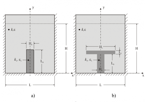
The analysed problem consists of a transient, laminar, two-dimensional resin flow in a porous medium, as illustrated in Figs. 1(a) and 1(b) for I and T-shaped channels, respectively. In order to simulate the liquid resin infusion process, channels without porous medium are inserted along the domain with porous medium to facilitate the resin impregnation along all the mold. In Figs. 1(a) and 1(b) these channels are represented in the dark gray region, while the porous region is represented with light gray. In both cases, the flow is caused by the imposition of a pressure difference between the inlet of resin (lower region of non-porous channel) and the outlet region (upper surface of the porous medium). It is considered an inlet pressure of Pin = 1.0 ´ 105 Pa and at the outlet it is imposed a pressure of Pout = 0 Pa. For the other surfaces (with dashed lines) the non-slip and impermeability boundary condition is imposed (v1 = v2 = 0 m/s). Concerning the thermophysical properties of the resin it is considered a density of r = 916 kg/m³ and a dynamical viscosity of m = 0.06 Pa.s. For the porous medium it is considered a permeability of k = 3.0´10-10 m² and porosity of e = 0.88. For non-porous medium it is considered a permeability of k1 = 9.99´109 m² and a porosity of e1 = 0.0. The problem with I-shaped channel is subjected to two constraints, the porous rectangular area:
A=HL(7)
and the non-porous channel area:
$A_{0}=H_{0} L_{0}$(8)
For the T-shaped channel problem, the rectangular porous area is also maintained constant and it is given by Eq. (7). The other constraint is the non-porous T-shaped channel area, which is given by:
$A_{T}=H_{0} L_{0}+H_{1} L_{1}$(9)
The problem for the I-shaped channel has two degrees of freedom: H/L and H0/L0, while the problem for the T-shaped channel has three degrees of freedom: H0/L0, H1/L1 and L0/L1. For all simulations it is considered H/L = 1.0 with H = L = 0.5 m. It is worthy to mention that a few additional height is taken into account to avoid the influence of the upper surface over the measurements performed in the dashed line inside the domain shown in Figs. 1(a) and 1(b). The main purpose of this problem is to obtain the geometry by means of Constructal Design which minimizes the time injection of resin in the mold.
Figure 1. Computational domain of the liquid resin infusion process for: a) I-shaped channel, b) T-shaped channel
For the numerical simulation of the conservation equations of mass and momentum, a commercial code based on the Finite Volume Method (FVM) is employed [23]. The solver is pressure-based and all simulations were performed by upwind and PRESTO for spatial discretizations of momentum and pressure, respectively. The velocity-pressure coupling is performed by the PISO method, while the GEO-RECONSTRUCTION method is employed to tackle with the volumetric fraction. Moreover, under-relaxation factors of 0.3 and 0.7 are imposed for the conservation equations of continuity and momentum, respectively. More details concerned with the numerical methodology can be obtained in the works [21, 22].
The numerical simulations were performed using a computer with two dual-core Intel processors with 2.67 GHz clock and 8 GB ram memory. It is used Message Passing Interface (MPI) for parallelization. For the temporal discretization it is employed a time-step of Δt = 1.0×10⁻³ s. Concerning the spatial discretization, the domain was shared in several rectangular finite volumes and a grid independence test was performed to define the refinement employed for all simulations. Table 1 shows the number of volumes, the time injection for mold filling and the processing time required to perform the simulations for each evaluated grid for an I-shaped non-porous channel with H/L = 1.0 and H0/L0 = 0.25. When the difference between the results obtained with two successive grids was lower than 1.0 %, it is considered that the employed mesh is independent. In this sense, it is employed a grid with 18,271 rectangular finite volumes.
Table 1. Grid independence test for I-shaped non-porous channel with H/L = 1.0 and H0/L0 = 0.25
|
Number of Volumes |
Time Injection (s) |
Difference (%) |
Processing Time (s) |
|
1,209 |
188.3 |
----- |
43,026 |
|
4,636 |
185.1 |
1.69 |
78,387 |
|
18,271 |
182.9 |
1.18 |
126,456 |
|
72,451 |
181.3 |
0.87 |
184,882 |
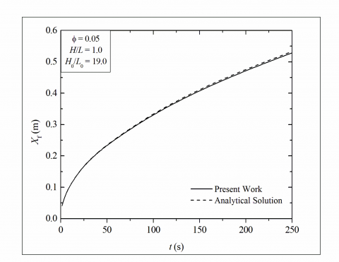
In order to evaluate the numerical methodology employed here, the time for filling of porous medium with resin obtained here for a simplified case and that achieved analytically for a rectilinear flow predicted in previous works of literature [4, 7, 25] are compared. The simplified case consists on a resin flow in an I-shaped non-porous channel with high magnitude for the ratio H0/L0, in such way that H0 = L. The purpose is to simulate with the present numerical model a rectilinear case. An analytic solution for the placement of resin front line as function of time is given by [25]:
$X_{f}=\sqrt{\frac{2 K P_{0} t}{\mu \varepsilon}}$(10)
where K is the permeability in rectilinear direction, P0 is the injection pressure, t is the time of resin advancement, m is the dynamic viscosity and e is the porosity in the porous medium.
For achievement of numerical results, a monitoring line is created in the center of domain, more precisely it is a line that overlaps the y-axis. The line was defined by the following points: P1 (x1 = 0.3 m, y1 = 0.0256 m) and P2 (x2 = 0.3 m, y2 = 0.75 m). The coordinate x1 = x2 represents the center of domain in x-direction, while y1 represents the placement of interface between non-porous channel and porous medium and y2 represents the exit of channel. Figure 2 shows the placement of resin front line as function of time predicted numerically with the method used here and that one predicted analytically in the literature. As can be seen, results showed an excellent agreement, verifying the method used in the present work.
For the achievement of a well succeeded molding it is necessary to eliminate completely the residual air inside the porous medium. The formation of micro voids due to partial impregnation of resin inside the fibrous reinforcement can led to failure of final product. In this sense, together with the time injection of resin inside the domain it is also required that permanent voids do not occurs inside the plate domain.
To obtain the injection time, it is created a monitoring line defined by the following points: P1 (x1 = 0.0 m, y1 = 0.5 m) and P2 (x2 = 0.6 m, y2 = 0.5 m). When the resin flow crosses completely the monitoring line, i.e., when the volume fraction along the whole line is f = 1.0, it is considered that the infusion process is finished. It is also considered a few space of 0.05 m in both sides of the fibrous mold with the purpose to prevent the formation of voids in the region of the plate which will be used in future applications.
Figure 2. Comparison between the placement of resin flow as function of time obtained in the present work and analytical solution
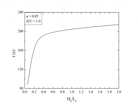
To evaluate the influence of the I-shaped channel intruded into the porous rectangular plate over the time injection of resin in the mold, several simulations with different ratios of H0/L0 are performed. In all cases, the channel fraction area was kept constant (f = 0.05). Figure 3 shows the effect of ratio H0/L0 over the resin molding time injection along all domain. It can be noticed that the decrease of H0/L0 leads to a decrease of resin injection time (t), i.e., when the channel has the highest penetration inside the porous domain towards the outlet region. The once optimized ratio of H0/L0 is obtained for (H0/L0)o = 0.0625 and leads to an once minimized resin time injection of tm = 88.8 s. On the opposite, the highest ratio of H0/L0 (H0/L0 = 2.0) leads to the worst performance with a resin infusion time of t = 214.3 s, which represents a fluid dynamic performance 140 % inferior than that achieved for the best shape.
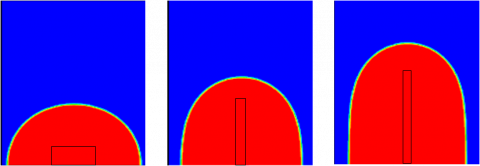
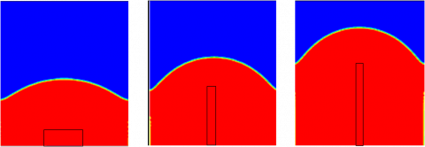
In order to illustrate the influence of the I-shaped channel over the behavior of resin flow inside the domain the resin volume fraction along the domain is presented for two different time steps in Fig. 4 (t = 40.0 s) and Fig. 5 (t = 80.0 s). In the figures, the red region represents the resin, while the blue region represents the air. Regions with other colors (yellow and green) represents regions with voids, i.e, 0.0 < f < 1.0. Figs. 4(a) and 5(a) illustrate the resin flow for the ratio H0/L0 = 2.0, while Figs. 4(b) and 5(b) depict the flow for H0/L0 = 0.125 and Figs. 4(c) and 5(c) shows the resin flow for H0/L0 = 0.0625. It can be observed that for the highest ratios of H0/L0 the resin tends to flow from the lower to the higher region of porous domain. In the beginning of the process for the case with H0/L0 = 2.0, the resin flows in radial direction forming a geometry similar to an ellipse with higher semi-axis in x-direction than in y-direction. As the process goes on, the resin front line flows toward superior region of porous medium. Moreover, the front line is more advanced in central region than near lateral surfaces of the porous rectangular plate due to non-slip condition in the lateral surfaces and by the need to filling lower corners of the porous medium with resin. As the ratio of H0/L0 decreases to H0/L0 = 0.125 and 0.0625 the resin intrudes into the porous medium in a placement nearer to the outlet section of domain than for the cases with the highest ratios of H0/L0. Other interesting observation is that in the lateral regions of the porous medium, the resin flows almost rectilinear from the lateral surface of non-porous medium toward the lateral surfaces of the porous rectangular domain. The physical mechanism for this difference is concerned with the most uniform distribution of the resin flow inside the domain for elongated channels, i.e., according to Constructal Principle of Optimal Distribution of Imperfections.
Figure 3. Effect of the ratio H0/L0 over the injection time of resin into the porous mold with I-shaped non-porous channel for f = 0.05 and H/L = 1.0.
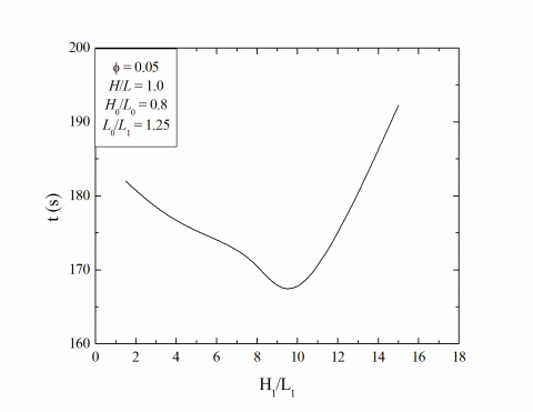
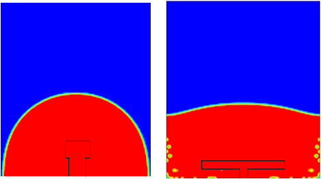
For the T-shaped channel, it is first evaluated the effect of the ratio H1/L1 over the resin time injection for constant ratios of H/L = 1.0, H0/L0 = 0.8 and L0/L1 = 1.25, as depicted in Fig. 6. The parameters imposed led to a formation of T-shaped channel flow restricted in the lower region of the cavity. In Fig. 6 can be noticed that there is one intermediate global optimal geometry. For this case, the optimal shape is obtained for (H1/L1)o = 10.0. This geometry leads to an once minimized time injection of tm = 165.5 s, which is nearly 12 % and 18 % lower than that obtained for the lowest and highest ratios of H1/L1 evaluated here. It is worthy to mention that, the lowest ratios of H1/L1 represent T-shaped channels that tend to I-shaped shapes. In the present problem, the increase of the bifurcated channel lengths leads to formation of micro voids spread along the plate. Most of voids are formed in the corner of T-channel when the resin flow changes from the single channel to the bifurcated channel and few vortex re generated. This vortex generation represents new irreversibilities of the system and demand the injection of more resin at the inlet to eliminate the generated voids. As a consequence, the resin injection time increases substantially for the highest magnitudes of H1/L1. In order to illustrate this behavior Fig. 7 shows the resin flow inside the mold at instant of time t = 50.0 s for two different T-shaped channels: H1/L1 = 1.5 (Fig. 7(a)) and (H1/L1)o = 10.0 (Fig. 7(b)). For the lowest ratio of H1/L1, the formation of voids is not observed, while for the optimal ratio the generation of few voids can be noticed. For the optimal case showed here, the injection of more resin in the inlet removes the few generated voids noticed in Fig. 7(b). However, there are cases where the generated voids are permanent and cannot be removed and the manufactured peace must not be used. In this sense, it is considered here an infinite resin time injection. One example can be seen in Fig. 8 for the case with H0/L0 = 0.05, L0/L1 = 10.0, H1/L1 = 8.0 for two different instants of time: t = 10.0 s (Fig. 8(a)) and t = 60.0 s (Fig. 8(b)).
Figure 4. Resin flow inside the mold at instant of time of t = 40.0 s for three different geometries of I-shaped channel: a) H0/L0 = 2.0, b) H0/L0 = 0.125, c) H0/L0 = 0.0625.
Figure 5. Resin flow inside the mold at instant of time of t = 80.0 s for three different geometries of I-shaped channel: a) H0/L0 = 2.0, b) H0/L0 = 0.125, c) H0/L0 = 0.0625.
Figure 6. Effect of the ratio H1/L1 over the time injection of resin for a T-shaped channel
Figure 7. Resin flow inside the mold at instant of time of t = 50.0 s for two different T-shaped channels: a) H1/L1 = 1.5, b) H1/L1 = 10.0
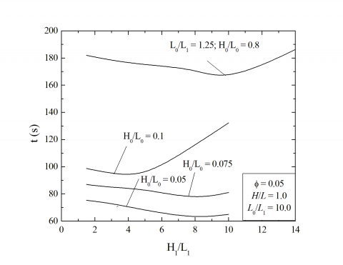
In a general sense, it is observed that the injection time is minimized when the single channel has a higher penetration into the porous medium. So, three new different ratios of H0/L0 are tested and the resin time injection is obtained, as illustrated in Fig. 9. It can be seen that when the single channel has a higher penetration into the porous medium, the resin time injection decreases. It is also observed that the effect of H1/L1 over (t) also changes for different values of H0/L0. The best shape obtained for (H1/L1)o = 8.0 leads to a tm = 76.0 s, which is nearly 17 % better than the best I-shaped channel and 139 % higher than the worst T-shaped channel. It can also be seen in Fig. 9 that for the ratio H0/L0 = 0.05, the time required for resin pass completely by the monitoring line is lower than the other evaluated cases (H0/L0 = 0.075 and 0.1). In spite of this fact, for every cases with H0/L0 = 0.05, permanent voids are generated, which make impossible the future use of the generated peace. In other words, the resin impregnation inside the whole domain is the most important parameter and must be taken into account for design in LRI process. It can also be noticed that the effect of the ratio H1/L1 over the time of infusion, as well as the optimal shapes, changed with different ratios of H0/L0 and L0/L1 evaluated, showing that these DOFs deserves future investigations.
Figure 8. Resin flow with formation of permanent voids: a) t = 10.0 s, b) t = 60.0 s
Figure 9. Effect of the ratio H1/L1 for different values of the ratio H0/L0
In the present work Constructal Design was applied to guide the design of a liquid resin infusion process. More precisely, it was investigated the influence of geometry of a two dimensional resin flow in I and T-shaped non-porous channels intruded into a rectangular plate composed of a porous medium over resin time injection along the domain. The I- and T-shaped channels have one and three DOFs, respectively. For all simulations the ratio between the channel and plate volume was constant (f = 0.05). The conservation equations of mass and momentum for the resin-air mixture and one equation for transport of volumetric fraction of resin were solved with the Finite Volume Method (FVM). The interaction between the phases was treated with the method Volume of Fluid (VOF) and resistance of porous medium is taken into account with Darcy’s law.
Results showed the importance of employment of Constructal Design for minimization of time resin injection into the porous medium. The best shapes found for I and T-shaped channels were nearly 140 % and 139 % better than the worst shape for each configuration. The best shape achieved with I-shaped channel was that one with the higher penetration into the porous plate, as expected. However, for T-shaped channels intermediate configurations led to the best results, contrarily to what was noticed for previous studies of cavities intruded into conducting solid walls. This difference is caused by the generation of irreversibilities mainly generated by the resin flow from the single channel to the bifurcated channel. Moreover, some geometries led to formation of permanent voids inside the domain which unfeasible the future employment of fabricated peace. Results also showed that the investigation of ratios H0/L0 and L0/L1 simultaneously can improve even more the performance of the T-shaped channel studied in this problem.
The authors L. A. O. Rocha, E. D. dos Santos, L. A. Isoldi, J. A. Souza and S. C. Amico thank CNPq and FAPERGS for finantial support. G. M. C. Magalhães thanks CAPES by Master Science scholarship.
1. Poodts, E., Minak, G., Dolcini, E., Donati, L., “FE analysis and production experience of a sandwich structure component manufactured by means of vacuum assisted resin infusion process,” Compos Part B Eng 53, 179-86, 2013. DOI: 10.1016/j.compositesb.2013.04.064.
2. Brouwer W., van Herpt E.C.F., Labordus M., “Vacuum injection moulding for large structural applications,” Compos Part Appl Sci Manuf 34(6), 551-558, 2003. DOI: 10.1016/S1359-835X(03)00060-5.
3. Yenilmez B., Sozer E.M., “Compaction of e-glass fabric preforms in the Vacuum Infusion Process, A: Characterization experiments,” Compos Part Appl Sci Manuf, 40(4), 499-510, 2009. DOI: 10.1016/j.compositesa.2009.01.016.
4. Isoldi L.A., Oliveira C.P., Rocha L.A.O., Souza J.A., Amico S.C., “Three-dimensional numerical modeling of RTM and LRTM processes,” J Braz Soc Mech Sci Eng 34(2),105-111, 2012. DOI: 10.1590/S1678-58782012000200001.
5. Wang P., Drapier S., Molimard J., Vautrin A., Minni J., “Numerical and experimental analyses of resin infusion manufacturing processes of composite materials,” J Compos Mater 46(13), 1617-1631, 2012. DOI: 10.1177/0021998311421990.
6. Goncharova G., Cosson B., Deléglise Lagardère M., “Analytical modeling of composite manufacturing by vacuum assisted infusion with minimal experimental characterization of random fabrics,” J Mater Process Technol 219, 173-180, 2015. DOI: 10.1016/j.jmatprotec.2014.12.010.
7. Isoldi L.A., Souza J.A., Dos Santos E.D., Marchesini R., Porto J., Letzow M., Rocha, L.A.O., Amico, S.C., “Constructal Design applied to the light resin transfer molding (LRTM) manufacturing process,” Proceedings of 22nd COBEM, Ribeirão Preto - SP, p. 8, 2013.
8. Bejan, A., Lorente S., The constructal law and the evolution of design in nature, Phys Life Rev 8(3), 209-240, 2011. DOI: 10.1016/j.plrev.2011.05.010.
9. Bejan, A., Shape and Structure, From Engineering to Nature, New York, Cambridge University Press, 324 p., 2000.
10. Bejan, A., Design with constructal theory, Hoboken, John Wiley & Sons, 529 p., 2008.
11. Bejan, A., Design in nature: how the constructal law governs evolution in biology, physics, technology, and social organization, New York, Doubleday, 296 p., 2012.
12. Reis, A.H., Bejan, A., “Constructal theory of global circulation and climate,” Int J Heat Mass Transf, 49(11-12), 1857-1875, 2006. DOI: 10.1016/j.ijheatmasstransfer.2005.10.037.
13. Bejan, A., Merkx, G.W., Constructal Theory of Social Dynamics, New York, Springer, 2007.
14. Rocha, L.A.O., Lorente, S., Bejan, A., editors. Constructal Law and the Unifying Principle of Design, New York, Springer New York, 2013. DOI: 10.1007/978-1-4614-5049-8.
15. Rocha, L.A.O., Lorenzini, E., Biserni, C., “Geometric optimization of shapes on the basis of Bejan’s Constructal theory,” Int Commun Heat Mass Transf, 32(10), 1281-1288, 2005. DOI: 10.1016/j.icheatmasstransfer.2005.07.010.
16. Xie, Z., Chen, L., Sun, F., “Geometry optimization of T-shaped cavities according to constructal theory,” Math Comput Model, 52(9-10), 1538-1546, 2010. DOI: 10.1016/j.mcm.2010.06.017.
17. Kundu, B., Bhanja, D., “Performance and optimization analysis of a constructal T-shaped fin subject to variable thermal conductivity and convective heat transfer coefficient,” Int J Heat Mass Transf, 53(1-3), 254-267, 2010. DOI: 10.1016/j.ijheatmasstransfer.2009.09.034.
18. Lorenzini, G., Biserni, C., Estrada, E.D., Isoldi, L.A., dos Santos, E.D., Rocha, L.A.O., “Constructal design of convective Y-Shaped cavities by means of genetic algorithm,” J Heat Transf, 136(7), 071702, 2014. DOI: 10.1115/1.4027195.
19. Kepes, R.M., Brum, R.S., Vaz, J., Rocha, L.A.O., dos Santos, E.D., Isoldi, L.A., “Numerical investigation about the improvement of the thermal potential of an Earth-Air Heat Exchanger (EAHE) employing the Constructal Design method,” Renew Energy 80, 538-551, 2015. DOI: 10.1016/j.renene.2015.02.041.
20. dos Santos, E.D., Machado, B.N., Lopes N., Souza, J.A., Teixeira, P.R.F., Gomes, M.N., Isoldi, L.A., Rocha, L. A. O., “Constructal Design of Wave Energy Converters,” In: Rocha LAO, Lorente S, Bejan A, editors. Constructal Law and the Unifying Principle of Design Internet]. New York, Springer New York, 2013. 275–94. DOI: 10.1007/978-1-4614-5049-8_16.
21. Versteeg, H.K., Malalasekera, W., An Introduction to Computational Fluid Dynamics: The Finite Volume Method, Pearson, 503 p., 2007.
22. Patankar, S.V., Numerical heat transfer and fluid flow, New York, McGraw Hill, 214 p., 1980.
23. FLUENT, Documentation Manual – FLUENT 6.3.16, Ansys Inc., 2007.
24. Morren, G., Bottiglieri, M., Bossuyt, S., Sol, H., Lecompte, D., Verleye, B., Lomov, S.V., “A reference specimen for permeability measurements of fibrous reinforcements for RTM,” Compos Part Appl Sci Manuf, 40(3), 244-250, 2009. DOI: 10.1016/j.compositesa.2008.11.011.
25. Jinlian, H., Yi, L., Xueming, S., “Study on void formation in multi-layer woven fabrics,” Composites A, 35, 595–603, 2004. DOI: 10.1016/j.compositesa.2003.11.007.