OPEN ACCESS
In this paper, lattice Boltzmann method is used to study the radiative effect on the temperature distribution inside the solid oxide fuel cell (SOFC). A two-dimensional model takes into account the ohmic losses in the different components of the SOFC is considered in this study. Schuster-Schwarzschild method is applied in order to model the radiative transfer in the electrolyte optically thin, whereas Rosseland method is applied for modelization the radiative transfer in the electrodes optically thick. Results show that the highest temperature is obtained in the electrolyte. Also, the radiative effect does not change the temperature distribution inside the SOFC; there is only a temperature reduction.
Conduction, Lattice Boltzmann method, Radiation, SOFC.
Due to their high electric efficiency, low emissions and fuel flexibility, solid oxide fuel cells (SOFC) are considered one of the most promising technologies for heat and power production. Calise et al. [1] studied numerically the effects of radiative heat transfer and electrochemical reactions in a tubular solid oxide fuel cell. The obtained results show that the radiative heat transfer dramatically contributes to the heat transfer between the SOFC and its air injection tube. Ho et al. [2] investigated numerically a planar anode supported solid oxide fuel cell with mixed conducting electrodes. The effects of the operating temperature, chemical species and current density distribution are studied. The found results show principally that for co-flow case, a sub-cooling effect manifests itself in the methane-rich region near the fuel entrance, while for counter-flow case a super-heating effect manifests itself somewhat further downstream, where all the methane is consumed. Damm et al. [3] studied radiative transport within the electrode and electrolyte layers of a solid oxide fuel cell, as well as surface-to surface radiation within the fuel and oxygen flow channels. The obtained results show that the radiative effect dramatically contributes to the temperature distribution inside the SOFC. Daun et al. [4] presented a detailed characterization of the thermophysical and radiative properties of the composite materials, which are then used to study numerically the temperature distribution inside the electrode and electrolyte layers of a planar SOFC. Contrary to the previously published literatures, the found results show that radiative heat transfer has a negligible effect on the temperature distribution. Murthy et al. [5] studied numerically the radiation heat transfer effects on mass and temperature distributions inside a solid oxide fuel cell. The obtained results show significant changes in the temperature distribution and parameters of the SOFC with the inclusion of radiation effects. VanderSteen et al. [6] studied numerically the heat transfer inside a solid oxide fuel cell. Material properties, chemical kinetics, and transport properties are considered to be functions of the temperature. A commercial computational code includes conduction, convection, and radiation in a participating media is used. The obtained results show that the radiation must be considered when modeling solid oxide fuel cells. Also, radiation effect is more important in tubular geometries. Xu et al. [7] used lattice Boltzmann method to study numerically the electrochemical performance of solid oxide fuel cell. The effects of different electrode geometrical and operating parameters on the cell performance were investigated. Results show that the developed electrochemical model based on LBM is useful for the optimization of SOFC. In the last few years, lattice Boltzmann method (LBM) has been widely used for modeling and solving many engineering applications. Mejri et al. [8] used lattice Boltzmann method to study 1-D conduction–radiation problem. The effects of the scattering albedo, conduction–radiation parameter and emissivity are investigated. The obtained results demonstrate that lattice Boltzmann method is an appropriate method for conduction–radiation problem. Mejri et al. [9] used lattice Boltzmann method to study MHD natural convection in a nanofluid filled enclosure. The obtained results show that the heat transfer is controlled by the thermal boundary conditions. Also, the heat transfer increases with the increase of Rayleigh number whereas the opposite behavior occurs with the increase of Hartmann number. Mahmoudi et al. [10] used lattice Boltzmann method to study the magnetic field inclination effects on nanofluid natural convection. The obtained results show that the Nusselt number and the nanoparticles behavior depend strongly upon the magnetic field direction. Mahmoudi et al. [11] used lattice Boltzmann method to study MHD natural convection cooling by two heat sinks vertically attached to the horizontal walls of a closed cavity filled with nanofluid. For low Rayleigh number, the obtained results show that the Nusselt number depends strongly on the heat sinks positions and the nanoparticles volume fraction.
The aim of this study is to investigate numerically the radiation effect on the temperature distribution inside the solid oxide fuel cell (SOFC). To model the radiative transfer inside the SOFC, the Rosseland method is applied for the electrodes optically thick whereas the Schuster-Schwarzschild method is used for the electrolyte optically thin. Lattice Boltzmann method (LBM) is applied to solve the energy equation. The LBM results are validated with previous numerical investigation and the effects of the electrolyte and electrodes thickness are researched.
2.1 Problem statement
The physical model considered here is represented in Fig.1. For all considered configurations, the operating temperature used in this study is Tf = 1173K. The cell width is fixed to H = 4mm while the width of the anode and cathode channels is fixed to H/2. The electrolyte and electrodes thickness of the different configurations studied are presented in Table 1.
Figure 1. Geometry of the present study with boundary conditions
The energy equation for the electrolyte and the electrodes is given by the following relation:
$\rho \mathrm{c}_{\mathrm{P}} \frac{\partial \mathrm{T}}{\partial t}=k \nabla^{2} \mathrm{T}-\vec{\nabla} \cdot \overrightarrow{\mathrm{q}}_{\mathrm{R}}+S_{\mathrm{Ohm}}$(1)
The SOFC components are considered semi transparent, they can absorb, scatter, and emit thermal radiation. ρ is the density, cp is the specific heat, k is the thermal conductivity, $\overrightarrow{\mathbf{q}}_{\mathrm{R}}$ is the radiative heat flux and SOhm is the ohmic heat source.
Table 1. Electrolyte and electrodes thickness fordifferent configurations
|
Thickness (μm) |
||
|
anode |
electrolyte |
cathode |
|
200 |
200 |
200 |
|
300 |
100 |
200 |
|
200 |
100 |
300 |
|
100 150 100 |
200 300 400 |
100 150 100 |
2.2 Ohmic source expression
For the different components of the SOFC (i: anode, cathode and electrolyte), the ohmic source is given by the following formula [12]:
$S_{\mathrm{Ohm} i}=\frac{j^{2}}{\sigma_{i}}$(2)
The current density "j" is considered constant inside the SOFC. The electrical conductivities for the different cell components are given by the following formulas:
$\sigma_{a n}=\frac{95 \times 10^{6}}{T} \exp \left(-\frac{1150}{T}\right)$
$\sigma_{c a}=\frac{42 \times 10^{6}}{T} \exp \left(-\frac{1200}{T}\right)$(3)
$\sigma_{e l}=3.34 \times 10^{4} \exp \left(-\frac{10300}{T}\right)$
2.3 Radiative properties
The experimental published data [13] show that SOFC electrodes are optically thick ($r_{L}=\beta L >>1$), Consequently, the Rosseland method can be used. The Rosseland radiative conductivity is is given by:
$k_{r}=\frac{16 n ? \sigma T^{3}}{3 \beta}$(4)
σ is the Stefan–Boltzmann constant (= 5.67x10⁻⁸ W m−2 K4), T is the local temperature (K), n is the refractive index (= 1.8) and β is the extinction coefficient, the extinction coefficients of the cathode and anode are respectively β = 106 and 104[13]. For Rosseland method, the radiative heat flux is given by:
$\vec{q}_{R}=-k_{r} \vec{\nabla} T$(5)
Contrary to the electrodes, the electrolyte is considered to be optically thin ($\tau_{L}=\beta L \leq 1$) [13] and isotropic non-diffusing gray medium [5]. Consequently, the Schuster–Schwarzschild two-flux method is applied to solve the radiative energy equation. For Schuster–Schwarzschild two-flux method, the radiative heat flux is given by:
$q_{R}=-\sigma\left(T_{t o p}^{4}-T^{4}\right) e^{-2 \kappa y} e^{2 \kappa L}+\sigma\left(T_{b o t t}^{4}-T^{4}\right) e^{-2 \kappa y}$(6)
L is medium thickness, Ttop and Tbottom are the thermal boundary conditions for a gray, non-scattering medium confined between two isothermal, parallel black walls.
2.4 Lattice Boltzmann simulation
Taking into account the different heat sources, , the discrete Boltzmann equation for D2Q9 lattice is given by [8]:
$\begin{aligned} f_{i}\left(\vec{x}+\vec{e}_{i} \Delta t, t+\Delta t\right) &=f_{i}(\vec{x}, t) \\-& \frac{1}{\tau}\left[f_{i}(\vec{x}, t)-f_{i}^{e q}(\vec{x}, t)\right]-\frac{\Delta t \mathbf{w}_{i}}{\rho \mathbf{c}_{\mathrm{P}}}\left(\vec{\nabla} \cdot \overrightarrow{\mathbf{q}}_{\mathrm{R}}-S_{\mathrm{Ohm}}\right) \end{aligned}$(7)
$f_{i}$ and $f_{i}^{e q}$ are respectively the distribution function and the equilibrium distribution function. $\vec{e}_{i}$ is the velocity along the direction i and $\tau$ is the relaxation time.
$\tau=\frac{3 \alpha}{\left|\vec{e}_{i}\right|^{2}}+\frac{\Delta t}{2}$(8)
Δt is the lattice time step and α is the thermal diffusivity. The weighting factors and the discrete velocity vectors are calculated as follows:
$e_{1,3}=( \pm 1,0) \frac{\Delta x}{\Delta t}, e_{2,4}=(0, \pm 1) \frac{\Delta x}{\Delta t}$
$e_{5,8}=( \pm 1, \pm 1) \frac{\Delta x}{\Delta t}, e_{0}=(0,0)$(9)
$\mathrm{w}_{0}=\frac{4}{9}, \mathrm{w}_{1,4}=\frac{1}{9}, \mathrm{w}_{5,8}=\frac{1}{36}$(10)
The temperature is obtained after summing $f_{i}$ over all direction:
$\mathrm{T}(\vec{x}, t)=\sum_{i=0,8} f_{i}(\vec{x}, t)$(11)
The equilibrium distribution function is calculated by the following formula:
$f_{i}^{e q}(\vec{x}, t)=\mathrm{W}_{i} \mathrm{T}(\vec{x}, t)$(12)
Lattice Boltzmann method was validated by the published results of Zitouni et al. [12] in order to check on the accuracy of the obtained results. The results are presented in Fig.2a-b. Its show for the configuration (an/el/ca: 100/200/100µm) the temperature distribution inside the SOFC, in the absence of the radiative effect. A good agreement between both compared results is found.
Figure 2. Temperature distribution without radiative effect (a) Zitouni et al. [12] (b) LBM
4.1. Without radiative effect
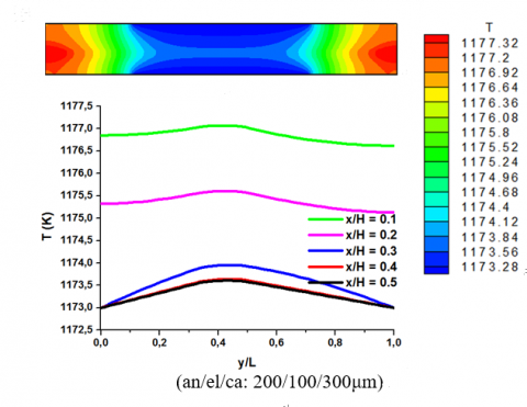
Fig.3 shows the temperature distributions inside the SOFC for two configurations: (an/el/ca: 200/100/300μm) and (300/100/200μm). For the both configurations, results show that the highest temperature is obtained in the electrolyte; this is due to the high heat loss in the low electric conductivity region. Also, Results show that the temperature distribution is non-uniform inside the SOFC, this is due in addition to the non-uniform ohmic loss, to the thermal boundary conditions imposed by the SOFC structure. The highest temperatures are located in the areas in contact with the interconnector (adiabatic areas); these boundaries act as resistance to heat diffusion, which increases the temperature in these regions. On the other hand, in the solid portion between the two channels (isotherm regions at the temperature Tf), the temperature increases weakly. This may be explained by the heat removal through the gas flowing in the anode and cathode channels. For the both considered configurations, results show that the maximum temperatures obtained is the same (1177.85K). The ohmic losses in the electrolyte are the ones primarily responsible for the maximum temperature inside the SOFC. Reversing cathode and anode thickness, while maintaining the electrolyte thickness preserved, does not affect the maximum temperature.
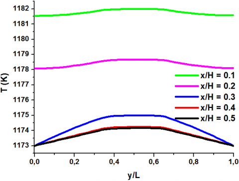
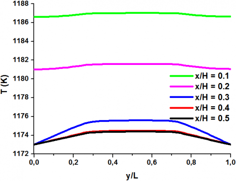
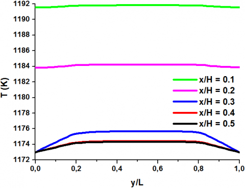
Fig.4 shows the temperature distributions inside the SOFC for three configurations: (an/el/ca: 200/200/200μm), (150/300/150μm) and (100/400/100μm). The maximum temperature is located in the electrolyte, in side of the interconnector. Increasing the electrolyte thickness while decreasing the electrodes thickness causes the increase of the temperature inside the SOFC. This is due to the low electrical conductivity of the electrolyte relative to that of the electrodes.
Figure 3. Temperature distribution without radiative effect
4.2. With radiative effect
Fig.5 shows the temperature distributions inside the SOFC for two configurations: (an/el/ca: 200/100/300μm) and (300/100/200μm). Results show that the radiative effect does not change the temperature distribution inside the SOFC; there is only a temperature reduction. Also, the maximum temperature is always reached in electrolyte layer. In addition, Fig.5 shows that contrary to the study without radiative effect, the maximum temperature for the configuration (an/el/ca: 300/100/200μm) is 1176.99K and 1177.32K for the configuration (200/100/300μm), a difference of 0.33K is found between both configurations. The origin of this difference can be attributed to the difference in optical properties between anode and cathode. the radiation effect and the electrodes thickness have a significant effect on the temperature distribution inside the SOFC for a conserved electrolyte thickness.
(an/el/ca: 200/200/200μm)
(an/el/ca: 150/300/150μm)
(an/el/ca: 100/400/100μm)
Figure 4. Temperature distribution without radiative effect
Figure 5. Temperature distribution with radiative effect
Table 2. shows the difference between the maximum temperatures inside the SOFC with and without the radiative effect (ΔTmax) for the both configurations: (an/el/ca: 200/100/300μm) and (300/100/200μm). Comparing the two configurations, the temperature difference is higher for the configuration with the highest anode thickness. This phenomenon is attributed to the high radiative conductivity of the anode. The Rosseland radiative conductivity of the anode is 100 times greater than that of the cathode (KR,an/KR,ca = βca/ βan = 100).
Table 2. Radiative effect on the maximum temperature
|
thickness (μm) (an/el/ca) |
Tmax (K) |
ΔTmax (K) |
|
|
without radiative effect |
with radiative effect |
||
|
(300/100/200) |
1177.85 |
1176.99 |
0.86 |
|
(200/100/300) |
1177.86 |
1177.32 |
0.54 |
Fig. 6 shows the temperature distributions inside the SOFC taking into account of the radiative effect for three configurations: (an/el/ca: 200/200/200μm), (150/300/150μm) and (100/400/100μm). Results show that the maximum temperature is always reached in the electrolyte layer. The highest temperature reduction by the radiative effect is obtained in the electrolyte. Also, the radiative effect increases with the electrolyte thickness augmentation. This behavior is attributed to the optical properties difference of the electrodes and the electrolyte: the electrolyte diffuses much more heat by radiation than the electrodes.
(an/el/ca: 200/200/200μm)
(an/el/ca: 150/300/150μm)
(an/el/ca: 100/400/100μm)
Figure 6. Temperature distribution with radiative effect
Table 3. shows the difference between the maximum temperatures inside the SOFC with and without the radiative effect (ΔTmax) for three configurations: (an/el/ca: 200/200/200μm), (150/300/150μm) and (100/400/100μm). Comparing the different configurations, results show that the temperature difference (ΔTmax) increases with the electrolyte thickness augmentation. The increase of the electrolyte thickness (optically thin) while reducing the electrodes thickness (optically thick) explained the temperature difference (ΔTmax) variation between the different configurations.
Table 3. Radiative effect on the maximum temperature
|
thickness (μm) An/el/ca |
Tmax (K) |
ΔTmax (K) |
|
|
without radiative effect |
with radiative effect |
||
|
200/200/200 |
1183.98 |
1182.95 |
1.03 |
|
150/300/150 |
1189.93 |
1188.56 |
1.37 |
|
100/400/100 |
1195.74 |
1193.94 |
1.80 |
In this paper, a two-dimensional study of the radiative effect on the temperature distribution inside SOFC is performed by the lattice Boltzmann method. The model takes into account the ohmic losses in the different components of the SOFC. Different configurations are considered in this study and some conclusions were summarized as follows:
While it may seem that the radiative effect is negligible within the SOFC due to the low thickness of the electrodes and electrolyte, this is not actually a reasonable assumption given the high operating temperature and the important ohmic losses in the electrolyte layer, which can promote the radiative effect.
[1] F. Calise, M. D. Accadia, G. Restuccia, “Simulation of a tubular solid oxide fuel cell through finite volume analysis: Effects of the radiative heat transfer and exergy analysis”, International Journal of Hydrogen Energy, vol. 32, pp. 4575-4590, 2007. DOI: 10.1016/j.ijhydene.2007.05.040.
[2] T.X. Ho, P. Kosinski, A.C. Hoffmann, A. Vik, “Numerical analysis of a planar anode-supported SOFC with composite electrodes”, International Journal of Hydrogen Energy, vol. 34, pp. 3488-3499, 2009. DOI: 10.1016/j.ijhydene.2009.02.016.
[3] D.L. Damm, A.G. Fedorov, “Radiation heat transfer in SOFC materials and components”, Journal of Power Sources, vol. 143, pp. 158-165, 2005. DOI: 10.1016/j.jpowsour.2004.11.063.
[4] K.J. Daun, S.B. Beale, F. Liu, G.J. Smallwood, “Radiation heat transfer in planar SOFC electrolytes”, Journal of Power Sources, vol. 157, pp. 302-310, 2006. DOI: 10.1016/j.jpowsour.2005.07.045.
[5] S. Murthy, A.G. Fedorov, “Radiation heat transfer analysis of the monolith type solid oxide fuel cell”, Journal of Power Sources, vol. 124, pp. 453-458, 2003. DOI: 10.1016/S0378-7753(03)00732-8.
[6] J.D.J. VanderSteen, J.G. Pharoah, “Modeling radiation heat transfer with participating media in solid oxide fuel cells” Fuel Cell Sci. Technol, vol. 3, pp. 62-67, 2005. DOI: 10.1115/1.2134738.
[7] H. Xu, Z. Dang, B.F. Bai, “Electrochemical performance study of solid oxide fuel cell using lattice Boltzmann method”, Energy, vol. 67, pp. 575-583, 2014. DOI: 10.1016/j.energy.2014.02.021.
[8] I. Mejri, A. Mahmoudi, M.A. Abbassi, A. Omri, “Lattice Boltzmann simulation of conduction-radiation heat transfer in a planar medium”, International Journal of Heat & Technology [Online], vol. 32, pp.213-218, 2014. Available: http://www.iieta.org/Journals/H%26TECH/ARCHIVE/Volume%2032%20No%201-2.
[9] I. Mejri, A. Mahmoudi, M.A. Abbassi, A. Omri, “Magnetic field effect on natural convection in a nanofluidfilled enclosure with non-uniform heating on both side walls”, International Journal of Heat & Technology [Online], vol. 32, pp.127-133, 2014. Available: http://www.iieta.org/Journals/H%26TECH/ARCHIVE/Volume%2032%20No%201-2.
[10] A. Mahmoudi, I. Mejri, M.A. Abbassi, A. Omri, “Lattice Boltzmann simulation of magnetic field direction effect on natural convection of nanofluid-filled cavity”, International Journal of Heat & Technology [Online], vol. 32, pp.9-14, 2014. Available: http://www.iieta.org/Journals/H%26TECH/ARCHIVE/Volume%2032%20No%201-2.
[11] A. Mahmoudi, I. Mejri, M.A. Abbassi, A. Omri, “Study of natural convection in a square cavity filled with nanofluid and subjected to a magnetic Field”, International Journal of Heat & Technology, vol. 34, pp.73-79, 2016. DOI: 10.18280/ijht.340111.
[12] B. Zitouni, H. Moussa, K. Oulmi, S. Saighi, K. Chetehouna, “Temperature field, H2 and H2O mass transfer in SOFC single: Electrode and electrolyte thickness effects”, international journal of hydrogen energy,vol.34, pp. 5032–5039, 2009. DOI: 10.1016/j.ijhydene.2008.12.085.
[13] D.L. Damm and A.G. Fedorov, “Spectral radiative heat transfer analysis of the planar SOFC”. J. Fuel Cell Sci. Technol, vol.2, no.4, pp.258–262, 2005. DOI: 10.1115/1.2041667.