OPEN ACCESS
Impact of diagonal swirler vane angle on combustion dynamic and NOx formation characteristic in a hybrid industrial combustor is numerically studied using a full compressible large eddy simulation approach. The predicted results show that increase the swirler vane angle enlarges the magnitude of the CTRZ and thus the coherent structure and off-axis motions of vortex cores which increase the pressure oscillations amplitude. Phenomenon of combustion instability does not occur due to the introduction of pilot diffusion flame. Formation rate of NOx is relatively slower in pilot diffusion flame, because excess air contained in pilot fuel streams dilutes the flame temperature. Regions with peak flame temperature and maximum formation rate of NOx located in vicinity to the sidewall of combustion chamber especially in the shell side. Proper increase of diagonal swirler vane angle to enlarges the divergence angle of flame and reduces the recirculation of hot gases and combustion products in outer recirculation zones to control peak temperature of flame is an effective means to control NOx emissions for this hybrid industrial combustor. Further increase the diagonal swirler vane angle will have relatively smaller impacts on compressing the NOx emission due to the confinement of combustion chamber.
Combustion chamber, Swirl angle, Combustion dynamic, NOx formation, Large eddy simulation.
Gas-steam combined cycle unit, as one of the most efficient heat-work conversion system has got rapid development in power generation since its creation [1]. Diffusion flame combustors are traditionally used in gas turbine combustion chamber due to their reliable performance and reasonable stability characteristics [1]. However, the emission of NOx is difficult to meet the requirements of increasingly strict regulations [2]. Some new combustion technologies have been introduced to gas turbine industry to ensure low NOx emission since mid-80s, which include lean premixed combustion, rich burn quick quench lean burn combustion and catalytic combustion. Among the above technologies, lean premixed combustion is the most promising technology for gas turbine industry in recent years [3]. In lean premixed combustion, fuel and air are premixed to avoid the formation of stoichiometric regions inside the combustion chamber [4]. Comparing to diffusion flame, premixed flames are by nature more susceptible to dynamic instabilities [5]. In consequence, swirlers and pilot fuel nozzle are needed to improve premixed combustion stabilization in most cases [5, 6].
In high swirl level flow, sufficiently degree of adverse pressure gradient is formed and a central toroidal recirculation zone (CTRZ) is generated in vicinity to the centerline of combustor [6]. Heat and active chemical species recirculate to the root of the flame which directly heat and ignite the incoming fuel/oxidant streams and thus improve flame stabilization [5]. Formation of the CTRZ is a form of vortex breakdown [5, 7-9]. Sarpkaya et al. [10, 11] observed three forms vortex breakdown in slightly diverging cylindrical tube which were double helix, spiral and bubble types. Type and position of vortex breakdown is a function of Reynold number and swirl number [10, 11]. As research continues, other forms modes of disruption of the vortex core were observed in some later studies [12, 13]. Leibovich et al. [12] and Faler et al. [13] observed seven distinct disruption modes of the vortex core which were bubble type, axisymmetric with asymmetric tail, spiral, flattened bubble, flattened bubble spiral, double helix and sheared filament type as Reynold number and swirl number are varied. Furthermore, vortex breakdown can be not only asymmetric, but also highly time dependent [1, 5]. A precessing vortex core (PVC) develop when inner shear layer becoming unstable and the central vortex core starting to precess about the axis of symmetry at a well-defined frequency [5]. Under certain conditions, the existence of PVC may improve the combustion efficiency by enhancing the mixing process of fuel and combustive air [14]. However, it may also produce undesired low-frequency acoustic oscillation inside the combustion chamber [15]. In non-reacting flow, the frequency of the PVC can be readily characterized by the Strouhal number which is a function of combustor geometry, swirl number and Reynold number [15]. In reacting flow, the behavior of PVC is relatively more complex [5]. The mainly influence factors including steam content and preheat temperature, swirl number, thermal power, pilot flow rate, and axial air injection in reacting flow [16]. Paik et al. [16] studied the effects of swirl number on the low-frequency, large-scale instabilities of the vortex cores. They concluded that the oscillation frequency increases with increasing of swirl number, while the oscillation amplitude of pressure is the opposite [16]. Fernandes et al. [17] studied the effects of swirl number on the oscillation frequency in a practical vortex combustor. They concluded that wavelength grow monotonically with swirl number, while the dominant frequency of the flow pulsations was found to have an unusual parabolic evolution with swirl, with a minimum at Smin=0. 88 [17]. Anacleto et al. [18] studied the effects of swirl number on swirl flow structure and flame characteristic in a model lean premixed combustor. They concluded that the vortex core rotation induces an oscillation in static pressure field whose frequency decreases with St down to a minimum value (0. 5< St <0. 88), while the frequency of PVC rotation increases with swirl when St >0. 88 [18]. Swirl number also affects the flow field and distribution of flame temperature, and thus the NOx formation characteristic. Mafra et al. [19] studied the effects of swirl number and fuel equivalence ratio (Φ) on NOx emission inside an experimental LPG-fired chamber. They concluded that lowest NOx emission was obtained by involving the lowest value of fuel equivalence ratio and highest swirl number [19]. Zhou et al. [20] studied the effects of swirl number on NOx emission using a USM turbulence-chemistry model. They concluded that higher swirl number increases the NOx formation at first and then increases [20]. There are also no agreements on the effects of swirl number on NOx formation characteristic inside the combustion chamber. Furthermore, most of the above studies only focused on the effect of swirl number on combustion dynamic or NOx emission. The study about the combine effect of swirl number is still neglected. Considering the controlling combustion dynamic and NOx emission in lean-premixed combustion systems remains a substantial challenge for designers [19], the combine effects of swirl number on combustion dynamic and NOx formation characteristic still deserves further investigation to provide useful guidelines for improving the design of premixed combustor.
Because of the complex construction of combustion chamber and combustor, experimental methods is usually hard to measure all the detailed states [21]. In consequence, Computational Fluid Dynamics (CFD) approaches are usually needed as an adjunct of experiment in many cases [22]. Reynolds Average Navier-Stokes (RANS) approach is widely used in numerical studies to get mean stationary flows inside the combustion chamber [22]. However, the high levels of turbulence, fast chemistry and complex geometrical features of gas turbine combustion chamber limits its precision [23]. Direct Numerical Simulations (DNS) and Large Eddy Simulations (LES) are two mainly alternative numerical solutions in recent years [4]. In Direct Numerical Simulations (DNS) approach, all turbulent flows are simulated by numerically solving the full Navier-Stokes equations [22]. However, the amount of computational resources is still too large for most practical applications [22]. Considering the computer costs and calculation accuracy, Large Eddy Simulations (LES) approaches seem to be the most promising solution for gas turbine industry in recent years [24]. In LES approach, large eddies are directly resolved, but eddies smaller than the mesh are modeled [25]. The fully unsteady computing and modeling strategies of LES make it easy to study pressure oscillations and NOx formation characteristic inside the combustion chamber [26]. In this study, the annular combustion chamber and hybrid combustor are firstly elaborated in section 2. 1. Considering change of swirler vane angle (α) direct affects swirl number, and thus combustion dynamic and NOx formation characteristic inside the combustion chamber, four cases with different swirler vane angles are studied to investigate its combine effect on the combustion dynamic and NOx formation characteristic inside an industrial gas turbine annular combustion chamber. Case 1 represents as a reference case with diagonal swirler vane angle approximately 20°. Before analysis, the LES calculated results of the coherent structure of vortex core, combustion dynamic and NOx emission are firstly validated against experiments results. Relationships between swirler vane angle and axial velocity, temperature, vortex core structure, pressure oscillations and NOx formation inside the annular combustion chamber are discussed in sections 3. 1-3. 4.
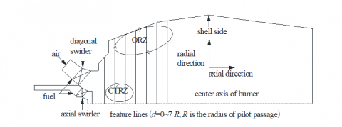
Figure 1. Schematic diagram of annular combustion chamber
2.1 Combustion chamber
The annular combustion chamber and hybrid combustor considered in this study is from an industrial gas turbine (see figure 1) [27]. The annular combustion chamber is made up of a hub with a structure of a cyclotron and an outer shell with two horizontally middle plane structures which is beneficial for installation [27]. Design of annular combustion chamber is beneficial for compacting the structure of the combustion chamber, reducing cooling area and uniform the distribution of outlet gas temperature [27, 28]. Ceramic insulation tiles are mounted on the wall of combustion chamber to reduce cooling air quantity [28]. 24 hybrid combustors are mounted around the circumferential direction of this combustion chamber, the structure of which is shown in figure 1. Advantages of flame stability of the diffusion flame and a lean premixed flame are combined and provide premixed Dry-Low-NOx (DLN) combustion [29]. Pilot fuel nozzles are mounted in the center of the hybrid combustor [30]. Axial swirler and diagonal swirler are arranged concentrically at outer of the pilot fuel nozzle with 8 and 24 vanes respectively. Flow rate and inlet pressure of fuel gas is 0. 55 kg/s and 2. 36 MPa [30]. Almost 6 % of the fuel gas is injected from pilot fuel nozzles [28]. While the rest is injected via premixed passage and mixes with combustive air before reaching the combustion chamber [31]. Inlet pressure of combustive air is approximately 1. 63 MPa [30]. Most of the combustive air is injected through diagonal swirler, and the rest through axial swirler. Vane angles of axial swirler and diagonal swirler are approximately 20° and 70° [30]. Global equivalence ratios of pilot passage stream and premix passage stream are 0. 36 and 0. 53 [30]. Detail structure of the annular combustion chamber and hybrid combustor also can be found in reference [30].
2.2 Numerical simulations
Due to the on-linear nature of large scale energetic motions and linear nature of small scale energetic motions, large scale energetic motions are directly resolved explicitly, while the sub-grid scale motions are modeled in LES approach [29]. A Favre filter is applied to the conservation equations of mass, momentum and energy yields [22]. Filtered conservation equations of mass, momentum and energy are shown as follows:
$\frac{\partial \overline{\rho}}{\partial t}+\frac{\partial\left(\overline{\rho} \overline{u}_{i}\right)}{\partial x_{i}}=0$(1)
$\frac{\partial\left(\overline{\rho} \overline{u}_{i}\right)}{\partial t}+\frac{\partial\left(\overline{\rho} \tilde{u}_{i} \tilde{u}_{j}+\overline{p} \delta_{i j}\right)}{\partial x_{j}}=\frac{\partial\left(\overline{\tau}_{y}+\overline{\tau}_{y}^{s g s}\right)}{\partial x_{j}}$(2)
$\frac{\partial(\overline{\rho} \overline{E})}{\partial t}+\frac{\partial\left((\overline{\rho} \overline{E}+\overline{p}) \overline{u}_{i}\right)}{\partial x_{j}}=\frac{\partial}{\partial x_{i}}\left(\overline{u}_{j} \overline{\tau}_{i j}+\lambda \frac{\partial \overline{T}}{\partial x_{i}}-H_{i}^{\mathrm{sgs}}+\sigma_{i}^{\mathrm{sgs}}\right)$(3)
where $\tau_{i j}^{s g s}$ is the sub-grid scale stress tensor determined by the dynamic version of the Smagorinsky-Lilly model, $H_{i}^{s g s}$ is the sub-grid scale flux of energy and $\sigma_{i}^{s g s}$is the sub-grid viscous diffusion term [25].
$\tau_{i j}^{\mathrm{sgs}}=-2 \mu_{s} \overline{S}_{i j}+1 / 3 \tau_{k k} \delta_{i j}$(4)
There are three main sub-grid scale combustion models provided in CFD code of ANSYS FLUENT, which are Laminar Finite Rate, Finite Rate /Eddy Dissipation and Eddy Dissipation Concept model [1, 5]. In this study, the Finite Rate /Eddy Dissipation model are used in LES approach where the rate of Arrhenius and eddy dissipation are calculated simultaneously, and chose the smaller one as the net reaction rate [1, 5]. Turbulent combustion models used in LES approach are often the direct extensions of RANS [31]. GRI-Mech CH4/air reaction mechanisms consist of 53 species and 325 step mechanisms, and the amount of computational resources is still too large for most practical applications [21]. In this study, CH4/air combustion is modelled by 4 step reaction mechanisms consisting of 6 species[27]. Reaction mechanisms and kinetic rate data are shown in Table 1.
Table 1. 4 step reaction mechanisms and kinetic rate data
|
Reaction mechanisms |
Kinetic rate(mol·m-3·s-1) |
|
CH4+0. 5O2=CO+2H2 |
R1=7. 82·1013e-30000/RT[CH4]0. 5[O2]1. 25 |
|
CH4+H2O=CO+3H2 |
R2=3·1013e-30000/RT[CH4][H2O] |
|
H2+0. 5O2= H2O |
R3=1. 21·1018e40000/RT[CO]0. 25[H2O]1. 5 |
|
CO+H2O=CO2+H2 |
R4=2. 75·1012e-20000/RT[H2] [O2] |
NOx modeling is executed as a post processing task after the calculation convergence of gas flow and combustion calculations. Total NOx emission consists of thermal NOx and prompt NOx. Fuel NOx is not modelled because nitrogen-containing organic compounds are not included in gas fuel [32]. Thermal NOx is generated from the reaction of N2 with O2 in the regions with high temperatures [33]. Formation of thermal NOx is simulated using the a simplified formation rate of thermal NOx is given by [33]:
$\frac{d|N O|}{d t}=2 k_{1}\left|N_{2} \| O\right|$(5)
For hydrocarbon combustion, formation of prompt NOx is simulated using a simplified formation rate of prompt NOx mechanism [34]:
$\frac{d|N O|}{d t}=C \frac{W^{1+b}}{\rho^{1+b}}\left|O_{2}\right|^{b}\left|N_{2}\right|\left|C_{x} H_{y}\right| \exp \left(-\frac{E_{a}}{R T}\right)$(6)
where C=6. 4×10⁶ s-1, Ea=3. 038×106 J/kmol and b=0. 5 [34].
In this study, modeling and mesh generation is solved with computational fluid dynamics (CFD) pre-processing software code Gambit. Rationality of the mesh division affects the solving speed, convergence and the precision of numerical solution. The annular combustion chamber is periodical along its circumferential direction [31]. In consequence, the computational domain only includes 1/24 of the real combustion chamber and its combustor [27]. Finite grid system is shown in figure 2. Considering the complexity of the computational domain, a structured multi-grid generation method is applied to achieve high quality hexahedral mesh of whole computational domain. The calculation domain is divided into two major parts which are the hybrid combustor and combustion chamber. Major structure of combustor is included in calculation domain [27]. However, the detailed swirlers are not included to achieve for high quality hexahedral mesh and reduce calculation time. The effects of swirlers vane angle on flow field are adjusted by setting the axial and radial components of velocity in ANSYS FLUENT code. The same simplified method also adopted by Tiribuzi et al. [27] and Gabriel et al. [28]. Local mesh encryption method have been used in the neighborhood of the combustor and sidewall of combustion chamber in order to improve calculation accuracy [21]. Relatively larger mesh is generated in the region near the exit of the combustion chamber to control the grid number of computer region and thus reduce the numerical calculations [21]. The calculation domain is consists with approximately 1,092,866 structured hexahedral mesh grids which is finer than that of Tiribuzi et al. [27] and Gabriel et al. [28].
Figure 2. Schematic diagram of grid structure
As aforementioned, the diagonal swirler vane angles of this hybrid combustor is approximately 20° in reference [30]. Swirler vane angles are increased to approximately 35° in reference [27] , with the same type of gas turbine. In this study, four different combustion cases have been selected in order to estimate the effects of diagonal swirler vane angle on combustion dynamic and NOx formation characteristic inside the combustion chamber which are 20°, 25°, 30° and 35° respectively (from Case 1 to Case 4). For the above cases, the same loads is given, flow rates of fuel gas and pilot fuel percentage are 0. 55 kg/s and 6 % [28]. Global equivalence ratios of pilot passage stream and premix passage stream are 0. 36 and 0. 53 [27]. Furthermore, both of temperatures of fuel gas and combustive air are set to 283 K. Time integration and iterative calculations for each time step are set as 2×10⁻⁶ s and 20 respectively. To study the changing process of premix combustion in 0. 5 second, the total number of time steps is about 250,000, for each case examined.
2.3 Validation of the numerical simulations
LES approaches with 4 step reaction mechanisms on the flow field, temperature distribution and pressure oscillations have been verified by Tiribuzi et al. [27] and Gabriel et al. [28]. The objective here is to verify whether the LES approach can bring a relevant answer for the coherent structure of vortex core, combustion dynamic and NOx formation characteristics which are also the mainly concerns in this paper. The coherent structure of vortex core under iso-thermal condition which visualized by a pressure iso-surface with the static pressure of about 1,579,000 Pa is similar to the numerical results by Selle et al. [35] with the similar combustor (see figure 8). Combustion instability inside the combustion chamber can generally be classified by the pressure oscillations [1]. In this study, vertex average of pressure is obtained near the hybrid combustor exit which is then resolved by Fourier transform. The LES calculated dominant frequencies of α=35° is 210 Hz which is in good agreement with the calculated results by Tiribuzi et al. [27]. Because the complexity of annular combustion chamber and hybrid combustor, detailed measurements inside the combustion chamber are usually unavailable [27]. In consequence, the LES calculated results are validated against experiments results of NOx emission under different fuel preheat temperature from reference [30]. For all the above cases, loads, pilot percentage and global equivalence ratios are consistent with Case 1 to Case 4, with the same type of gas turbine. Preheat temperatures of fuel gas are set as 283 K (Case 1), 453 K and 473 K, with the same combustive air temperature of 283 K. Flow rates of fuel gas decreases with the increasing of preheat temperatures which are 0. 55 kg/s (Case 1), 0. 542 kg/s and 0. 541 kg/s to keep the constant of thermal power. The comparison of LES calculated and experiment results are shown in figure 3. It is clear that the LES calculated results are in good agreement with that of the experiments, with maximum error of 3. 3 % [30]. Emissions of NOx decreases with the increasing of fuel gas preheat temperature. Good agreement between predicted and experiments results implies the LES approach is reasonable for studying the combustion dynamic and NOx formation characteristic inside the combustion chamber. Detail experiments results also can be found in reference [30].
Figure 3. Comparison of predicted results with experiments results (mg·m-3)
3.1 Effects on flow field
Figure 4 presents the instance axial velocity distributions in the center cross-sections of the combustor inside the combustion chamber, for all cases examined. Fresh incoming fuel/oxidant streams enter into the combustion chamber through the axial swirler and diagonal swirler arranged concentrically at outer of the pilot fuel nozzle which form two swirling flows with different axial and azimuthal velocities inside the combustion chamber [3]. Under the influence of centrifugal forces, the swirling flow sudden expansion and merge to form a wide cone inside the combustion chamber where the main flow is located. In consequence, sufficiently degree of adverse pressure gradient is formed which induces a central toroidal recirculation zone (CTRZ) in vicinity to the centerline of combustor [3]. Boundary of CTRZ extends to the exit of the hybrid combustor. Heat and active chemical species recirculate to the root of the flame which directly heat and ignite the incoming fuel/oxidant streams and thus improve flame stabilization [4, 5]. In the wake of the sudden expansion, two outer recirculation zones (ORZs) formed near the sidewall of combustion chamber [4, 5]. In consequence, three shear layers are located between the CTRZ, inflows and ORZs [4, 5]. It is clear that the width of CTRZ increases with the increasing of the flow distance due the expansion of main flow. The azimuthal velocity increases with the increasing of swirler vane angle which enlarges the expanding angle of main flow. In consequence, the magnitude of CTRZ increases with the increasing of swirler vane angle, while the magnitude of ORZs are the opposite, for all cases examined.
Figure 4. Instance axial velocity distribution in the center cross-sections of burner (m·s-1)
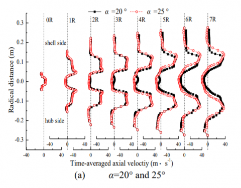
To obtain more accurate results, figure 5 presents the radical distributions of time-averaged radial velocity in different feature lines of center cross-sections of the combustor inside the combustion chamber, for all cases examined. The distances of different feature lines are range from 0 R to 7 R from pilot passage exit, where R is the radius of pilot passage (see figure 1) [28]. It is clear that the incoming fuel/oxidant streams from the axial swirler and diagonal swirler form two peak velocities on the each side of combustion chamber which is diminish with the increasing of axial distance, while distance between them is the opposite due the expansion of main flow, for all cases examined. The inner peak velocity disappears in the downstream of the flow field due the merge of swirling flows. There are regions with negative-velocity in vicinity to the centerline of combustor and sidewall of combustion chamber which are CTRZ and ORZs respectively [28]. Borderlines connecting points with zero velocity is usually defined as the borders of recirculation zone which is often used in many studies to compare the structure of recirculation zone inside the combustion chamber [28]. The magnitude of CTRZ increases with increasing of axial distance, while the reverse flow velocity is the opposite, for all cases examined. The magnitude of CTRZ increases with the increasing of swirler vane angle. For example, the width of CTRZ increases from 0. 097 m to 0. 11 m in the feature lines of 3 R, when the vane angle increases from 20° to 35°. Furthermore, the magnitude of ORZs decreases with the increasing of swirler vane angle. However, the decreasing amplitude decreases with the increasing of swirler vane angle due to the confinement of combustion chamber.
Figure 5. Time-averaged axial velocity distribution along different feature lines (m·s-1)
3.2 Effects on temperature distribution
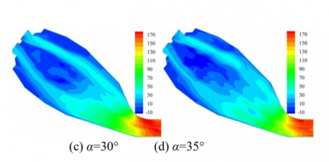
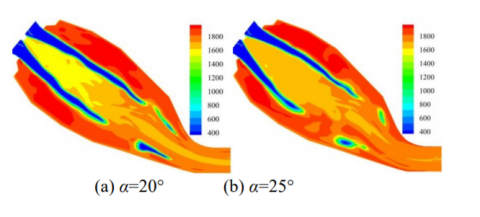
Figure 6 presents the instance flame temperature distributions in the center cross-sections of the combustor inside combustion chamber, for all cases examined. Compare figure 4 with figure 6, it is clear that this flame behavior strongly correlate with the distribution of recirculation zones inside the combustion chamber [4]. A central core of hot gases and combustion products extends to the exit of the combustor which could directly heat and ignite the incoming fuel/oxidant streams and thus establish a firm aerodynamic base for ignition and combustion of fuel gas [4]. Because of the relatively lower global equivalence ratio of pilot passage stream, excess air supplied in pilot fuel stream dilutes the flame temperature near the exit of pilot fuel nozzle. In lean premixed combustion, fuel gas and air are premixed to avoid the formation of stoichiometric regions inside the combustion chamber [4]. In consequence, flame temperature is relatively lower near the centreline of combustor. Because the exit of ORZs, recirculation of hot gases and combustion products improves the flame temperature in vicinity to the sidewall of combustion chamber where the peak flame temperature of the combustion chamber is located, for all cases examined. The magnitude of CTRZ increases with the increasing of swirler vane angle which increases the reverse flow velocity and back flow of hot gases and combustion products and thus improve the temperature of flame in vicinity to the combustor. Increase the swirler vane angle also compresses the magnitude of ORZs which decreases the peak temperature inside the combustion chamber.
Figure 6. Instance flame temperature distribution in the center cross-sections of burner (K)
Figure 7 presents the radial distributions of time-averaged flame temperature along different feature lines in the center cross-sections of the combustor inside the combustion chamber, for all cases examined. Although instantaneous flame temperature distributions are asymmetry in vicinity to the central of combustor, the time-average flame temperature in different axial cuts appears to be more symmetrical along the centerline of combustor, for all cases examined. The flame is relatively lower in vicinity to the CTRZ, and regions with higher flame temperature seem persist to ORZs. Increase of diagonal swirler vane angle enlarges the divergence angle of flame. In consequence, flame temperature near the centreline of combustor slightly increases with increasing of vane angle. The time-average flame temperature near the centerline of combustor is increase from about 1600 K to 1720 K, with growth of 120 K, when the vane angle increases from 20° to 35°. However, peak flame temperature and regions with high temperature in vicinity to sidewall of combustion chamber is the opposite, for all cases examined. When the temperature exceeds 1800 K, the increase of temperature will greatly enhance the formation process of thermal NOx according to Zeldovich mechanisms. In consequence, increase of diagonal swirler vane angle to decrease peak flame temperature near the sidewall of combustion chamber is beneficial for controlling the emission of NOx inside the combustion chamber. However, the decreasing amplitude of ORZs and peak temperature inside the combustion chamber decreases with the increasing of swirler vane angle due to the confinement of combustion chamber. In consequence, further increase the diagonal swirler vane angle will have relatively smaller impacts on compressing the NOx emission.
Figure 7. Time-averaged temperature distributions along different feature lines (K)
3.3 Effects on vortex core and combustion dynamic
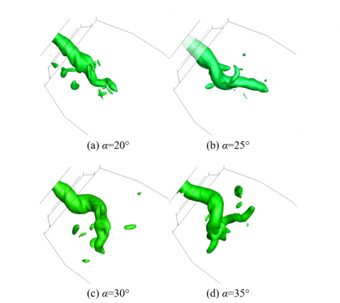
In order to counteract on the centrifugal force generated by azimuthal velocity, a low-pressure area formed in vicinity to the coherent structure of vortex core [1]. Figure 8 shows the coherent structure of vortex core under iso-thermal condition which visualized by a pressure iso-surface with the static pressure of about 1,579,000 Pa. It is clear that the overall structures of vortex cores are similar to each other which align initially with the centerline of the combustor in the upstream of the flow field and then undergoes the off-axis motion at the stagnation point of the recirculating flow before crush into smaller vortex [21]. The coherent structure of vortex core is correlated with structure of the shear layer regions [1, 2]. For α=20°, the stagnation point of the recirculating flow is located apart from the exit of combustor and the vortex core only undergoes the lowest amplitude off-axis motion due to the weakest centrifugal force generated by swirling flow [21]. Increase the swirler vane angle rise azimuthal velocity and the expanding angle of main flow which enlarge the magnitude of the CTRZ and thus the coherent structure of vortex core. The stagnation point of the recirculating flow move upstream and coherent structure of vortex core exhibit the largest off-axis motion for α=35°.
Figure 8. Structure of PVCs visualized by a pressure iso-surface
Combustion instability can generally be classified by large amplitude pressure oscillations inside the combustion chamber [1]. Large Eddy Simulation (LES) has already proved its ability to study the pressure oscillations and frequencies of turbulent flames in many studies [43]. In this study, vertex average of pressure is obtained near the hybrid combustor exit. Stable oscillation patterns which sustained with well-defined frequency are obtained after run for a sufficiently long time [1]. Figure 9 presents the time series of pressure fluctuations at different times, for all cases examined. Compare figure 8 with figure 9, it is clear that the difference of vortex structures exert a significant influence on the combustion process and thus the pressure fluctuations by modulating the mixing processes among fuel, air, and hot combustion products [22]. As expected, lowest oscillations amplitude of pressure are observed in the low diagonal swirler vane angle with α=20°. The oscillations amplitude of pressure increases with increasing of diagonal swirler vane angle. This phenomenon occurs firstly because increase the diagonal swirler vane angle result in smaller velocity disturbance in the radial direction and thus lead to relatively large oscillations amplitude of pressure [22]. Furthermore, heat release region is relatively larger under smaller diagonal swirler vane angle, and the acoustics dissipation of combustion chamber decrease the oscillations amplitude of pressure. As the diagonal swirler vane angle increases, heat release regions extent to the exit of combustor and thus induces larger amplitude oscillations in static pressure field. Figure 10 presents the pressure spectra, for all cases examined. The pressure spectra are resolved by Fourier transform. Dominant frequencies of α=35° is 210 Hz which is in good agreement with the numerical results by Tiribuzi et al. [27]. Increase of diagonal swirler vane angle has relatively smaller impact on dominant frequencies comparing to that of pressure amplitude. When the ratio of $\Delta p / \overline{p}$ is below 5 %, is defined as stable combustion, where $\overline{p}$ is the mean pressure of the combustion chamber. The mean pressures of combustion chamber are approximately 1. 62 MPa, when the vane angle increases from 20° to 35°. Although the amplitude of pressure oscillations increases with increasing of swirler vane angle, the ratio of $\Delta p / \overline{p}$ is still much lower than 5 % and the phenomenon of the combustion instability does not occur for all cases examined which indicated the introduciton of pilot diffusion flame effectivly compresses the occurrence of combustion instability.
Figure 9. Pressure oscillations at different times (Pa)
Figure 10. Fourier transform of pressure (Hz)
3.4 Effects on NOx formation
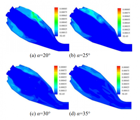
Figure 11 presents the instance NOx formation rate distributions in the center cross-sections of the combustor inside the combustion chamber, for all cases examined. Comparing figure 6 and figure 11, it is clear that the distribution of NOx formation rate is significantly associated with distribution of recirculation zones and region with high flame temperature inside the combustion chamber. Excess of combustive air supplied in pilot fuel streams dilutes the flame temperature, and thus control the NOx formation near the exit of pilot fuel nozzle. Because the combustion zone is operated with excess air, flame temperature and NOx formation rate is relatively lower near the centerline of combustor. In consequence, increase of the vane angle has relatively smaller impact on NOx formation rate in those regions. Because the recirculation of hot gases and combustion products in ORZs, the regions with peak flame temperature and NOx formation rate are located in vicinity to sidewall of combustion chamber. Increase of the vane angle effectively control the peak flame temperature and formation rate of NOx inside the combustion chamber. Furthermore, the uneven distribution of flame temperature leads to the uneven distribution of NOx formation. The formation regions of NOx in the shell side are larger than that of hub side inside the combustion chamber, for all cases examined.
Figure 11. Instance NOx formation rate distribution in the center cross-sections of burner (kmol·m-3·s-1)
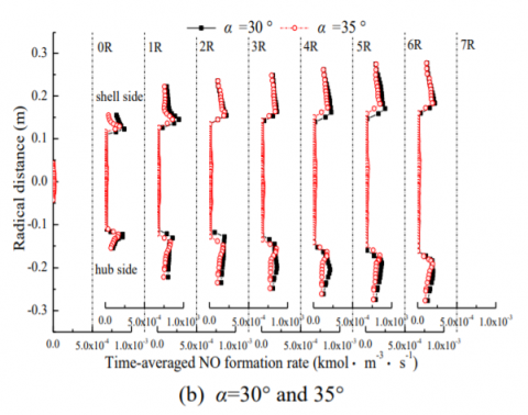
Figure 12 presents the radical distributions of mean NOx formation rate along different feature lines in the center cross-sections of the combustor inside the combustion chamber, for all cases examined. Comparing figure 7 and figure 12, the mean flame temperature near the centerline of combustor is much lower than 1800 K, while the peak temperature of flame is located in vicinity to sidewall of combustion chamber due to the recirculation of hot gases and combustion products in outer recirculation zones (ORZs). Higher flame temperature enhances the formation process of NOx in those regions due to the Zeldovich mechanisms. It is clear that the formation rate of NOx formation in vicinity to sidewall of combustion chamber decreases with the increasing of vane angle. Peak NOx formation rate decreases from 3. 2 e-4 kmol·m-3·s-1 to 1. 94 e-4 kmol·m-3·s-1 in shell side and 2. 5 e-4 kmol·m-3·s-1 to 1. 92 e-4 kmol·m-3·s-1 in hub side, when the vane angle increases from 20° to 35°. Figure 13 presents the predicted results of mean NOx emission at different swriler vane angles, for all cases examined. It is clear that increase of diagonal swirler angle decrease the emission of NOx. Increasing diagonal swirler angle from 20° to 35°, the LES calculated results of NOx emission is decrease from 52. 8 mg·m-3 to 38. 9 mg·m-3, with a drop of 26. 3 %. However, the decreasing amplitude of NOx emission decreases with the increasing of diagonal swirler angle. In consequence, proper adjusting swirl vane angle to control peak flame temperature and regions with high flame temperature is an effective mean to control the emission of NOx inside the combustion chamber. However, further increase the diagonal swirler vane angle will have relatively smaller impacts on compressing the NOx emission due to the confinement of combustion chamber.
Figure 12. Time-averaged NOx formation rates distribution along different feature lines (kmol·m-3·s-1)
Figure 13. Predicted results of mean NOx emissions at different vane angles (mg·m-3)
The characteristics of diagonal swirler vane angle on combustion dynamic and NOx formation have been numerically investigated using a three-dimensional full compressible LES approach. The predicted results show that increase the swirler vane angle enlarges the coherent structure and off-axis motion of vortex core which result in larger oscillations amplitude of pressure inside the combustion chamber. Increase the diagonal swirler vane angle result in smaller velocity disturbance in the radial direction and thus lead to relatively large oscillations amplitude of pressure. Furthermore, heat release region is relatively larger under smaller diagonal swirler vane angle, and the acoustics dissipation of combustion chamber decrease the oscillations amplitude of pressure. As the diagonal swirler vane angle increases, heat release regions extent to the exit of combustor and thus short the length of flame which induce larger amplitude oscillations in static pressure field. Because the combustion instability usually occurs in the condition of lean premixed combustion, and can be suppressed in diffusion flame, the phenomenon of combustion instability does not occur when the vane angle increases from 20° to 35°. Formation rate of NOx is relatively lower in pilot diffusion flame near the exit of hybrid combustor, because excess air contained in pilot fuel stream dilutes the flame temperature. Regions with peak flame temperature and maximum rate of NOx located in vicinity to the sidewall of the combustion chamber especially in the shell side due to the recirculation of hot gases and combustion products in the outer recirculation zones (ORZs). Magnitude of the ORZs decreases with the increasing of vane angle. In consequence, proper increase of diagonal swirler vane angle to compress the recirculation of hot gases and combustion products in ORZs is an effective mean to control peak flame temperature and NOx emission for this hybrid industrial combustor. However, further increase the diagonal swirler vane angle will have relatively smaller impacts on compressing the NOx emission due to the confinement of combustion chamber.
Project Supported by Fundamental Research Funds for the Central Universities (No. 2014ZZD04 and 2014XS17)
|
CFD |
Computational Fluid Dynamics |
|
CTRZ |
Central Toroidal Recirculation Zones |
|
DNS RANS |
Direct Numerical Simulations thermal Reynolds Average Navier-Stokes |
|
ISL LES ORZ OSL SGS |
Inner Shear Layer Large Eddy Simulations Outer Recirculation Zones Outer Shear Layer Sub Grid Scale |
[1] Y. Huang and V. Yang, “Dynamics and stability of lean-premixed swirl-stabilized combustion,” Progress in Energy and Combustion Science, vol. 35, pp. 293-364, 2009. DOI: 10.1016/j.pecs.2009.01.002.
[2] H. Zeinivand and F. Bazdidi-Tehrani, “Influence of stabilizer jets on combustion characteristics and NOx emission in a jet-stabilized combustor,” Applied Energy, vol. 92, pp. 348-360, 2010. DOI: 10. 1016/j.pecs.2012.04.004.
[3] D. M. Kang and F. E. C. Culick, “Combustion dynamics of a low-swirl combustor. Combustion and Flame, vol. 151, pp. 412-425, 2007. DOI: 10. 1016/j.combustflame.2007.07.017.
[4] S. Tanaka and M. Shimura, “DNS of turbulent swirling premixed flame in a micro gas turbine combustor,” Proceedings of the Combustion Institute, vol. 33, pp. 3293-3300, 2010. DOI: 10.1016/j.proci. 2010.07.034.
[5] N. Syred, “A review of oscillation mechanisms and the role of the precessing vortex core (PVC) in swirl combustion systems,” Progress in Energy and Combustion Science, vol. 32, pp. 93-161, 2006. DOI: 10.1016/j.pecs.2005.10.002.
[6] Y. Li and R. Li, “Combustion characteristics of a slotted swirl combustor: An experimental test and numerical validation,” International Communications in Heat and Mass Transfer, vol. 66, pp. 140-147, 2015. DOI: 10.1016/j.icheatmass transfer.2015.05.021.
[7] Guo Hongtao and Li Guoshuai, “Numerical simualtion research on the transonic aeroelasticity of a high-aspect-ratio wing,” International Journal of Heat and Technology, vol. 33, no. 4, pp. 173-180, 2015. DOI: 10.18280/ijht.330422.
[8] Linlin Liu and Chuliang Wan, “CFD simulation and structuer optimization of the hot-air drying oven of a gravuer printing machine,” International Journal of Heat and Technology. 33(4), pp. 197-202, 2015. DOI: 10.18280/ijht.330426.
[9] Carla Balocco and Giuseppe Petrone, “Thermo-fluid dynamics analysis and air quality for different ventilation patterns in an operating theater,” International Journal of Heat and Technology, vol. 33, no. 4, pp. 25-32, 2015. DOI: 10.18280/ijht.330404.
[10] S. T., “On stationary and traveling vortex breakdown,” Journal of Fluid Mechanics, vol. 45, pp. 545-559, 1971. DOI: 10.1017/S0022112071000 181.
[11] S. T., “Vortex breakdown in swirling conical flows,” AIAA Journal, vol. 9, pp. 1792-1799, 1971. DOI: http://dx.doi.org/10.2514/3.49981.
[12] L. S., “Vortex stability and breakdown: survey and extension,” AIAA Journal, vol. 22, pp. 1192-1196, 1984. DOI: 10.2514/3.8761.
[13] L. S. and Faler J., “An experimental map of the internal structure of a vortex breakdown,” Journal of Fluid Mechanics, vol. 86, pp. 313-335, 1977. DOI: 10.1017/S0022112078001159.
[14] C. F. Silva and M. Leyko, “Assessment of combustion noise in a premixed swirled combustor via Large-Eddy Simulation,” Computers & Fluids, vol. 78, pp. 1-9, 2010. DOI: 10.1016/j.compfluid.2010.09.034.
[15] Y. A. Eldrainy and K. M. Saqr, “CFD insight of the flow dynamics in a novel swirler for gas turbine combustors,” International Communications in Heat and Mass Transfer, vol. 36, pp. 936-941, 2009. DOI: 10. 1016/j.icheatmasstransfer.2009.06.013.
[16] J. Paik and F. Sotiropoulos, “Numerical simulation of strongly swirling turbulent flows through an abrupt expansion,” International Journal of Heat and Fluid Flow, vol. 31, pp. 390-400, 2010. DOI: 10.1016/ j.ijheatfluidflow.2010.02.025.
[17] E. C. Fernandes and M. V. Heitor, “An analysis of unsteady highly turbulent swirling flow in a model vortex combustor,” Experiments in Fluids, vol. 40, pp. 177-187, 2010. DOI: 10.1007/s00348-005-0034-4.
[18] P. M. Anacleto and M. V. Heitor & S, “Swirl flowstructure and flame characteristics in a model lean premixed combustor,” Combustion Science and Technology, vol. 175, pp. 1369-1388, 2010. DOI: 10.1080/ 00102200302354.
[19] M. R. Mafra and F. L. Fassani, “Influence of swirl number and fuel equivalence ratio on NO emission in an experimental LPG-fired chamber,” Applied Thermal Engineering, vol. 30, pp. 928-934, 2010. DOI: 10.1016/j.applthermaleng.2010.01.004.
[20] L. X. Zhou and F. Wang, “Simulation of swirling combustion and NO formation using a USM turbulence-chemistry model,” Fuel, vol. 82, pp. 1579-1586, 2003. DOI: 10.1016/S0016-2361(03)00089-9.
[21] G. Bulat and W. P. Jones, “NO and CO formation in an industrial gas-turbine combustion chamber using LES with the Eulerian sub-grid PDF method,” Combustion and Flame, vol. 161, pp. 1804-1825, 2014. DOI: 10.1016/j.combustflame.2013.12.028.
[22] G. Bulat and W. P. Jones, S., “Large eddy simulations of isothermal confined swirling flow in an industrial gas-turbine,” International Journal of Heat and Fluid Flow, vol. 51, pp. 50-64, 2015. DOI: 10.1016/j.ijheat fluidflow.2014.10.028.
[23] A. Andreini and B. Facchini, “Numerical analysis of a low NOx partially premixed burner for industrial gas turbine applications,” Energy Procedia, vol. 45, pp. 1382-1391, 2014. DOI: 10.1016/j.egypro.2014.01. 145.
[24] Y. A. Eldrainy and K. M. Saqr, “Large Eddy simulation and preliminary modeling of the flow downstream a variable geometry swirler for gas turbine combustors,” International Communications in Heat and Mass Transfer, vol. 38, pp. 1104-1109, 2011. DOI: 10.1016/ j.icheatmasstransfer.2011.05.017.
[25] L. Y. M. Gicquel and G. Staffelbach, “Large Eddy Simulations of gaseous flames in gas turbine combustion chambers,” Progress in Energy and Combustion Science, vol. 38, pp. 782-817, 2012. DOI: 10.1016/ j.pecs.2012.04.004.
[26] W. P. Jones and A. J. Marquis, “LES of a turbulent premixed swirl burner using the Eulerian stochastic field method,” Combustion and Flame, vol. 159, pp. 3079-3095, 2012. DOI: 10.1016/j.combustflame.2012.04. 008.
[27] S. Tiribuzi, “Very rough grid approach for CFD modelling of thermoacoustic oscillations inside an annular premixed combustor,” in Proc. the ASME Turbo Expo, 2006, pp. 11-21. DOI: 10.1115/GT2006-90055.
[28] G. Staffelbach, “Simulation aux grandes echelles et analyse acoustique de turbines´ a gaz industrielles multi-bruleurs”, Ph. D. dissertation, Dept. Elect. Eng., Institut National Polytechnique de Toulouse., Toulouse, France, 2006.
[29] A. X. Sengissen and A. V. Giauque, “Large eddy simulation of piloting effects on turbulent swirling flames. Proceedings of the Combustion Institute, vol. 31, pp. 1729-1736, 2007. DOI: 10.1016/j.proci. 2006.07.010.
[30] O. R. Darbyshire and C. W. Wilson, “CFD based analysis of burner fuel air mixing over a range of air inlet and fuel pre-heat temperatures for a Siemens v94. 3A gas turbine burner”, in Proc. the ASME Turbo Expo, 2006, pp. 709-714. DOI: 10.1115/GT2006-90944.
[31] S. Hermeth and G. Staffelbach, “LES evaluation of the effects of equivalence ratio fluctuations on the dynamic flame response in a real gas turbine combustion chamber. Proceedings of the Combustion Institute, vol. 34, pp. 3165-3173, 2012. DOI: 10. 1016/j.proci.2012.07.013.
[32] H. Y. Shih and C.-R. Liu, “A computational study on the combustion of hydrogen/methane blended fuels for a micro gas turbines,” International Journal of Hydrogen Energy, vol. 39, pp. 15103-15115, 2014. DOI: 10.1016/j.ijhydene.2014. 07.046.
[33] P. F. Werner Krebs and Bernd Prade, “Thermoacoustic stability chart for high-intensity gas turbine combustion systems. Combustion Science and Technology, vol. 174, pp. 99-128, 2007. DOI: 10.1080/00102 200208984089.
[34] L. Peng and J. Zhang, “Simulation of turbulent combustion and NO formation in a swirl combustor,” Chemical Engineering Science, vol. 64, pp. 2903-2914, 2009. DOI: 10.1016/j.ces.2009.03.001.
[35] L. Selle, “Compressible large eddy simulation of turbulent combustion in complex geometry on unstructured meshes,” Combustion and Flame, vol. 137, pp. 489-505, 2004. DOI: 10.1016/ j.combust flame.2004.03.008.