OPEN ACCESS
The inking system is an important part in the offset press, and a well performing inking system is essential for high quality printing. In this paper the Reynolds equation for ink transfer was deducted on the basis of the elastohydrodynamic lubrication theory. It establishes the relationship model between roller parameters such as pressure and ink thickness in roller gap by Hertz contact theory, so as to obtain the minimum thickness of the ink roller gap equation. As an object in Roland 700, through using computer simulation and modifying the ink transfer model, this study analyzes the influence of printing speed on the performance of ink transfer with the consideration of retention of ink in rollers gap.
Dynamic lubrication, Inking system, Transfer characteristic, Printing speed.
The role of the inking system is to rapidly and uniformly divide ink outputted by the ink bucket and to transfer the ink onto the block uniformly and properly. It is one of the important components of an offset printing machine, and a well performing inking system is essential for high quality printing. The inking system is a rather complex system in the various systems of an offset printing machine due to the diverse arrangement patterns of rollers and different parameters of rollers. The performance of the inking system will directly affect the quality of the printing products. The performance of the inking system is evaluated by static and dynamic indices. The quality characteristics are mainly measured by inking uniformity, the ink distributing coefficient, inking coefficient, ink storage coefficient, ink line number, ink transfer rate according to five static performance indices and response time, stability time and ink layer thickness uniformity three dynamic indices [1-2]. Globally, the dynamic performance of reactive ink is mainly used in computer simulation technology, and research has been conducted in this area within China, but it has not ye beed perfected [3-4]. In view of the present situation of the Chinese offset printing machine [5-8], a method of using $C++$ builder software was utilized to establish the simulation model of the system that describes the detail, the basic idea, design steps , and demonstrate some functions of the system [9].
Lubrication means adding a substance with small shearing resistance between the interacting surfaces with relative motions to reduce friction and decrease abrasion of materials. The substance added is called a lubricating agent. Ink used in offset printing acts as the printing medium and is transferred to the substrate, but the ink also plays the role of lubricating the rollers [10].
Rollers in the ink system of an offset printing machine are mainly rotated via gears and a fluid lubrication film is formed by hydrodynamic effect generated from relative motions of the contacting rollers. The contact surface is nearly non-heavy load linear contact friction, so it is considered as generalized elastohydrodynamic lubrication. There is not a large difference between the film thickness and the film thickness of corresponding hydrodynamic lubrication [11].
Hard rollers and soft rollers are arranged alternately in the inking system of an offset printing machine. Pressure between rollers belongs to the middle and low loads and the thickness of ink at the contact position of the rollers should be determined in advance [12]. In this paper, the average film thickness model of rollers was established through discretizing all rollers in 3mm×3mm and by using the deduction of the Грубин equation as the basis.
$h_{0}=1.95\left(a \eta_{0} U\right)^{8 / 11} R^{4 / 11}(E / W)^{1 / 11}$(1)
$\alpha$-pressure viscosity coefficient
$\eta_{0}$-the oil film viscosity environment
$R$-equivalent radius
$U$-entrainment velocity
$E$- equivalent elastic modulus
$W$-load per unit length
$h_{0}$-central oil film thickness ×
The equation contacts the Reynolds lubrication theory and the Hertz contact theory and provides the average ink thickness in the contact area, and the equation is applicable to heavy load lubrication conditions [12] [13].
2.1 Reynolds equation for ink transfer
Paper From a mathematical point of view, the solution of the Reynolds equation is the main content of fluid lubrication for the purpose of obtaining the distribution regularity of pressure on the fluid lubricating film. Under the isothermal condition, there are seven postulated conditions for the deduction of the Reynolds equation. The remaining two postulated conditions are added for the convenience of simulating calculation in this topic, totaling to nine postulated conditions as follows:
Figure 1 shows the force diagram along the $x$ direction with the fluid microelement obtained from the ink roller clearance The $x$-axis is in the width direction of ink roller contact, the $y$-axis is in the axial direction of ink roller contact and the $z$-axis is in the thickness direction of oil film. The velocities of the particle in the microelement along the coordinate axes of $x, y$ and $z$ are denoted by $u, v$ and $w$. From the force diagram of fluid microelement along the $x$ direction, the equilibrium equation can be formulated as follows:
Figure 1. Infinitesimal element fluid force
$p d y d z+\left(\tau_{x}+\frac{\partial \tau_{x}}{\partial z} d z\right) d x d y=\left(p+\frac{\partial p}{\partial x}\right) d y d z+\tau_{x} d x d y$(2)
From the postulated condition the Newton law of viscosity is substituted $\tau_{x}=\eta \frac{\partial u}{\partial z}$ and$\frac{\partial(\rho u)}{\partial x}+\frac{\partial(\rho w)}{\partial z}=0$ into the formula above. The Reynolds equation of ink transfer after simplification under postulated conditions is as follows:
$\frac{\partial}{\partial x}\left(\frac{\rho h^{3}}{\eta} \frac{\partial \rho}{\partial x}\right)=6 \frac{\partial}{\partial x}\left(\rho h U_{1}+\rho h U_{2}\right)$(3)
2.2 Hertz contact in ink system
The contact relation of two parallel rollers can be simplified into the relation between equivalent cylinders and the plane. It can be known from Hertz pressure that the larger the distance is from the center of contact width, namely, when the x-axis value is smaller than -b or larger than b, the smaller is the pressure, gradually decreasing to 0 [14]. It can be known from the extremum principle that must exist in the bearing area when. Then the equation is integrated and the boundary conditions are substituted into the equation to obtain the integration constant and further to obtain the first order Reynolds equation, namely:
$\frac{d p}{d x}=12 \eta U \frac{h-h^{*}}{h^{3}}$(4)
$U=\left(U_{1}+U_{2}\right) / 2$- entrainment speed of two opposite rollers;
$h$- gap function;
$p$-the pressure of the contact area;
$U$-Entrainment velocity;
2.3 Film thickness equation in gaps of rollers
The average ink film thickness in the contact area is calculated according to the deduction thought of the Грубин equation and the following three steps:
When ink exists between two rollers, the pressure at the contact half-width position is not increased rapidly while a certain transition curve exists to connect the pressure sections in the Hertz area due to hydrodynamic effects of the ink film. If the entrance pressure is set as$p_{x=-b}=p$, then the induction pressure here will be:
$q=\left(1-e^{-\alpha p^{\prime}}\right) / a$(5)
When the non-dimensional coordinate tends to $+\infty$, both $p$ and $q$ are 0. When the non-dimensional coordinate tends to the contact half-width at the entrance, it can be known from the above definition that $p$ is $p$ and $q$ is $q=\left(1-e^{-\alpha p}\right) /a$.
Then the relation $h_{0}=(4 / 3) h_{\min }$ between the average film thickness and the minimum film thickness is utilized and the non-dimensional boundary conditions are substituted into the above equation to obtain:
$\overline{q}=48\left(\frac{\overline{W}}{2 \pi}\right)^{1 / 2} \overline{U} \int_{1}^{+\infty} \frac{\left[(\sqrt{3}(\overline{x}-1)+1)^{2}-1\right]\left(1-\varepsilon_{\delta}\right)}{\left\{\overline{h}_{0}+\frac{4 \overline{W}}{3 \pi}\left[(\sqrt{3}(\overline{x}-1)+1)^{2}-1\right]\left(1-\varepsilon_{\delta}\right)\right\}}$(6)
$\varphi=\left\{\begin{array}{ll}{\frac{1}{(1-\lambda)^{2}}\left[2\left(1+\frac{2}{\lambda}\right)-\frac{4-\lambda}{\sqrt{1-\lambda}} \ln \frac{(1+\sqrt{1-\lambda})^{2}}{\lambda}\right]} & {\lambda<1} \\ {\frac{1}{(1-\lambda)^{2}}\left[2\left(1+\frac{2}{\lambda}\right)-\frac{4-\lambda}{\sqrt{\lambda-1}}\left(\pi-2 \operatorname{arctg} \frac{1}{\sqrt{\lambda-1}}\right)\right]} & {\lambda>1}\end{array}\right.$(7)
where:
$\varphi=0.26\left(\frac{\overline{W}^{-1.5}}{\overline{G} \overline{U}}\right)\left(1-e^{-0.08 \overline{G} \overline{W}^{-0.5}}\right)$, $\lambda=\pi\left(\frac{\overline{h_{0}}}{\overline{W}}\right)$
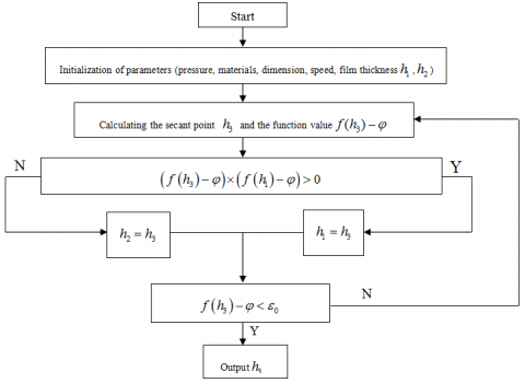
The solutions of equation (7) are the analytic solutions of the Reynolds equation obtained here. The values are substituted to obtain the minimum ink film thickness in the gaps of the rollers [16]. The solutions are calculated by using the secant method and the procedures are shown in Fig. (2).
Figure 2. Traces Calculation flowchart
3.1 Influences of roller’s dimension
Roland 700 HiPrint is a classical offset press made by Manroland Sheetfed GmbH, with excellent performance and high market share with the classical ink system as shown in Fig.(3). In Fig.(3), the inking roller is marked as red, which rapidly and uniformly divides ink outputted by the ink bucket and transfers the ink onto the blanket cylinder uniformly and properly. The damping roller is marked as blue which transfers the fountain solution onto the blanket cylinder.
The inking system of Roland 700 is shown in Fig. (3). The contact width of adjacent rollers is set at 3mm, the flexural modulus of the rubber roller (rubber) at $7.84 \times 10^{6} \mathrm{pa}$, the flexural modulus of the rubber roller (block) at $2.06 \times 10^{11}$pa, and the Poisson’s ratio of the rubber roller at 0.47. The environment viscosity of ink is set at 20, the pressure-viscosity coefficient at$2.2 \times 10^{-8} \mathrm{m}^{2} / \mathrm{s}$, and the entrainment speed of the roller at1.0 $\mathrm{m} / \mathrm{s}$. Under the situation of providing roller’s dimension, equivalent radius R of adjacent rollers, equivalent flexural modulus$E^{\prime}$, load parameter and material parameter can be determined. Equation (7) is solved to obtain the minimum ink film thickness in the contact area of adjacent rollers [17] [18].
Figure 3. Inking system of Roland 700
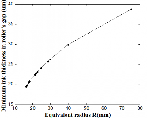
Figure 4. Influence of roller’s dimension
The minimum ink film thickness in the gaps of the rollers is relevant to the dimensions of adjacent rollers. The relation between the equivalent radius of the rollers and the minimum ink film thickness in the roller’s gaps is shown in Fig. (4) The larger the equivalent radius is, the larger is the thickness of ink film which can pass through the roller’s gaps.
This shows that, when other conditions are kept constant, the larger the dimension of rollers is, the more ink which can pass through roller’s gaps is.
3.2 Influences of pressure
Figure 5. Influence of roller’s pressure
If the diameter of two rollers is each 300mm, then the equivalent radius is 75mm and the entrainment speed of rollers is.
The roller contact width was changed to 3mm, 3.5mm, 4mm, 4.5mm and 5mm, respectively and the minimum ink thickness in the roller’s gap under different contact width was calculated. The results are shown in Fig. (5), showing that the larger the contact width of the rollers is, namely, the larger the unit length load is, the smaller is the minimum ink film thickness in roller’s gap.
3.3 Influence of printing speed
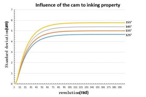
Figure 6. Influence of printing speed
According to data of the rollers in the inking system of the Roland 700 type offset printing machine, if definitions of material parameters are the same as above and contact width of adjacent rollers is 3mm, the contact width between rollers is 4mm. Combining the calculation model of the minimum ink film thickness in the roller’s gap in this chapter, simulation was carried out on inking characteristics of the inking system when the printing speed is 764r/h (0.2m/s), 3820r/h (1.0m/s), 6876r/h (1.8m/s) and 9932 r/h (2.6m/s), respectively, and the influences of printing speed on inking characteristics of the inking system was obtained, as shown in Fig. (6), in which (125 º), (135 º), (145º) and (155º) are change curves of average ink thickness on paper under corresponding printing speeds.
As shown in Fig. (6), the higher the printing speed is, the larger the ink thickness is on paper under the same number of revolutions of rollers due to an increase in ink passing the roller’s gap.
It can be known from comparing the ink thickness data under different printing speeds that average ink thickness on paper under different number of revolutions in different curves is increased gradually.
When the block roller rotates at 50 revolutions, the rate of change in ink thickness on paper under the speed of (125º), (135º), (145º) and (155º) is 0.1%, 0.4%, 0.6% and 0.9%, respectively. Therefore, the higher the printing speed is, the longer is the inking stabilization time.
In this paper, the relations model is established between roller parameters such as pressure and ink thickness in roller gaps by Hertz contact theory. The equation was solved through a program to obtain the minimum ink film thickness in roller’s gaps under given parameters and it studies the influences of different roller parameters, pressure on average film thickness in the roller’s gaps. The analysis yielded the following results. The larger the equivalent radius of rollers is, the larger is the ink film thickness in roller’s gap, and the larger the contact pressure of rollers is, the smaller is ink film thickness is in roller’s gap.
Finally, simulation analysis was carried out on the inking system of the Roland 700 type offset printing machine. The results showed that the larger the printing speed is, the larger is the inking stabilization time.
The authors gratefully acknowledge the support of the National Natural Science Foundation of China (Grant No.51375395), China Postdoctoral Science Foundation (2014M552484), Natural Science Foundation of Shaanxi Province (2014JM8334), Science Foundation of Shaanxi Educational Department (Natural Science 2013jk0996), and Science Foundation of Xi’an University of Technology (104-211106).
[1] Haiyan Zhang, Printing Machine Design, Beijing: Press of Printing Industry, 2006.
[2] Haiyan Zhang and Wei Zhang, “Computer simulation research on inking system design of offset press,” J. Packaging Engineering, 2003(5), pp. 51-53. DOI: 10.3969/ j.issn.1001-3563.2003.05.021.
[3] Shaoyan Tang, “Computer aided design and Simulation of offset printing machine,” Xi’an University of Technology, 1995.
[4] Fei Lu, Haiyan Zhang and Linlin Liu, “Study on the dynamic ink transfer rate of offset printing inking system,” J. Light Industry Machinery, Apr. 2011. DOI: 10.3969/ j.issn.1005-2895. 2011. 02. 010.
[5] Ziyou Bai and Shiwei Liu, “Study on dynamic simulation model of offset print inking roller,” J. Packaging Engineering, vol. 25, no. 3, pp. 159-160, 2004. DOI: 10.3969/j.issn. 1001- 3563. 2004.03.071.
[6] Jimei Wu and Qiumin Wu, “Research on ink flow ratio based on percentage of coverage of rotary offset press,” J.Packaging Engineering, vol. 27, no. 2, pp. 87, 89, 93, 2006. DOI: 10.3969/j.issn.1001-3563.2006.02.032.
[7] Linlin Liu, Zhengcheng Sun, Chuliang Wan and Jimei Wu, “Jet flow field calculation & mechanism analysis on hot-air drying oven based on RNG K-E model,” J. International Journal of Heat and Technology, vol. 33, pp. 77-82, 2015. DOI:10.18280/ijht.330111.
[8] Linlin Liu, Jian Liu, Xiaoyan Zhang and Shanshan Zheng, “Analysis and optimization of hot air drying device of a gravure printing machine based on fluid analysis,” J. Applied Mechanics and Materials, vol. 121, pp. 2517-2521, DOI: 2012.10.4028/www.scientific.net/AMM.121-126.2517.
[9] Ziyou Bai, “Study on simulation model of inking system,” J. Packaging Engineering, 2007. DOI: 10.3969/j.issn.1001-3563. 2007.02.029
[10] Leigang Bing, “Experimental study on EHL friction under big slide-roll ratio conditions,” Hefei University of Technology, pp. 25-40, 2008. DOI: 10.3321/j.issn: 1004-132X.2008.21.014.
[11] Shizhu Wen and Peiran Yang, Elastohydrodynamic Lubrication, Beijing: Tsinghua University Press, pp. 13-16, 1992.
[12] Pinkus O., Sternlicht B., Hydrodynamic Lubrication Theory, translated by Bearing Research Group of Xi’an Jiaotong University, Beijing: China Machine Press, pp. 165-78, 1980.
[13] Greenwood J. A., “An extension of the Grubin theory of elastohydrodynamic lubrication,” J. Journal of Physics D: Applied Physics, pp. 88-93, 1972. DOI: 10.0000/02664769723440
[14] Archard J. F. and Balin K. P., “Elastohydrodynamic lubrication-improvements in analytic solutions,” Archive: J. Proceedings of the institution of Mechanical Engineers, Part C: Mechanical Engineering Science vol. 200, no. C4, pp. 75-78, 1986. DOI: 10.1243/ PIME_PROC_1986_200_129_02
[15] Jinshan Kang, Hongyan Chu and Ligang Cai, “Modeling of ink transfer path based on inking system structure,” J. Packaging Engineering, vol. 31, no. 3, pp. 75-78, 2010.
[16] G. E. Morales-Espejel, “Central film thickness in time-varying normal approach of rolling elastohydrody-namicllly lubricated contact,” J. Drive System Technique, no. 6: 22-26, 2012.
[17] Chang’an Ding, Jun Zhu and Fuzhang Zhou, “Calculation of elastic fluid dynamics oil film thickness in wide range,” J. Bearing, no. 8, pp. 4-8, 2002. DOI:10.3969/j.issn.1000-3762.2002.08.002
[18] Yasheng Huang and Kangying Cheng, Light Printing System, Beijing: Printing Industry Press, pp. 115-120, 1990.