OPEN ACCESS
A study on the effects of Hall current, ion-slip and permeability on unsteady Magnetohydrodynamic Couette-Poiseuille flow within porous plates filled with porous medium in the presence of a moving uniform transverse magnetic field which is fixed relative to the moving porous plate is carried out. Flow within the channel is generated due to accelerated movement of the lower plate of the channel along x-axis and by an applied constant pressure gradient acting along x-axis. An exact solution of the governing equations is found by Laplace transform method. Numerical values of analytical solution for fluid velocity and that of shear stress at the moving porous plate of the channel are depicted for various values of pertinent flow parameters. It is noticed from the numerical result that, for the pure fluid regime, suction tends to enhance fluid velocity in the primary flow direction whereas injection has reverse effect on it. For the small permeable regime, suction tends to enhance fluid velocity in the primary flow direction in the upper half of the channel whereas injection has reverse effect on it.
Hall current, Ion-slip, Magnetic field, Permeability, Suction/injection. Hall current, Ion-slip, Magnetic field, Permeability, Suction/injection.
Magnetohydrodynamic (MHD) flows through purely fluid medium and porous medium have drawn attention of many researchers due to its diverse applications in geophysical, astrophysical, biological, agricultural and engineering problems. An electrically conducting fluid permeated by magnetic fields induces many electromagnetic phenomena viz. Hall effect, ion-slip effect, Ohmic heating etc. (Cramer and Pai [1]). Such phenomena may have considerable effect on heat and mass transfer flows and flow dynamics. Hall effect becomes significant when an ionized fluid with low density (plasma) is permeated by a strong magnetic field (Sato [2]). Hall effect is likely to be important in underground energy storage systems, magnetometers, Hall effect sensors and spacecraft propulsion. In addition, when the magnetic field is strong, the diffusion velocity of ions may not be negligible in an ionized fluid and phenomenon of ion-slip arises (Cramer and Pai [1]). In such cases, Hall and ion-slip currents are included in generalized Ohm’s law. Mittal et al. [3] presented a study on influence of Hall and ion-slip currents on two-dimensional MHD flow in the entrance region of a rectangular channel. Soundalgekar et al. [4] presented an analysis of the MHD Couette flow with heat transfer by taking Hall and ion-slip effects into account. Ram et al. [5] considered the combined effects of Hall and ion-slip currents on convective flow in a rotating fluid with oscillating wall temperature. Takhar and Jha [6] investigated the effects of Hall and ion-slip currents on MHD flow past an impulsively started plate in a rotating system. Attia [7] discussed the unsteady Couette flow of an electrically conducting fluid bounded by two parallel non-conducting porous plates taking Hall and ion-slip currents into consideration. Naroua et al. [8] analysed transient hydromagnetic partially-ionized heat generating gas dynamics flow with Hall/ion-slip effects in a rotating system using finite element method. Beg et al. [9] presented a theoretical study of unsteady MHD viscous Hartmann-Couette laminar flow and heat transfer in a Darcian porous medium with Hall current, ion-slip, viscous and Joule heating effects. Jha and Apere [10] analysed the influence of Hall and ion-slip currents on unsteady MHD Couette flow in a rotating system in the presence of a transverse magnetic field which is either fixed relative to the fluid or to the moving plate. Subsequently Jha and Apere [11] investigated time-dependent MHD Couette flow in a rotating system taking Hall and ion-slip currents into consideration. Recently Singh et al. [12] studied effects of Hall current and ion-slip on unsteady hydromagnetic generalized Couette flow in a rotating Darcian channel in the presence of a transverse magnetic field which is fixed relative to the fluid. The equation governing the fluid motion through a porous medium is based on Darcy’s law, which determine the drag force exerted by porous medium (Ingham and Pop [13]). MHD flows through porous medium may find applications in many biological and engineering problems viz. the movement of water, oil and natural gases in reservoirs, in filtration and water purification process, to study underground water sources and seepage of water in river beds etc. Chamkha [14] investigated steady laminar flow of two viscous, incompressible, electrically conducting and heat generating/absorbing immiscible fluids in porous and non-porous channels. Subsequently Chamkha [15] discussed unsteady laminar fully-developed hydromagnetic flow and heat transfer of an electrically conducting fluid and heat generating/absorbing fluid in a porous channel filled with porous medium. Makinde and Mhone [16] presented combined effect of transverse magnetic field and radiative heat transfer to unsteady flow of a conducting optically thin fluid through a channel filled with porous medium. Beg et al. [17] performed a numerical study of magnetohydrodynamic viscous plasma flow in a rotating porous medium with Hall current in the presence of an inclined magnetic field. Israel-Cookey et al. [18] analysed MHD free convection and oscillatory flow of an optically thin fluid bounded by two porous walls in a porous medium. Chauhan and Agrawal [19] presented a study on effects of Hall current on MHD Couette flow in a channel partially filled with a porous medium in the presence of an inclined magnetic filed in a rotating system. Singh and Mathew [20] presented the effects of permeability and suction/injection on an oscillatory free convective flow through a highly porous medium bounded between two infinite vertical porous plates. Singh and Pathak [21] considered the influence of Hall current and rotation on mixed convection MHD flow through a porous medium filled in a vertical channel in the presence of thermal radiation. Subsequently, Singh et al. [22] discussed the effect of Hall current on visco-elastic MHD oscillatory convective flow through a porous medium in a vertical channel with heat radiation. Recently Ahmed and Chamkha [23] investigated Hartmann-Newtonian radiating MHD flow for a rotating vertical porous channel merged in a Darcian porous regime. Seth et al. [24] discussed steady hydromagnetic class-II Couette flow through a porous medium with Hall current and rotation. Singh et al. [12] considered medium filled within horizontal parallel plates as porous medium in their problem.
The motive of the present investigation is to study the influence of Hall current, ion-slip and permeability on unsteady magnetohydrodynamic Couette-Poiseuille flow within porous plates filled with porous medium in the presence of a moving uniform transverse magnetic field which is fixed relative to the moving porous plate. The flow within porous plates filled with porous medium is generated due to movement of the lower plate along x-axis and by an applied constant pressure gradient acting along the x-axis. Two particular cases for the medium filled within the porous plates are considered i.e. (i) the case of small permeable regime and (ii) the case of pure fluid regime.
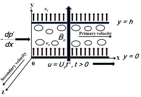
Consider cartesian coordinate system $(x, y, z)$ as frame of reference for unsteady laminar flow of a viscous incompressible electrically conducting fluid within two infinite porous plates $y=0$ and $y=h$ filled with porous medium and flow is permeated by a uniform transverse magnetic field $B_{0}$ applied along $y$-axis. The porous plates are parallel to $x z$-plane and $y$-axis is normal to the porous wall. Initially (when time $t \leq 0$) the whole system is at rest and suddenly (when time $t>0$) the lower porous plate starts to move with the velocity $U_{0} t^{n}$ along $x$-axis while the upper porous plate remains stationary. The flow within the porous plates filled with the porous medium is generated due to movement of the lower porous plate along $x$-axis and by an applied constant pressure gradient $-\partial p^{\prime} / \partial x$ along $x$-axis. Suction/injection occurs normal to the porous plates with a uniform transpiration velocity $v_{0}$($v_{0}>0$ for suction and $v_{0}<0$for injection). The electric field $\vec{E}=(0,0,0)$ because there is no applied or polarization voltage imposed on the flow-field. Also induced magnetic field produced by fluid motion is assumed to be negligible in comparison to applied one because the magnetic Reynold’s number $R_{m}=\sigma \mu_{e} U_{0} h<<1$ and fluid is partially ionized (Cramer and Pai [1]). All fluid flow characteristics except pressure will be function of y and t only because the porous plates are infinitely extended along x and z directions. The schematic diagram of the problem is presented in Figure 1.
Figure 1. The schematic diagram of the problem.
Under the above made assumptions the fluid velocity $\vec{V}$ and induced magnetic field $\vec{B}$ are represented by
$\vec{V}=\left(u, v_{0}, w\right)$ and $\vec{B}=\left(0, B_{0}, 0\right)$(1)
The general equation of motion for this fluid flow problem is given by
$\frac{\partial \vec{V}}{\partial t}+(\vec{V} . \nabla) \vec{V}=-\frac{1}{\rho} \nabla p^{\prime}+v \nabla^{2} \vec{V}+\frac{1}{\rho} \vec{J} \times \vec{B}-v \frac{\vec{V}}{k}$(2)
The generalized Ohm’s law for a moving conductor in account of Hall current and ion-slip is represented in the following form (Sutton and Sherman [25]) as
$\overline{J}=\sigma[\vec{E}+(\vec{V} \times \overline{B})]-\frac{B_{e}}{B_{0}}(\vec{J} \times \vec{B})+\frac{B_{e} B_{i}}{B_{0}^{2}}(\vec{J} \times \vec{B}) \overrightarrow{ \times B}$(3)
Use Eqs (1) and (3) in Eq (2), the equation of motion in component form are given by
$\frac{\partial u}{\partial t}+v_{0} \frac{\partial u}{\partial y}=-\frac{1}{\rho} \frac{\partial p^{\prime}}{\partial x}+v \frac{\partial^{2} u}{\partial y^{2}}$$-\frac{\sigma B_{o}^{2}}{\rho}\left[\frac{u\left(1+B_{i} B_{e}\right)+w B_{e}}{\left(1+B_{i} B_{e}\right)^{2}+B_{e}^{2}}\right]-\frac{v u}{k} $(4)
$0=-\frac{1}{\rho} \frac{\partial p^{\prime}}{\partial y}$(5)
$\frac{\partial w}{\partial t}+v_{0} \frac{\partial w}{\partial y}=v \frac{\partial^{2} w}{\partial y^{2}}+\frac{\sigma B_{o}^{2}}{\rho}\left[\frac{u B_{e}-w\left(1+B_{i} B_{e}\right)}{\left(1+B_{i} B_{e}\right)^{2}+B_{e}^{2}}\right]-\frac{v w}{k}$(6)
The initial and boundary conditions for the fluid motion are given by
$u=w=0 \qquad$ for $0 \leq y \leq h$ and $t \leq 0$(7)
$u=U_{o} t^{n}, w=0 \quad$ at $y=0$ for $t>0$(8)
$u=w=0 \qquad$ at $y=h$ for $t>0$(9)
Eq (4) is applicable when magnetic lines of force are fixed relative to the fluid. On the other hand, if the magnetic lines of force are also moving with the same velocity $U_{0} t^{n}$ as that of lower porous plate i.e. the magnetic lines of force are fixed relative to the moving lower porous plate, the relative motion should be must taken into account. In such a case, Eq (4) is replaced by the following equation
$\frac{\partial u}{\partial t}+v_{0} \frac{\partial u}{\partial y}=-\frac{1}{\rho} \frac{\partial p^{\prime}}{\partial x}+v \frac{\partial^{2} u}{\partial y^{2}} $$-\frac{\sigma B_{o}^{2}}{\rho}\left[\frac{u\left(1+B_{i} B_{e}\right)+w B_{e}-U_{o} t^{n}}{\left(1+B_{i} B_{e}\right)^{2}+B_{e}^{2}}\right]-\frac{v u}{k}$(10)
Eqs (10) and (6) subject to the initial and boundary conditions (7) to (9) represent mathematical model of the present physical problem.
Now it is required to find the solution of Eqs (10) and (6) subject to the initial and boundary conditions (7) to (9), for this purpose writing Eqs (10) and (6) in compact form, we obtain
$\begin{aligned} \frac{\partial q}{\partial t}+v_{0} \frac{\partial q}{\partial y} &=-\frac{1}{\rho} \frac{\partial p^{\prime}}{\partial x}+v \frac{\partial^{2} q}{\partial y^{2}} \\ &-\frac{\sigma B_{o}^{2}}{\rho}\left[\frac{\left\{\left(1+B_{i} B_{e}\right)-i B_{e}\right\} q-U_{0} t^{n}}{\left(1+B_{t} B_{e}\right)^{2}+B_{e}^{2}}\right]-\frac{v q}{k} \end{aligned}$(11)
where $q=u+i w$
The initial and boundary conditions in compact form are represented by
$q=0 \qquad$ for $0 \leq y \leq h$ and $t \leq 0$(12)
$q=U_{o} t^{n} \qquad$ at $y=0$ for $t>0$(13)
$q=0 \qquad$ at $y=h$ for $t>0$(14)
Eq (11) describe the general flow characteristic for Couette-Poiseuille flow between two infinite porous plates filled with the porous medium in the presence of a uniform transverse magnetic field. In order to describe the specific flow characteristics we consider the case when $n=1$ which corresponds to the accelerated motion.
Defining the following non-dimensional variables
$x^{*}=\frac{x}{h}, y^{*}=\frac{y}{h}, q^{*}=\frac{q}{U_{0}}, p^{*}=\frac{p^{\prime}}{\rho U_{0}^{2}}$ and $t^{*}=\frac{t U_{0}}{h}$(15)
After putting $n=1$ and using non-dimensional variables defined in Eq (15), Eq (11) and initial and boundary conditions (12) to (14), in non-dimensional form, become
$\frac{\partial q^{*}}{\partial t^{*}}+N_{t} \frac{\partial q^{*}}{\partial y^{*}}=R+\frac{1}{R_{e}} \frac{\partial^{2} q^{*}}{\partial y^{2}}$$\quad-\frac{H_{a}^{2}}{R_{e}}\left[\frac{\left\{\left(1+B_{i} B_{e}\right)-i B_{e}\right\} q^{*}-R_{1} t^{*}}{\left(1+B_{i} B_{e}\right)^{2}+B_{e}^{2}}\right]-\frac{q^{*}}{D_{a} R_{e}}$(16)
$q^{*}=0 \qquad$ for $0 \leq y^{*} \leq 1$ and $t^{*} \leq 0$(17)
$q^{*}=R_{1} t^{*}$ at $y^{*}=0$ for $t^{*}>0$(18)
$q^{*}=0 \qquad$ at $\quad y^{*}=1$ for $t^{*}>0$(19)
where $N_{t}=v_{0} / U_{0}$($N_{t}>0$ for suction and $N_{t}<0$ for injection) represents the mass of the fluid entering into the Darcian channel via the moving porous plate and coming out via the stationary porous plate, $R=-d p^{*} / d x^{*}$, $R_{e}=U_{0} h / v$ represents the relative strength of inertial force to the viscous force, $H_{a}^{2}=\sigma B_{0}^{2} h^{2} / \mu$ represents the relative strength of magnetic force to the viscous force,$D_{a}=k / h^{2}$ represents the relative permeability of Darcian channel and $R_{1}=h / U_{0}$.
The exact solution of Eq (16) subject to the initial and boundary conditions (17) to (19) are derived using Laplace transform method. Taking Laplace transform of Eq (16), boundary conditions (18), (19) and using initial condition (17), we transform Eq (16) and boundary conditions (18), (19) to the following equations
$\frac{d^{2} \overline{q^{*}}}{d y^{-2}}-N_{t} R_{e} \frac{d \overline{q}^{*}}{d y^{*}}-R_{e}\left(s+m_{4}\right) \overline{q^{*}}=-\frac{R_{1} R_{e} m_{1}}{s^{2}}-\frac{R R_{e}}{s}$ (20)
$\overline{q^{*}}=\frac{R_{1}}{s^{2}} \qquad$ at $y^{*}=0$(21)
$\overline{q^{*}}=0 \qquad$ at $y^{*}=1$(22)
where $\overline{q^{*}}(y, s)=\int_{0}^{\infty} e^{-s t} q^{*}(y, t) d t$, $s(s>0)$ being the Laplace parameter and
$m_{1}=\frac{H_{a}^{2}}{R_{e}\left[\left(1+B_{i} B_{e}\right)^{2}+B_{e}^{2}\right]}, m_{2}=B_{e} m_{1}$
Solving Eq (20) subject to the boundary conditions (21) and (22), the solution of Eq (20) is given by
$\overline{q}_{a}^{*}=\sum_{n=0}^{\infty}\left[\left(\frac{e^{-a \lambda_{1}}}{s^{2}}-\frac{e^{-b \lambda_{1}}}{s^{2}}\right)+(-1)^{n+1}\left\{\frac{m_{1}}{m_{4}}\left(\frac{e^{-c \lambda_{1}}}{s^{2}}+\frac{e^{-d \lambda_{1}}}{s^{2}}\right)\right.\right.$$-\left(\frac{m_{1}}{m_{4}^{2}}-\frac{R^{*}}{m_{4}}\right)\left(\frac{e^{-c \lambda_{1}}}{s}+\frac{e^{-d \lambda_{1}}}{s}-\frac{e^{-c \lambda_{1}}}{\left(s+m_{4}\right)}-\frac{e^{-d \lambda_{1}}}{\left(s+m_{4}\right)}\right) \} ]$$+\left\{\frac{m_{1}}{m_{4} s^{2}}-\left(\frac{m_{1}}{m_{4}^{2}}-\frac{R^{*}}{m_{4}}\right)\left(\frac{1}{s}-\frac{1}{\left(s+m_{4}\right)}\right)\right\}$ (23)
where
$a=2 n+y^{*}, b=2+2 n-y^{*}, c=n+y^{*}, d=n+1-y^{*}$,
$q_{a}^{*}=\frac{q^{*}}{R_{1}}=u_{a}^{*}+i w_{a}^{*}, X_{2}=\frac{N_{t}^{2} R_{e}}{4}+m_{3}$,
$\alpha, \beta=\frac{1}{\sqrt{2}}\left[\left\{X_{2}^{2}+m_{2}^{2}\right\}^{1 / 2} \pm\left(X_{2}\right)\right]^{1 / 2}, \quad R^{*}=\frac{R}{R_{1}}$,
$p=\alpha-i \beta, \lambda_{1}=\left(N_{t} R_{e} / 2\right)+\sqrt{R_{e}} \sqrt{s+p^{2}}$.
To invert Eq (23), the following Fourier-Mellin inversion integral formula is used:
$\begin{aligned} L^{-1}\left[\frac{e^{-y^{*}(s+b)^{1 / 2}}}{\left(s-a^{*}\right)^{N+1}}\right] &=F\left(y^{*}, t^{*}, N, a^{*}, b^{*}\right) \\ &=\frac{1}{2 \pi i} \int_{B_{2}} \frac{e^{s t^{*}} e^{-y^{*}\left(s+b^{*}\right)^{1 / 2}}}{\left(s-a^{*}\right)^{N+1}} d s \end{aligned}$(24)
$\begin{aligned} F\left(y^{*}, t^{*}, N, a^{*}, b^{*}\right)=& \frac{d}{d b}\left[F\left(y^{*}, t^{*}, N-1, a^{*}, b^{*}\right)\right] \\ &+t^{*} F\left(y^{*}, t^{*}, N-1, a^{*}, b^{*}\right) \end{aligned}$ (25)
where $B r_{2}$ is the Bromwich path defined by McLachlan [26].
When $N=0$, from Eq (24), we obtain
$F\left(y^{*}, t^{*}, 0, a^{*}, b^{*}\right)=\frac{e^{a^{*} t}}{2}\left(e^{-y \sqrt{\left(a^{*}+b^{\prime}\right)}} \operatorname{erfc}\left(\frac{y^{*}}{2 \sqrt{t^{*}}}-\sqrt{\left(a^{*}+b^{*}\right) t^{*}}\right)\right.$$+e^{y^{*} \sqrt{\left(a^{2}+b^{2}\right)}} \operatorname{erfc}\left(\frac{y^{*}}{2 \sqrt{t^{*}}}+\sqrt{\left(a^{*}+b^{*}\right) t^{*}}\right) )$ (26)
When $N=1$ from Eqs (24), (25) and (26), we get
$\begin{align} & F\left( {{y}^{*}},\,\,{{t}^{*}},\,\,1,\,\,{{a}^{*}},\,\,{{b}^{*}} \right) \\ & =\frac{{{e}^{{{a}^{*}}{{t}^{*}}}}}{2}\left[ \left( {{t}^{*}}+\frac{{{y}^{*}}}{2\sqrt{\left( {{a}^{*}}+{{b}^{*}} \right)}} \right){{e}^{{{y}^{*}}\sqrt{\left( {{a}^{*}}+{{b}^{*}} \right)}}} \right.erfc\left( \frac{{{y}^{*}}}{2\sqrt{{{t}^{*}}}}+\sqrt{\left( {{a}^{*}}+{{b}^{*}} \right){{t}^{*}}} \right) \\ \end{align}$
$\left. +\left( {{t}^{*}}-\frac{{{y}^{*}}}{2\sqrt{\left( {{a}^{*}}+{{b}^{*}} \right)}} \right){{e}^{-y\sqrt{\left( {{a}^{*}}+{{b}^{*}} \right)}}}erfc\left( \frac{{{y}^{*}}}{2\sqrt{{{t}^{*}}}}-\sqrt{\left( {{a}^{*}}+{{b}^{*}} \right){{t}^{*}}} \right) \right].$ (27)
$q_{a}^{*}=\frac{1}{m_{4}}\left[m_{1} t^{*}-\left(\frac{m_{1}}{m_{4}}-R^{*}\right)\left(1-e^{-m_{t} t^{*}}\right)\right]$$+\sum_{n=0}^{\infty}\left[\left(e^{-\frac{a N_{t} R_{0}}{2}} F\left(a_{1}, t^{*}, 1,0, p^{2}\right)-e^{-\frac{b N_{t} R_{e}}{2}} F\left(b_{1}, t^{*}, 1,0, p^{2}\right)\right)\right.$
$+\frac{(-1)^{n+1}}{m_{4}}\left\{m_{1}\left(e^{-\frac{c N_{t} R_{e}}{2}} F\left(c_{1}, t^{*}, 1,0, p^{2}\right)\right.\right.$$+e^{-\frac{d V_{t} R_{e}}{2}} F\left(d_{1}, t^{*}, 1,0, p^{2}\right) )-\left(\frac{m_{1}}{m_{4}}-R^{*}\right)$
$\times\left(e^{-\frac{c N_{t} R_{e}}{2}} F\left(c_{1}, t^{*}, 0,0, p^{2}\right)+e^{-\frac{d N_{t} R_{e}}{2}} F\left(d_{1}, t^{*}, 0,0, p^{2}\right)\right.$$-e^{-\frac{C N_{t} R_{e}}{2}} F\left(c_{1}, t^{*}, 0,-m_{4}, p^{2}\right)$$-e^{-\frac{d N_{t} R_{e}}{2}} F\left(d_{1}, t^{*}, 0,-m_{4}, p^{2}\right) \} ]$ (28)
The solution for fluid velocity is obtained by inverting Eq (23) and displayed in the following form
where
$a_{1}=a \sqrt{R_{e}}, b_{1}=b \sqrt{R_{e}}, c_{1}=c \sqrt{R_{e}}, d_{1}=d \sqrt{R_{e}}$
The components of non-dimensional shear stress at the moving porous plate $\tau_{x a}^{*}$ and $\tau_{z a}^{*}$ in the primary and secondary flow directions respectively are obtained from solution (28) and are represented by
\(\begin{align} & {{\left. \left( \tau _{xa}^{*}+i\tau _{za}^{*} \right) \right|}_{{{y}^{*}}=0}} \\ & =\frac{\sqrt{{{R}_{e}}}}{2}\sum\limits_{n=0}^{\infty }{\left[ K\left( {{{{a}'}}_{1}},\,{{t}^{*}},\,{{{{A}'}}_{1}},\,{{{{A}'}}_{2}} \right) \right.}+K\left( {{{{b}'}}_{1}},\,{{t}^{*}},\,{{{{B}'}}_{1}},\,{{{{B}'}}_{2}} \right)-2\sqrt{\frac{{{t}^{*}}}{\pi }}A \\ & +{{\left( -1 \right)}^{n+1}}\left[ \frac{{{m}_{1}}}{{{m}_{4}}}\left\{ K\left( {{{{c}'}}_{1}},\,{{t}^{*}},\,{{{{C}'}}_{1}},\,{{{{C}'}}_{2}} \right)-K\left( {{{{d}'}}_{1}},\,{{t}^{*}},\,{{{{D}'}}_{1}},\,{{{{D}'}}_{2}} \right)-2\sqrt{\frac{{{t}^{*}}}{\pi }}B \right\} \right. \\ & +\frac{1}{{{m}_{4}}}\left( \frac{{{m}_{1}}}{{{m}_{4}}}-{{R}^{*}} \right)\left\{ {{K}_{1}}\left( {{{{c}'}}_{1}},\,{{t}^{*}} \right)-{{K}_{1}}\left( {{{{d}'}}_{1}},\,{{t}^{*}} \right)+\frac{2B}{\sqrt{\pi {{t}^{*}}}} \right. \\ & -{{e}^{-{{m}_{4}}{{t}^{*}}}}\left[ {{N}_{t}}\sqrt{{{R}_{e}}}\left( {{e}^{-{{{{c}'}}_{1}}{{N}_{t}}\sqrt{{{R}_{e}}}}}erfc\left( \frac{{{{{c}'}}_{1}}}{2\sqrt{{{t}^{*}}}}-\frac{{{N}_{t}}\sqrt{{{R}_{e}}{{t}^{*}}}}{2} \right) \right. \right. \\ \end{align}\)
\(\left. \left. \left. \left. -{{e}^{-{{{{d}'}}_{1}}{{N}_{t}}\sqrt{{{R}_{e}}}}}erfc\left( \frac{{{{{d}'}}_{1}}}{2\sqrt{{{t}^{*}}}}-\frac{{{N}_{t}}\sqrt{{{R}_{e}}{{t}^{*}}}}{2} \right) \right) \right\} \right] \right]\)(29)
where
$a_{1}^{\prime}=2 n \sqrt{R_{e}}, b_{1}^{\prime}=2(n+1) \sqrt{R_{e}}, c_{1}^{\prime}=n \sqrt{R_{e}}, d_{1}^{\prime}=(n+1) \sqrt{R_{e}}$
$P_{1}^{\prime}=\left(\frac{N_{t} \sqrt{R_{e}}}{2}-p\right), P_{2}^{\prime}=\left(\frac{N_{t} \sqrt{R_{e}}}{2}+p\right)$
$A=e^{-\left(\frac{a_{1}^{\prime 2}}{4 t^{*}}+p^{2} t^{*}+\frac{a_{1}^{\prime} N_{t} \sqrt{R_{e}}}{2}\right)}+e^{-\left(\frac{b_{1}^{\prime 2}}{4 t^{*}}+p^{2} t^{*}+\frac{b_{1}^{\prime} N_{t} \sqrt{R_{e}}}{2}\right)}$
$B=e^{-\left(\frac{c_{1}^{\prime 2}}{4 t^{*}}+p^{2} t^{*}+\frac{c_{1}^{\prime} N_{t} \sqrt{R_{e}}}{2}\right)}-e^{-\left(\frac{d_{1}^{\prime 2}}{4 t^{*}}+p^{2} t^{*}+\frac{d_{1}^{\prime} N_{t} \sqrt{R_{e}}}{2}\right)}$
$C=e^{-\left(\frac{c_{1}^{\prime 2}}{4 t^{*}}+\frac{N_{t}^{2} R_{e} t}{4}+\frac{c_{1}^{\prime} N_{t} \sqrt{R_{e}}}{2}\right)}-e^{-\left(\frac{d_{1}^{\prime 2}}{4 t^{*}}+\frac{N_{t}^{2} R_{e} t^{*}}{4}+\frac{d_{1}^{\prime} N_{t} \sqrt{R_{e}}}{2}\right)}$
$A_{1}^{\prime}=\frac{1}{2 p}-\left(t^{*}+\frac{a_{1}^{\prime}}{2 p}\right) P_{1}^{\prime}, A_{2}^{\prime}=\frac{1}{2 p}+\left(t^{*}-\frac{a_{1}^{\prime}}{2 p}\right) P_{2}^{\prime}$
$B_{1}^{\prime}=\frac{1}{2 p}-\left(t^{*}+\frac{b_{1}^{\prime}}{2 p}\right) P_{1}^{\prime}, B_{2}^{\prime}=\frac{1}{2 p}+\left(t^{*}-\frac{b_{1}^{\prime}}{2 p}\right) P_{2}^{\prime}$
$C_{1}^{\prime}=\frac{1}{2 p}-\left(t^{*}+\frac{c_{1}^{\prime}}{2 p}\right) P_{1}^{\prime}, C_{2}^{\prime}=\frac{1}{2 p}+\left(t^{*}-\frac{c_{1}^{\prime}}{2 p}\right) P_{2}^{\prime}$
$D_{1}^{\prime}=\frac{1}{2 p}-\left(t^{*}+\frac{d_{1}^{\prime}}{2 p}\right) P_{1}^{\prime}, D_{2}^{\prime}=\frac{1}{2 p}+\left(t^{*}-\frac{d_{1}^{\prime}}{2 p}\right) P_{2}^{\prime}$
$K\left( {{y}^{*}},\,{{t}^{*}},\,{{A}^{*}},\,{{B}^{*}} \right)={{A}^{*}}{{e}^{-{{y}^{*}}{{{{P}'}}_{1}}}}\,erfc\left( \frac{{{y}^{*}}}{2\sqrt{{{t}^{*}}}}+p\sqrt{{{t}^{*}}} \right)-{{B}^{*}}{{e}^{-{{y}^{*}}{{{{P}'}}_{2}}}}\,erfc\left( \frac{{{y}^{*}}}{2\sqrt{{{t}^{*}}}}-p\sqrt{{{t}^{*}}} \right),$
${{K}_{1}}\left( {{y}^{*}},\,{{t}^{*}} \right)={{{{p}'}}_{1}}{{e}^{-{{y}^{*}}{{{{P}'}}_{1}}}}\,erfc\left( \frac{{{y}^{*}}}{2\sqrt{{{t}^{*}}}}+p\sqrt{{{t}^{*}}} \right)+{{{{p}'}}_{2}}{{e}^{-{{y}^{*}}{{{{P}'}}_{2}}}}\,erfc\left( \frac{{{y}^{*}}}{2\sqrt{{{t}^{*}}}}-p\sqrt{{{t}^{*}}} \right).$
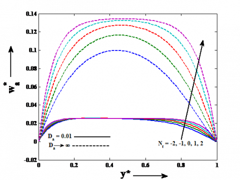
To examine the effects of different flow parameters to the fluid flow problem the graphs for fluid velocity and the shear stress at the moving porous plate are computed and generated for various values of different flow parameters taking $H_{a}^{2}=81, \quad t^{*}=0.5, R^{*}=5$ and $R_{e}=4$.The numerical values of flow parameters corresponding to each Figure are given in the caption of the Figure and inside the Figure. Figures 2 and 3 show the influence of Hall current parameter $B_{e}$ on the fluid velocity in the primary and secondary flow directions respectively. It can be seen from Figure 2 that the fluid velocity in the primary flow direction $u_{a}^{*}$ decreases on increasing Hall current parameter $B_{e}$ in case of both the small permeable regime $\left(D_{a}=0.01\right)$ and pure fluid regime$\left(D_{a} \rightarrow \infty\right)$.Figure 3 exhibits that fluid velocity in the secondary flow direction $w_{a}^{*}$ increases on increasing Hall current parameter $B_{e}$ in case of both the small permeable regime and pure fluid regime. This implies that in case of both the small permeable regime and pure fluid regime, Hall current tends to reduce fluid velocity in the primary flow direction whereas it has reverse effect on the fluid velocity in the secondary flow direction. The usual nature of Hall current is to induce secondary flow in the flow-field, our result comply with it. Figures 4 and 5 illustrate the effect of ion-slip parameter $B_{i}$ on the fluid velocity in the primary and secondary flow directions respectively. Both the fluid velocity in the primary flow direction $u_{a}^{*}$ and fluid velocity in the secondary flow direction $w_{a}^{*}$ decrease on increasing ion-slip parameter $B_{i}$ in case of both the small permeable regime and pure fluid regime. This means that in case of both the small permeable regime and pure fluid regime, ion-slip tends to reduce fluid velocity in both the primary and secondary flow directions. Figure 6 illustrates the effect of permeability parameter $D_{a}$ on the fluid velocity in both the primary and secondary flow directions. Both the fluid velocity in the primary flow direction $u_{a}^{*}$ and fluid velocity in the secondary flow direction $w_{a}^{*}$ increase on increasing the permeability parameter$D_{a}$. This concludes that permeability tends to enhance fluid velocity in both the primary and secondary flow directions. Figures 7 and 8 exhibit the influence of suction/injection parameter $N_{t}$ on the fluid velocity in the primary and secondary flow directions respectively. Both the fluid velocity in the primary flow direction $u_{a}^{*}$ and fluid velocity in the secondary flow direction $w_{a}^{*}$ increase on increasing suction parameter $N_{t}$ and these decrease on increasing injection parameter $N_{t}$ in case of pure fluid regime. The fluid velocity in the primary flow direction $u_{a}^{*}$ decreases on increasing suction parameter $N_{t}$ and it increases on increasing injection parameter $N_{t}$ in the lower half of the channel whereas these effects are reversed in the upper half of the channel in case of small permeable regime. The fluid velocity in the secondary flow direction $w_{a}^{*}$ increases on increasing suction parameter $N_{t}$ and it decreases on increasing injection parameter $N_{t}$ in case of small permeable regime. This implies that in case of pure fluid regime, suction tends to enhance fluid velocity in both the primary and secondary flow directions whereas injection has reverse effect on these. In case of small permeable regime, suction tends to enhance fluid velocity in the primary flow direction in the upper half of the channel and fluid velocity in the secondary flow direction throughout the channel whereas injection has reverse effect on these. In case of small permeable regime the nature of fluid velocity in primary flow direction in the lower half of the channel is reversed due to permeability of the medium.
Figure 2. Fluid velocity distribution in the primary flow direction when $\mathrm{B}_{i}=0.5$ and $N_{t}=1.0$
Figure 3. Fluid velocity distribution in the secondary flow direction when $\mathrm{B}_{i}=0.5$ and $N_{t}=1.0$
Figure 4. Fluid velocity distribution in the primary flow direction when $\mathrm{B}_{e}=0.25$ and $N_{t}=1.0$
Figure 5. Fluid velocity distribution in the secondary flow direction when $\mathrm{B}_{e}=0.25$ and $N_{t}=1.0$
Figure 6. Fluid velocity distribution in the primary and secondary flow directions when $\mathrm{B}_{e}=0.25, \mathrm{B}_{i}=0.5$ andand $N_{t}=1.0$
Figure 7. Fluid velocity distribution in the primary flow direction when $\mathrm{B}_{e}=0.25$ and $\mathrm{B}_{i}=0.5$
Figure 8. Fluid velocity distribution in the secondary flow direction when $\mathrm{B}_{e}=0.25$ and $\mathrm{B}_{i}=0.5$
Figure 9. Shear stress distribution in the primary flow direction when $N_{t}=1.0$
Figure 10. Shear stress distribution in the secondary flow direction when $N_{t}=1.0$
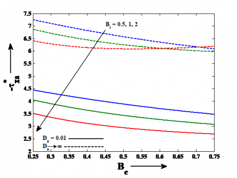
Figure 11. Shear stress distribution in the primary and secondary flow directions when $B_{e}=0.25$ and $B_{i}=0.5$
Figures 9 and 10 display the effects of Hall current parameter $B_{e}$ and ion-slip parameter $B_{i}$ on shear stress at the moving porous plates in the primary flow direction $\tau_{x a}^{*}$ and shear stress at the moving porous plate in the secondary flow direction $\tau_{z a}^{*}$ respectively. Shear stress at the moving porous plate in the primary flow direction $\tau_{x a}^{*}$ decreases on increasing Hall current parameter $B_{e}$ in case of both the small permeable regime and pure fluid regime whereas it decreases on increasing ion-slip parameter $B_{i}$ in case of the small permeable regime and pure fluid regime when $B_{i}=0.5$ and 1.Shear stress at the moving porous plate in the secondary flow direction $\tau_{z a}^{*}$ increases on increasing Hall current parameter $B_{e}$ and it decreases on increasing ion-slip parameter $B_{i}$ in case of both the small permeable regime and pure fluid regime. This implies that in case of both the small permeable regime and pure fluid regime, Hall current tends to reduce shear stress at the moving porous plate in the primary flow direction whereas it has reverse effect on shear stress at the moving porous plate in the secondary flow direction. In case of pure fluid regime, ion-slip tends to reduce shear stress at the moving porous plate in the primary flow direction when $B_{i}=0.5$ and 1 and shear stress at the moving porous plate in secondary flow direction. In case of small permeable regime, ion-slip tends to reduce shear stress at the moving porous plate in both the primary and secondary flow directions. Figure 11 depicts the effects of permeability parameter $D_{a}$ and suction/injection parameter $N_{t}$ on the shear stress at the moving porous plate in the primary flow direction $\tau_{x a}^{*}$ and the shear stress at the moving porous plate in the secondary flow direction$\tau_{z a}^{*}$. Both the shear stress at the moving porous plate in the primary flow direction $\tau_{x a}^{*}$ and the shear stress at the moving porous plate in the secondary flow direction $\tau_{z a}^{*}$ increase on increasing permeability parameter $D_{a}$ and suction parameter $N_{t}$ while it decrease on increasing injection parameter $N_{t}$.This shows that permeability and suction tend to enhance shear stress at the moving porous plate in both the primary and secondary flow directions whereas injection has reverse effect on these.
It is noticed from Figures 2 to 11 that both the fluid velocity and the shear stress at the moving porous plate in case of pure fluid regime is more than the fluid velocity and shear stress at the moving porous plate in case of small permeable regime.
In the present study the effects of Hall current, ion-slip and permeability on unsteady magnetohydrodynamic Couette-Poiseuille flow within porous plates filled with porous medium in the presence of a moving uniform transverse magnetic field is carried out. Two particular cases for the medium filled within the porous plates are considered i.e. (i) the case of small permeable regime and (ii) the case of pure fluid regime. Major findings are summarized below:
In case of both the small permeable regime and pure fluid regime, Hall current tends to reduce fluid velocity in the primary flow direction and shear stress at the moving porous plate in the primary flow direction whereas it has reverse effect on the fluid velocity in the secondary flow direction and shear stress at the moving porous plate in the secondary flow direction. Ion-slip tends to reduce fluid velocity in both the primary and secondary flow directions whereas it tends to reduce shear stress at the moving porous plate in the secondary flow direction. In case of pure fluid regime, suction tends to enhance fluid velocity in both the primary and secondary flow directions whereas injection has reverse effect on these. Ion-slip tends to reduce shear stress at the moving porous plate in the primary flow direction when $B_{i}=0.5$ and 1. In case of small permeable regime, suction tends to enhance fluid velocity in the primary flow direction in the upper half of the channel and fluid velocity in the secondary flow direction throughout the channel whereas injection has reverse effect on these. Ion-slip tends to reduce shear stress at the moving porous plate in the primary flow direction.
Permeability tends to enhance fluid velocity in both the primary and secondary flow directions. Permeability and suction tend to enhance shear stress at the moving porous plate in both the primary and secondary flow directions whereas injection has reverse effect on these.
Authors are thankful to the reviewers for their valuable comments and suggestions. S. Ghousia Begum is thankful to University Grant Commission (ugc), New Delhi for providing financial assistance to carry-out this research work.
$B_{0}$ applied magnetic field (T)
$B_{e}$ Hall current parameter
$B_{i}$ ion-slip parameter
$D_{a}$ permeability parameter
$h$ characteristic length $(m)$
$H_{a}$ Hartmann number
$k$ permeability $\left(m^{2}\right)$
$n$ positive integer
$N_{t}$ suction/injection parameter
$p^{\prime}$ modified pressure (Pa)
$R$ modified pressure gradient
$u$ fluid velocity in $x$-direction $(m / s)$
$U_{0}$ characteristic velocity $(m / s)$
$v$ fluid velocity in $y$-direction $(m / s)$
$w$ fluid velocity in $z$-direction $(m / s)$
Greek symbols
$\sigma$ electrical conductivity $(S / m)$
$\rho$ fluid density $\left(k g / m^{3}\right)$
$v$ coefficient of viscosity $\left(m^{2} / s\right)$
$\mu_{e}$ magnetic permeability
[1] K. R. Cramer and S. I. Pai, Magnetofluid-dynamics for Engineers and Applied Physicists, New York: McGraw-Hill Book Comp., 1973.
[2] H. Sato, “The Hall effect in the viscous flow of ionized gas between parallel plates under transverse magnetic field,” J. Phy. Soc. Japan, vol. 16, no. 7, pp. 1427–1433, 1961. DOI: 10.1143/JPSJ.16.1427.
[3] M. L. Mittal, G. H. Masapathi and B. N. Rao, “Entrance flow in a MHD channel with Hall and ion-slip currents,” AIAA Journal, vol. 14, no.12, pp. 1768-1770, 1976. DOI: 10.2514/3.7285.
[4] V. M. Soundalgekar, N. V. Vighnesam and H. S. Takhar, “Hall and ion-slip effects in the MHD couette flow with heat transfer,” IEEE Trans. Plasma Sci., vol. 7, no. 3, pp. 178-182, 1979. DOI: 10.1109/TPS.1979.4317226.
[5] P. C. Ram, A. K. Singh and H. S. Takhar, “Effects of Hall and ion-slip currents on convective flow in a rotating fluid with a wall temperature oscillation,” Magnetohydrodynamics and Plasma Research, vol. 5, pp. 1-16, 1995.
[6] H. S. Takhar and B. K. Jha, “Effects of Hall and ion-slip currents on MHD flow past an impulsively started plate in a rotating system,” Magnetohydrodynamics and Plasma Research, vol. 8, pp. 61-72, 1998.
[7] H. A. Attia. (2005). Unsteady couette flow with heat transfer considering ion-slip. Turk. J. Phys. [Online]. vol. 29, pp. 379-388. Available: http://journals.tubitak.gov.tr/physics/issues/fiz-05-29-6/fiz-29-6-7-0509-8.pdf
[8] H. Naroua, H. S. Takhar, P. C. Ram, T. A. Beg, O. A. Beg and R. Bhargava, “Transient rotating hydromagnetic partially-ionized heat-generating gas dynamic flow with Hall/ionslip current effects: finite element analysis,” Int. J. Fluid Mech. Res., vol. 34, no. 6, pp. 493-505, 2007. DOI: 10.1615/InterJFluidMechRes.v34.i6.10.
[9] O. A. Beg, J. Zueco and H. S. Takhar, “Unsteady magnetohydrodynamic Hartmann-Couette flow and heat transfer in a Darcian channel with Hall current, ion-slip, viscous and joule heating effects: Network numerical solutions,” Commun. Nonlinear Sci. Numer. Simulat., vol. 14, pp. 1082-1097, 2009. DOI: 10.1016/j.cnsns.2008.03.015.
[10] B. K. Jha and C. A. Apere, “Combined effect of Hall and ion-slip currents on unsteady MHD Couette flows in a rotating system,” J. Phys. Soc. Japan, vol. 79, no. 10, 104401 (9 pages), 2010. DOI: 10.1143/JPSJ.79.104401.
[11] B. K. Jha and C. A. Apere, “Time-dependent MHD Couette flow of rotating fluid with Hall and ion-slip currents,” Appl. Math. Mech., vol. 33, no. 4, pp. 399-410, 2012. DOI: 10.1007/s10483-012-1559-9.
[12] J. K. Singh, S. G. Begum and N. Joshi. (2006). Effects of Hall current and ion-slip on unsteady hydromagnetic generalized Couette flow in a rotating darcian channel. J. Math. Model. [Online]. vol. 3, no. 2, pp. 145-167. Available: http://jmm.guilan.ac.ir/article_1249_0.html
[13] D. B. Ingham and I. Pop, “Transport phenomena in porous Media II,” in Pergamon, Oxford, 2002.
[14] A. J. Chamka, “Flow of two-immiscible fluids in porous and non-porous channels,” ASME J. Fluids Eng., vol. 122, no. 1, pp. 117-124, 2000. DOI: 10.1115/1.483233.
[15] A. J. Chamka, “unsteady laminar hydromagnetic flow and heat transfer in porous channels with temperature-dependent properties,” Int. J. Numerical Methods for Heat & Fluid Flow, vol. 11, no. 5, pp. 430-448, 2001. DOI: 10.1108/EUM0000000005529.
[16] O. D. Makinde and P. Y. Mhone. (2005). Heat transfer to MHD oscillatory flow in a channel filled with porous medium. Rom. J. Phys. [Online]. vol. 50, pp. 931-938. Available: http://www.ifin.ro/rjp/2005_50_9-10/0931_0938.pdf
[17] O. A. Beg, L. Sim, J. Zueco and R. Bhargava, “Numerical study of magnetohydrodynamic viscous plasma flow in rotating porous media with Hall currents and inclined magnetic field influence,” Commun. Nonlinear Sci. Numer. Simulat., vol. 15, no. 2, pp. 345-359, 2010. DOI: 10.1016/j.cnsns.2009.04.008.
[18] C. Israel-Cookey, E. Amos, and C. Nwaigwe, “MHD oscillatory Couette flow of a radiating viscous fluid in a porous medium with periodic wall temperature,” Am. J. Sci. Ind. Res., vol. 1, no. 2, pp. 326-331, 2010. DOI: 10.5251/ajsir.2010.1.2.326.331.
[19] D. S. Chauhan and R. Agrawal, “Effects of Hall current on MHD Couette flow in a channel partially filled with porous medium in a rotating system,” Meccanica, vol. 47, no. 2, pp. 405-421, 2012. DOI: 10.1007/s11012-011-9446-9.
[20] K. D. Singh and A. Mathew. (2012). An oscillatory free convective flow through porous medium in a rotating vertical porous channel. Global J. Sci. Front. Res. [Online]. vol. 12, no. 3, pp. 51-64. Available: http://www.journalofscience.org/index.php/GJSFR/article/view/607
[21] K. D. Singh and R. Pathak. (2012). Effect of rotation and Hall current on mixed convection MHD flow through a porous medium filled in a vertical channel in presence of thermal radiation. Indian J. Pure & Appl. Phys. [Online]. vol. 50, no. 2, pp. 77-85. Available: http://14.139.47.15/handle/123456789/13462
[22] K. D. Singh, B. P. Garg and A. K. Bansal. (2014). Hall current effect on Visco-elastic MHD oscillatory convective flow through a porous medium in a vertical channel with heat radiation. Proc. Indian Natn. Sci. Acad. [Online]. vol. 80, no. 2, pp. 333-343. Available: http://www.insa.nic.in/writereaddata/UpLoadedFiles/PINSA/Vol80_2014_2_Art17.pdf
[23] S. Ahmed and A. J. Chamkha, “Hartmann Newtonian radiating MHD flow for a rotating vertical porous channel immersed in a Darcian porous regime: An exact solution,” Int. J. Num. Methods Heat Fluid Flow, vol. 24, no. 7, pp. 1454-1470, 2014. DOI: 10.1108/HFF-04-2013-0113.
[24] G. S. Seth, P. K. Mandal and R. Sharma. (2015). Hydromagnetic Couette flow of Class-II and heat transfer through a porous medium in a rotating system with Hall effects, J. Math. Model., [Online]. vol. 3, no. 1, pp. 48-75. Available: http://jmm.guilan.ac.ir/pdf_205_5810e3b245e5f7d2eacd809a10c2149a.html
[25] G. W. Sutton and A. Sherman, “Engineering magnetohydrodynamics,” New York: McGraw-Hill Book Comp., 1965.
[26] N. W. McLachlan, “Complex variable and operational calculus with technical applications,” New York: Cambridge University Press, 1947.