OPEN ACCESS
Natural convective heat transfer between two zones through an opening is studied experimentally. Experiments were carried out in a full scale calorimetric chamber (5.5m x 2.5m x 2.5m) inside which two zones are connected by an opening of height 2.05 m and varying width. Temperature differences were maintained by two active vertical walls located on either side of the doorway. Convective heat transfers were deduced from the energy balances and expressed interns of Nusselt, Grashof and Prandtl numbers, i.e.: $\frac{N u}{P r}=C G r^{M}$, where $\mathrm{C}=3 \mathrm{C}_{d}$. Experiments were performed at power injection levels from 95 W to 1250W for Grashof number in the range 8x10⁸≤ Gr ≤ 4x10¹⁰. Empirical correlation lows between Nusselt, Prandtl and Grashof were obtained for various temperature differences between the hot and cold zones. Also, other criteria relations were developed in terms of varying aspect ratio ADS. The results obtained show that the C and M parameters depend upon the way temperature differences are chosen for determining the Grashof number. These coefficients lay on average: 1.0 ≤ C≤ 1.9 corresponding to a discharge coefficient 0.35≤Cd≤ 0.63 and 0.390≤M≤0.422. When wall temperatures are considered M = 0.27.
Convective heat through an opening, Convection in partitioned enclosure, Calorimetric chamber.
Natural convection in enclosures caused by a difference in air density affects the general movements of air in a building and must be evaluated for accurate thermal zones heat and mass balance. For design purposes it is necessary to know the magnitude of the natural convection through a doorway as a function of the temperature difference between two zones. This subject has been studied extensively in the past few years experimentally as well as by numerical models. In both approaches simplifications were however assumed.
Usually, the process is described in terms of the Nusselt Grashof and Prandtl numbers, in relation:
$\frac{N u}{P r}=C G r^{0.5}$
Where the exponent 0.5 derives from theoretical development based on a simplified flow model through the opening (laminar, one dimensional flow of ideal fluid). Experimental studies had been carried out usually in a room, with a partition where two walls were the active, isothermal, hot and cold surfaces and the others (passive) were assumed, to be adiabatic. Brown and Solvason [1], in experiments with a vertical partition, obtained C coefficients between 0.2 and 0.33 for ideal laminar flow. Baraka’s review [2] reported that the C coefficient is a function of the magnitude of the temperature difference. He indicated that the most accurate
correlation was the mean temperature of the air flowing out of the warm room and that flowing into the warm room measured on a grid at the opening. Eckert and Carlson [3] defined a criterial relation using the hot and cold wall temperature difference to define the Grashof number. In this case, the exponent equals 0.24. A few investigations are carried out based on similitude model experiments [4], [5], [2]. In those cases, the flow conditions in the scale models and real world may not be equivalent even for similar Grashof numbers. This is especially true if other fluids than air were used, without full hydrodynamic similarity. Numerical models were also based on many simplifications. Zimmerman and Acharya [6] assume perfectly conducting active walls; the flow is laminar and two dimensional; heat transfer by radiation is not included. Newell and Schmidt [7] carried out numerical simulations on an enclosure with isothermal active walls, assuming the laminar flow of ideal fluid. The effect of radiation is here again neglected. Ansari [8] investigated numerically natural convection in a rectangular enclosure where flow is induced due to the constant partial heating at lower half of the left vertical wall and partial cooling at upper half of the right vertical wall, the rest walls being adiabatic. The simulation shows that increasing Rayleigh number Ra implies the enhancement of the thermal buoyancy force, which in turn increases the thermal convection in the cavity it is also found that the heat transfer rate attains its maximum value at aspect ratio A=1.0.
Ehsan Rezaci & Al. [9] used an adaptive neuro –fuzzy inference system (ANFIS) to predict the free convection in a partitioned cavity consisting of an adiabatic partition. The training data for optimizing the ANFIS structure is obtained experimentally. They found for the best ANFIS structure obtained in this study, the mean relative errors of the train and test data were found to be 0.055% and 1.735% respectively, which shows that ANFIS can predict the experimental results precisely. In their work Singh AK and Roy S [10] visualized heat flow during natural convection within a tilted square cavity inclined using Bejan’s eatlines approach. The enclosure is bounded by a hot wall (case 1: isothermal heating and case 2:non-isothermal heating), isothermally cooled walls and in the presence of adiabatic wall.The results are presented in terms of streamlines, isotherms, heatlines and local and average Nusselt numbers. More recently Kalidasan. K and Velkennedy. R [11], presented a computational study of steady laminar natural convection inside the square enclosure with cold partition wall centrally placed on top and bottom.The height of the opening in the partition walls were 10%, 20%, and 30% of height of enclosure. The cross flow between the vertical walls through the opening in the central partition wall was considered for varying height of openings for Ra= $10^{3}, 10^{4},$ and $10^{5}$ . Due to the dominance of buoyancy forces, heat transfer rate increases when Rayleigh number increases for all the cases, Sanvicente. E, Giroux-Julien.S [12] presented an experimental study on natural convection flows in a differentially heated open channel configuration. In this investigation the thermal configuration considers one wall heated uniformly while the other is not heated.The experimental evidence shows that the flow is neither really turbulent nor purely laminar for the range of Rayleigh numbers considered.
A quantitative model is developed by Dong Yang and Al [13] for convection of a shaft. The model can predict the vertical distributions of temperature and pressure, mass inflow rate, neutral plane location, and is extended to determine the conditions for transition from unidirectional to bi-directional convection. In order to identify the optimum location of the active wall for better heat transfer, in consideration with entropy generation Mahapatra PS [14] investigated natural convection in a partially heated enclosure, considering six different configurations with enclosure aspect ratios 1.5, 2, and 4. From the numerically simulated results, different sets of active wall locations have been identified for better heat transfer, thermal mixing and temperature uniformity for Rayleigh number $10^{3}-10^{6}$ and Prandtl number 0.71.
Authors did not always determine convective interzone couplings by means of a relationship between Nu and Gr.Therefore, the review of previous works yields comparison results only when the same criterial relation is used; however there remains a problem of definition of the temperature difference between warm and cold zones. Many authors just consider a uniform temperature in every zone. This assumption is different from the real situation where there exists a temperature gradient (vertical and horizontal) in every zone.
The purposes of our work in continuing preliminary analyses [15] are:
1) Finding with the best possible accuracy the empirical criterial relation for natural convective heat transfert between zones, through:
- Comparable average temperature in the test chamber for all experiments;
- Greater temperature differences between the zones for widening the scope of the criterial relation.
2) Investigate of the influence of the door’s width (varying door aspect ratio $A_{D S}$ ).The experiment is divided into 4 series for widths varying from 0.685m to 1.26m.
3) Appreciate the influence of the definition of temperature differences on the parameters of the criterial relation.
Experiments were carried out in a full scale test chamber with two zones connected to each other by a large opening of the size of a realistic residential doorway. The working fluid used here is air. Grashof numbers vary in the range 8x 10⁸ ≤Gr≤4x 10¹⁰ . Temperature differences between the two zones range: for active walls: 6° C to 36°C, for the air: 0.6°C to 6°C.In order to maintain the air mean temperature of the overall chamber reasonably constant at different power injection levels ( 95 W to 1250W ) the heating and cooling systems were regulated. As a result this temperature varied by ± 5 k.
Definitions of temperature differences:
∆ $T_{\text {wall}}$ temperature difference between hot and cold walls.
∆ $T_{\text {mean }-\text { door }}$ : temperature difference at the plane of opening between average temperatures above and under the midpoint of the door.
∆ $T_{u p-d o w n}$ : difference between temperature taken on top of columns A, B, C and bottom of D, E, F.
∆ $T_{\max -\min }$ : difference at the door plane between highest recorded temperature above the axis of the door and lowest temperature under the axis.
∆ $T_{\text {centr.col}}$ : temperature difference between average temperatures on central columns of cold and hot zones.
∆ $T_{\text {weight}}$ : temperature difference at the plane of opening between velocities weighted average temperature above and uneder axis of the door.
∆ $T_{m}$ : difference between average temperatures taken on columns A, B, C and D, E, F respectively.
∆ $T_{C-F}$ : difference between temperatures taken on columns C and F.
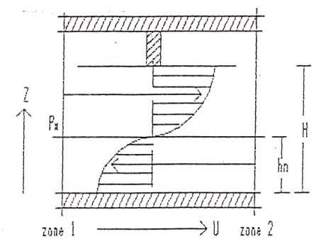
Let us have two large sealed cavities, separated from one another by a vertical partition with a rectangular opening of height H and width W. (Fig.1)
Figure 1. Conceptual pattern of 1-D inter-zone air flow
Based on Bernoulli equation and mass continuity equation, we have [16]:
$W C_{d} \int_{0}^{H} v(z) d_{z=0}$
Where $C_{d}$ a discharge coefficient and v (z) is the air velocity at height z.
$\mathrm{V}(\mathrm{z})=C_{d}\left(2 g \frac{\Delta \rho}{\rho}\left|z-h_{n}\right|\right)^{0.5}$
Where $h_{n}$ represents the height of neutral plane. Assuming $h_{n}$ = H/2 we can find for the volume flow rate:
$V_{1-2}=C_{d} W \int_{h_{n}}^{H} v(z) d z h_{n} \leq z \leq H$
$V_{1-2}=1 / 3 C_{d}(g \beta \Delta T H)^{0.5}$ (1)
Where: $\beta=\frac{1}{\bar{T}}, \bar{T}=\frac{1}{2}\left(T_{1}+T_{2}\right)$
Heat transport by the air flow between the two zones becomes:
$Q_{c}=\rho C_{P} \Delta T V_{1-2}=h_{c} \Delta T W$ (2)
$h_{c=1} / 3 C_{d} \rho C_{P}(g \beta \Delta T H)^{0.5}$ (3)
Reorganizing this equation to introduce Nusselt, Prandtl and Grashof numbers, we obtain:
$\frac{N u}{P r}=C G r^{M}$ (4)
The C coefficient and M exponent will be determined by experimental studies.
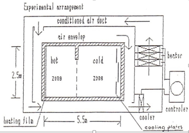
Experiments were carried out in the calorimetric chamber shown in fig.2.The calorimetric chamber (5.5mx 2,5m) is made of 102 mm polystyrene foam clad by 1mm aluminum sheets on either sides. Two zones in the chamber are communicating through an opening of height 2.05 m and varying width (1.26m, 0.98m, 0.685m). The partition is made of the same material as the enclosure. The calorimetric chamber is isolated from the environment by an extra enclosure creating an air envelope in between. The air temperature in the envelope space is controlled by an air handling unit installed next to the test chamber and connected by supply and return ducts. The end wall in the hot zone was heated by a uniformly distributed resistance film as heat source. The opposite wall in the cold zone was supplied with cooling plates with flowing cold water for evacuating heat from the chamber. Such a heat extraction device enabled large temperature differences between the zones, than in the previous preliminary experiments.
Figure 2. The test chamber and its arrangements
A total of 130 thermocouples (copper-constantan, shielded to reduce radiation error) are used for the measurement of surface and air temperatures. A movable trolley was used to carry sensors for measurements of air temperature and velocity in the plane of opening. Measurements include:
1- External and internal surface temperatures of each wall.
2- Air temperatures in the envelope space are measured by 13 thermocouples.
3- Air temperatures in each zone are measured by three vertical columns situated at relevant positions with 11 thermocouples on each column (see Figure 3).
Figure 3. Calorimetre chamber and positions of column holding thermocouples
4- In the plane of the opening, temperature and air velocity are measured. Measurements of instantaneous air velocity and temperature were done at rate of five samples per second over a period of twenty seconds in each position.
Experiments were carried out for various power levels from 95 w up to 1250 w. This yielded Grashof numbers in the range of 8 x 10⁸ < Gr < 4 x 10¹⁰ or net convective heat transfers where $65 \mathrm{W}<\dot{Q}_{\text {conv}}<930 \mathrm{W}$ .
For each door width, series of power injections were repeated. The door width was 0.685m, 0.98m and 1.26m for the test series II, III and IV respectively. As a whole 32 situations were investigated. Convective heat exchanges through the doorway ( $\dot{Q}_{c o n v}$ ) have been deduced from the heat balance expressed on the hot zone. Good results are obtained when comparing heat balance from hot and cold zone (error $\approx$ 5%).The height H of the opening is used as characteristic length to calculate the dimensionless Grashof and Nusselt numbers as follows:
$N u_{H}=\frac{Q c}{W \Delta T K} ; G r_{H}=\frac{g \beta \Delta T H^{3}}{v^{2}}$
Obviously the use of each temperature difference leads to different Nu, Pr and Gr numbers. Nevertheless there remains the problem of selecting the right definition in order to calculate the volume and mass flow rate through the doorway.
The air flow rate through the doorway can be deduced from velocity measurements. It could possibly be indicated which definition of temperature difference would yield the best correspondence. The parameters of criterial relation Nu/Pr =C $G r^{M}$ were determined for all tests. Figures 4, 5 show examples of relations Nu / Pr vs Gr. Then these criterial relations were arranged in groups under the same temperature differences in order to observe how C and M parameters vary with the door width. From experiments the empirical coefficient C was found to be equal to 3 $C_{d}$ . Table 1 shows some empirical relations obtained during the experiments.
Figure 4. Gr vs Nu/Pr at wall temperature differences
Figure 5. Gr vs Nu/Pr at central columns temperature differences
Table 1. Experimental criterial relations Nu/Pr=f(Gr) for the various definitions of temperature difference
|
Door’s width (m) |
1.26 |
0.98 |
|
Nu/Pr Walls $T_{w a l l}$ Est. Error |
500 – 1100 1.4 $G r^{0.2665}$ 10 |
900 – 1300 1.643 $G r^{0.371}$ 2x 101 |
|
Nu/Pr Column $T_{\text {centr}-c o l}$ Est.Error |
5000 – 12000 1.685 $G r^{0.3975}$ 1.4x 10² |
6000 – 12000 1.026 $G r^{0.4199}$ 4.5x 10² |
|
Nu/Pr $T_{\text {door mean}}$ Est.Error |
6500 – 13000 6.08 $G r^{0.344}$ 8.7x 10² |
10000 – 14000 2.45 $G r^{0.39}$ 3.5x 10² |
|
Nu /Pr $T_{\text {door weight}}$ Est.Error |
4000 – 10000 1.77 $G r^{0.187}$ 6.9 x 10² |
8000 – 11000 2.225 $G r^{0.179}$ 4.2 x 10² |
Good accuracy of approximation was obtained for most temperature differences which have been considered, notably:
. $\Delta T_{\text {wall}}$ (error $\approx$ 2%)
. $\Delta T_{\text {centr.col}}$ (er.1.18%-1.65%)
. $\Delta T_{\text {mean.door}}$ (er.8.9%-10%)
The remaining temperature differences gave unsatisfactory results. The values of M found are almost the same M $\approx$ O,40 for all cases except the $\Delta T_{\text {wall}}$ case where M = 0.27 which is the classical coefficient for convective heat transfer to and from vertical walls [17[ .In order to define the influence of the width upon C, M is fixed at each definition of temperature difference a relation of the following form is deduced from data: $\frac{N u}{P r}=\left(A+B \frac{W}{H}\right) G r^{M}$ Where A and B are constants for each temperature differences. A complete set of relations C = f (W/H) for all temperature differences is stated in table 2.
Table 2. Emperical correlations of Nu/Pr=f(Gr) for various aspsct ratio $A_{D S}$ =W/H
|
Temperature differences |
Criterial relations for various $\Delta T$ |
|
$T_{W a l l}$ $T_{\text {col.centr}}$ $T_{c o l-C F}$ $T_{c o l-B E}$ $T_{u p-d o w n \text { Par}}$ $T_{u p-d o w n \text { Per}}$ $T_{\text {door mean}}$ $T_{\text {door weight }}$ T_{\text {door maxmin}} |
(3.99 – 4.465 W/H) $G r^{0.27}$ (1.83 – 1.01 W/H) $G r^{0.41}$ (5.17 _ 2.467 W/H ) $G r^{0.39}$ (2.72 _ 3.08 W/H) $G r^{0.41}$ (5.83 _ 3.84 W/H) $G r^{0.33}$ (6.48 _ 4.78 W/H) $G r^{0.33}$ (2.54 _ 0.32 W/H) $G r^{0.39}$ (2.419 _ 1.26 W/H) $G r^{0.39}$ (1.666 _ 0.728 W/H) $G r^{0.39}$ |
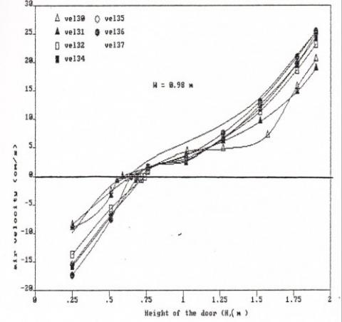
The air velocity is measured in the doorway. These velocity values are used to calculate mean weighted air temperature in the plane of opening as well as for finding the mean values of velocity. Then the velocity profile on the plane of opening is plotted, (e.g. fig 6 and 7). The neutral plane is indicated by zero values of velocities. This neutral axis varied from an approximate height of H /4to just under H / 3.This variation depends upon the door width, in such a way that the neutral axis goes up as the door way decreases. In no case, the neutral axis was found to lay in the mid-height of the opening as assumed in the theoretical analysis.
Figure 6. Profile of the air velocity in the door’s plane (W=0,98m)
Figure 7. Profile of the air velocity in the door’s plane (W=1,26m)
The heat transfer balances for the hot and cold zones and for the whole test chamber gave consistent results to within $\approx 4 \%$ accuracy. Based on investigation results at different width of the doorway, empirical equations have been found for the convective heat transfer between zones. As result the C and M parameters in the criteria relations for various definitions of temperature difference, settle around:
$1.0<C<1.9$ correspnding to $0.35 \leq C_{d} \leq 0.63$
$0.39<M<0.42$
These results are in good agreement with those obtained by other authors experimentally [1],[15] as well as those obtained numerically [8] and [14].
The influence of the opening's width over the convective heat transfer, clearly appears. A correlation C = f (aspect ratio W/H) is stated in table 2.
Being in good agreement with the general literature, it still remains that the present results are specific to the particular geometry and the supply heating and cooling conditions of the test chamber. However it is interesting to note that estimations of convective heat transfer between rooms through normal doors in residential buildings can be calculated using empirical correlation proposed in this paper as the experiments were performed in a realistic full scale test chamber.
The author wish to thank Professor Jean LEBRUN of Liège University for his help and precious advice that accompanied us throughout this research.
|
$A_{D S}$ |
door Aspect ratio W/H |
|
C |
coefficient |
|
$C_{d}$ |
discharge coefficient |
|
$C_{P}$ |
specific heat of air ( J/Kg K ) |
|
g |
gravitational acceleration ( m / $S^{2}$ ) |
|
$G_{r}$ |
grashof number |
|
H |
height of opening ( m ) |
|
$h_{c}$ |
convective coefficient ( W / $m^{2}$ K ) |
|
$h_{n}$ |
height of neutral axis |
|
T |
temperature (K) |
|
$T_{1,2}$ |
temp.of hot and cold zone (K) |
|
$\dot{Q}$ |
heat flow rate ( W) |
|
K |
thermal conductivity ( W / m K ) |
|
M |
exponent |
|
$N_{u}$ |
Nusselt number |
|
Pr |
Prandtl number |
|
v |
air velocity ( m / s ) |
|
V |
volume flow rate ( $m^{3}$ / s) |
|
Greek symbols |
|
|
ν |
Kinematic viscosity of air ( $m^{2}$ / s ) |
|
$\beta$ |
coefficient of thermal expansion of air ( 1 / K ) |
|
$\rho$ |
density of air ( Kg / $m^{3}$ ) |
|
$\Delta T$ |
temperature difference (K) |
1. Brown W.C. and Solvason K.R., “Natural convection through rectangular opening in Partition 1, Vertical position,” Int. J. Heat Mass Transfer, vol 5, 1962.
2. Brakat S.A., “Inter-zone convective heat transfer in buildings: A revue,” Int. Climat Architecture Congress, 1-3 July, 1986, Louvain-La-Neuve.
3. Eckert E.R.G. and Carlson O.W., “Natural convection in air layer enclosed between two vertical plates with different temperatures,” Int. J. Heat Mass Transfer, vol 2, 1961.
4. Nansteel M.W. and Greif R., “Natural convection in undivided and partially divided rectangular ennclosures,” J. of Heat Transfer, vol. 103, 198.
5. Nansteel M.W. and Greif R., “An investigation of natural convection in enlosures with two- and three-dimensional partitions,” Int. J. Heat Mass Transfer, vol.27, 1984.
6. E. Zimmerman, S. Acharya, “Free convection heat transfer in a partially divided vertical enclosure with conducting end walls,” Int. J. Heat and Mass Transfer, 30 (1987), pp. 319–331.
7. Newell M.E. and Schmidt F.W., “heat transfer by laminar natural convection within rectangular enclosures,” J. of Heat Transfer, Feb. 1970.
8. Ansari S.R., “Numerical investigation of natural convection in a rectangular enclosure due to partial heating and cooling at vertical walls,” Communications in Nonlinear Science and Numerical Simulation, volume 17, June 2012.
9. Ehsan Rezaci, Alimohammed Karami, “Modeling the free convection heat transfer in a partitioned using ANFIS,” International Communications in Heat and Mass Transfer, volume 39, March 2012.
10. Abhishek Kumar Singh, S. Roy, “Visualization of heat transport during natural convection in a tilted square cavity: Effect of isothermal and nonisothermal heating,” Numerical Heat Transfer, Part A: Applications: An International Journal of Computation and Methodology, Volume 61 Issue 6, 2012.
11. K. Kalidasan, R. Velkennedy, “Numerical investigation on natural convection inside the ventilated square enclosure with vertical mid-partition,” Numerical Heat Transfer, Part A: Applications: An International Journal of Computation and Methodology, Volume 66 Issue 12, 2014.
12. E. Sanvicente, S. Giroux–Julien, “Transitional natural convection flow and heat transfer in an open channel,” International Journal of Thermal Sciences, Volume 63, January 2013.
13. Dong Yang, Tao Du, “A model for analysis of convection induced by stack effect in a shaft with warm airflow expelled from adjacent space,” Energy Buildings, Volume 62, July 2013.
14. Pallab Sinha Mahapatra, Nimal K., “Effect of active wall location in a partially heated enclosure,” International Communication in Heat and Mass Transfer, Volume 61, February 2015.
15. Sebbar Y.Y. and Rebberechts B. and Tang D., “Inter-zone convection heat transfer and air flow patterns,” Report of Laboratory of Thermodynamics, Univ. of Liege, February 1989.
16. E. Zimmerman, S. Acharya, “Free convection heat transfer in a partially divided vertical enclosure with conducting end walls,” Int. J. Heat and Mass Transfer, 30 (1987).
17. Sandberg M., Flow through Large Internal Openings, IEA-ECB Annex XX.
18. M.C. Adams W. H., Heat Transmission, 3rd Edition Mc Graw-Hlll, New York, 1959.