Yanchao Ding* | Zhongfu Xiang | Yayong Li | Xuesong Zhang | Yin Zhou
© 2020 IIETA. This article is published by IIETA and is licensed under the CC BY 4.0 license (http://creativecommons.org/licenses/by/4.0/).
OPEN ACCESS
Long-span deck-type beam-arch composite rigid frame (BACRF) bridge fully integrates the merits of arch bridges and beam bridges, and overcomes the cracking and deflection problems of continuous rigid frame bridges. As a perfect combination of beam bridges and arch bridges, the long-span deck-type BACRF bridge boasts a light structure, a strong bearing capacity, and a powerful spanning capability. From the perspective of mechanical system evolution, this paper theoretically analyzes the structural mechanics of the beam-arch composite system, establishes a half-bridge model for BACRF bridge, and derives the expressions of the internal force and displacement of the beam-arch composite system. Next, finite-element analysis was conducted to analyze how the variation of a single parameter, e.g., rise-span ratio, open web ratio, and side-to-middle span ratio, affects midspan displacement, arch-beam junction displacement, main beam bending moment, and main arch axial force. Finally, the calculation formula for deflection-span ratio of BACRF bridge was proposed based on the maximum hyperplane method. The research results provide a reference for the structural design of similar bridges.
beam-arch composite rigid frame (BACRF) bridge, mechanical system evolution, rise-span ratio, torsion-span ratio, reasonable structure
Beam-arch composite system is a novel structural system, which fully integrates the merits of arch and beam in stress bearing [1]. Compared with T-shaped rigid frames or continuous beams, this system has very small negative bending moment of the fulcrum, positive bending moment in midspan, and the displacement of midspan [2]. It is very suitable for long-span bridge structures, owing to its excellence in mechanical properties, economy, construction convenience, and driving comfort [3].
In the beam-arch composite rigid frame (BACRF) bridge, the negative bending moment of the middle fulcrum can be greatly reduced by hollowing out the web near that fulcrum. The negative bending moment of the main beam peaks at the arch-beam junction, i.e., the corner junction, serving as the key force-bearing part of the bridge structure. This junction plays a controlling role in the structural design.
Li [4] gave a reasonable interval of rise-span ratio for deck-, half-through-, and through-type bridges, and examined the influence of the rise-span ratio over the overall force and deformation of the beam-arch combination bridge. Jin [5] summarized the mechanics and structure problems in the design and construction of beam-arch composite bridge. Bransch [6] compared the strengths and defects of steel arch ribs and concrete arch ribs for beam-arch composite bridge, and proposed a composite section arch rib with a concrete-wrapped rolled steel section; calculation results show that the composite section arch rib satisfies the requirements on bearing capacity at a low cost in the general span range; the proposed arch rib is also easy to construct, because the rolled steel beam can serve as a template, and the steel structure is very light in the erection stage.
Gou [7, 8] created the concept of nominal rigidity for long-span V-shaped rigid frame composite arch bridge, analyzed the influence of structural parameters on the nominal rigidity, and deduced the theoretical equation for the nominal rigidity. In addition, Gou H.Y. discussed the selection of arch-beam rigidity ratio, evaluated the impact of the ratio on internal force distribution, determined the boundary value between rigid arch flexible beam and flexible arch rigid beam, and summed up the nominal rigidity and arch-beam rigidity ratio of existing bridges. Rovira and Tomàs [9] introduced the Nelson Mandela Bridge, composite rigid frame arch bridge with a main span of 150m, in Barcelona, and described the design, construction, and construction control of arches and piers, providing a reference for the design of similar bridges.
Taking a continuous rigid frame bridge with V-shaped piers for example, Xiao [10] investigated the structural stress state of the superstructure of such bridges (i.e., the V-shaped rigid frame arch composite structure) during construction, and identified the weak links under structural stress and the structural deformation state, providing a reference for the stress control and alignment control in bridge construction. Zong et al. [11] presented the design concept of deck-type beam-arch composite bridge, and explored the structural design and calculation of this type of bridge. Yang et al. [12]. Lu [13], Lu et al. [14] conducted a series of research into the design parameters of key sections, as well as static and dynamic mechanism features of composite bridges. Han and Huang [15], Huang and Peng [16] studied the construction method for the hollow area in deck-type beam-arch composite bridge, and applied the method on real bridges. Peng [17] designed a 1:5 reduced scale model of the test beam, carried out static load tests on the mechanical properties of corner junctions on beam-arch composite bridge, and compared the test results with results of the finite-element model for the test beam.
To sum up, the existing studies mainly deal with the structural design and construction methods for small-span deck-type beam-arch composite system, but largely ignore the force mechanism of deck-type beam-arch composite bridge with a main span greater than 120m. To make up for the gap, this paper explores the reasonable structure of long-span deck-type beam-arch composite bridge, and investigates the evolution of the beam-arch composite system. The research results provide a guarantee for the reasonable design of long-span deck-type BACRF bridge.
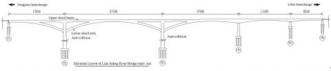
The superstructure of Lijia Jialing River Bridge [18] adopts the beam-arch composite system. The main bridge is 785m long. From left to right, the span lengths are 140, 245, 190, 130, and 80m in turn. Most of the bridge plane belongs to the straight section, while the side of piles with small numbers partly falls on the transition curve. The longitudinal section of the main bridge is arranged on a slope of 0.5% in one direction. There are two-way eight lanes on the bridge. To meet the needs of maintenance and pedestrians, a 2.0m-wide maintenance road, which also serves as sidewalk, is set up on each side of the bridge.
In the superstructure, the bridge deck is 17.85m in width, and the beam bottom is 9.0m in width. The lower chord is a box beam with uniform section, in which the beam is 9.0m wide and 4.8m tall, the web is 0.8m thick, and the top and bottom plates are 0.8m thick. The upper chord is a box beam with variable section, in which the two side cantilevers are 4.4m and 4.45m in length, respectively; the end of each cantilever is 0.85m thick; the top plate is 0.32m thick; the web is 0.8m thick; the beam height is 5.0m in standard section; the bottom plate is 0.28m thick.
The bottom edge of the main beam and lower chord beam changes in the shape of a quadratic parabola. The main beam is made of C60 concrete. The pre-stressed steel strands are 1,860MPaΦs15.2 seven-strand type with standard strength and low relaxation (level II). The vertical view of Lijia Jialing River Bridge is given in Figure 1.
Figure 1. The vertical view of Lijia Jialing River Bridge
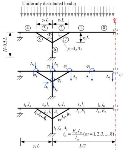
The structural mechanics of beam-arch composite system was derived through theoretical analysis on Mathematica. First, a half-bridge structure model was established for the BACRF bridge (Figure 2), where L is the length of midspan, H is the pier height (which is assumed to be 0.5L), γ1 is the side-to-middle span ratio, γ2 is the proportion of rigid frame section in the main beam, γ3 is the rise-span ratio, and γ4 is the bending rigidity ratio between the rods on upper and lower chords.
The half-bridge model mainly considers the structural response to uniformly distributed load q, and takes account of the different properties of the beam sections in the main span. The entire structure consists of 9 beam elements. The middle of the main span is denoted as pole 0, and the rods on the lower chord as poles 7 and 8. Assuming that the stressed structure is in an elastic state, the displacement method was employed to analyze the structural force. Then, the following equation can be established:
$[K] \cdot[\Delta]=[F]$ (1)
where, [K] is the rigidity matrix (the radius of gyration im of a beam element is related to the elastic modulus Em, section moment of inertia Im, and length lm of the beam; axial rigidity was considered for poles 5-8, but not for poles 0-4); [Δ] is the 12 degrees of freedom (DOFs): Δ0, Δ1, Δ2, Δ3, and Δ4 are the vertical displacement at midspan, variable section of the main beam, junction between open and solid webs, pier top fulcrum, and junction between open web and side-span solid web, respectively; $\varphi_{1}$, $\varphi_{2}$, $\varphi_{3}$, and $\varphi_{4}$ are the corners at the corresponding places, respectively; Δ5, Δ6, and $\varphi_{5}$ are the horizontal displacement, vertical displacement, and angle at the junction between the lower chord and pier, respectively; [F] is the bending moment or shear force induced by external force.
Figure 2. The force model of the structure
By the displacement method, Eq. (1) can be expanded in to a matrix:
$\left(\begin{array}{l}r_{11}, r_{12}, r_{13}, r_{14}, r_{15}, r_{16}, r_{17}, r_{18}, r_{19}, r_{1 A}, r_{1 B}, r_{1 C} \\ r_{21}, r_{22}, r_{23}, r_{24}, r_{25}, r_{26}, r_{27}, r_{28}, r_{29}, r_{2 A}, r_{2 B}, r_{2 C} \\ r_{31}, r_{32}, r_{33}, r_{34}, r_{35}, r_{36}, r_{37}, r_{38}, r_{39}, r_{3 A}, r_{3 B}, r_{3 C} \\ r_{41}, r_{42}, r_{43}, r_{44}, r_{45}, r_{46}, r_{47}, r_{48}, r_{49}, r_{4 A}, r_{4 B}, r_{4 C} \\ r_{51}, r_{52}, r_{53}, r_{54}, r_{55}, r_{56}, r_{57}, r_{58}, r_{59}, r_{5 A}, r_{5 B}, r_{5 C} \\ r_{61}, r_{62}, r_{63}, r_{64}, r_{65}, r_{66}, r_{67}, r_{68}, r_{69}, r_{6 A}, r_{6 B}, r_{6 C} \\ r_{71}, r_{72}, r_{73}, r_{74}, r_{75}, r_{76}, r_{77}, r_{78}, r_{79}, r_{7 A}, r_{7 B}, r_{7 C} \\ r_{81}, r_{82}, r_{83}, r_{84}, r_{85}, r_{86}, r_{87}, r_{88}, r_{89}, r_{8 A}, r_{8 B}, r_{8 C} \\ r_{91}, r_{92}, r_{93}, r_{94}, r_{95}, r_{96}, r_{97}, r_{98}, r_{99}, r_{9 A}, r_{9 B}, r_{9 C} \\ r_{A 1}, r_{A 2}, r_{A 3}, r_{A 4}, r_{A 5}, r_{A 6}, r_{A 7}, r_{A 8}, r_{A 9}, r_{A A}, r_{A B}, r_{A C} \\ r_{B 1}, r_{B 2}, r_{B 3}, r_{B 4}, r_{B 5}, r_{B 6}, r_{B 7}, r_{B 8}, r_{B 9}, r_{B A}, r_{B B}, r_{B C} \\ r_{C 1}, r_{C 2}, r_{C 3}, r_{C 4}, r_{C 5}, r_{C 6}, r_{C 7}, r_{C 8}, r_{C 9}, r_{C A}, r_{C B}, r_{C C}\end{array}\right)\left(\begin{array}{l}\Delta_{0} \\ \varphi_{1} \\ \Delta_{1} \\ \varphi_{2} \\ \Delta_{2} \\ \varphi_{3} \\ \Delta_{3} \\ \varphi_{4} \\ \Delta_{4} \\ \varphi_{5} \\ \Delta_{5} \\ \Delta_{6}\end{array}\right)-\left(\begin{array}{l}\Delta_{0 F} \\ \varphi_{1 M} \\ \Delta_{1 F} \\ \varphi_{2 M} \\ \Delta_{2 F} \\ \varphi_{3 M} \\ \Delta_{3 F} \\ \varphi_{4 M} \\ \Delta_{4 F} \\ \varphi_{5 M} \\ \Delta_{5 F} \\ \Delta_{6 F}\end{array}\right)=0$ (2)
The force on each boundary can be expressed as:where, rij is the displacement at i under the action of j; ΔiF and $\varphi_{\mathrm{1M}}$ are the reaction forces to external load at corresponding places, respectively.
$\Delta_{0 F}=-\frac{q l_{0}}{2} ; \varphi_{1 \mathrm{M}}=-\frac{q l_{0}^{2}}{12}+\frac{q l_{1}^{2}}{12} ; \Delta_{1 F}=-\frac{q l_{0}}{2}-\frac{q l_{1}}{2}$
$\varphi_{2 \mathrm{M}}=-\frac{q l_{1}^{2}}{12}+\frac{q l_{2}^{2}}{12} ; \Delta_{2 F}=-\frac{q l_{1}}{2}-\frac{q l_{2}}{2}$
$\varphi_{3 \mathrm{M}}=-\frac{q l_{2}^{2}}{12}+\frac{q l_{3}^{2}}{12} ; \Delta_{3 F}=-\frac{q l_{2}}{2}-\frac{q l_{3}}{2}$ (3)
$\varphi_{4 \mathrm{M}}=-\frac{q l_{3}^{2}}{12}+\frac{q l_{4}^{2}}{8} ; \Delta_{4 F}=-\frac{q l_{3}}{2}-\frac{5 q l_{4}}{8}$
$\varphi_{5 \mathrm{M}}=0 ; \Delta_{5 F}=\Delta_{6 F}=0$
Solving the equation set, the values of Δ0, Δ1, Δ2, Δ3, Δ4, Δ5, Δ6, $\varphi_{1}$, $\varphi_{2}$, $\varphi_{3}$, $\varphi_{4}$, and $\varphi_{5}$ can be obtained.
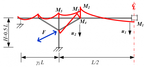
Further calculation yields the key displacements and internal forces. As shown in Figure 3, the red lines indicate the bending moments of key rods. Specifically, M1, M2, and M5 are the positive bending moment at the midspan, the negative bending moment at the junction between open and solid webs, and the negative bending moment on pier top, respectively; F and M4 are the axial force and bending moment at the junction between open and solid webs, respectively; M3=M2-M4; u1 and u2 are the vertical displacement in the open web, and at the junction between open and solid webs, respectively:
$\mathrm{u}_{1}=\Delta_{0}$
$u_{2}=\Delta_{1}$
$M_{1}=\frac{6 i_{0}}{l_{0}} \Delta_{0}-2 i_{0} \varphi_{1}-\frac{6 i_{0}}{l_{0}} \Delta_{1}-\frac{q l_{0}^{2}}{12}$
$M_{2}=-2 i_{1} \varphi_{1}+\frac{6 i_{1}}{l_{1}} \Delta_{1}-4 i_{1} \varphi_{2}-\frac{6 i_{1}}{l_{1}} \Delta_{2}+\frac{q l_{0}^{2}}{12}$
$M_{3}=4 i_{2} \varphi_{2}-\frac{6 i_{2}}{l_{2}} \Delta_{2}+2 i_{2} \varphi_{3}+\frac{6 i_{2}}{l_{2}} \Delta_{3}+\frac{q l_{0}^{2}}{12}$ (4)
$M_{4}=4 i_{7} \varphi_{2}-\frac{6 i_{7}}{l_{7}} \cos \theta_{7} \Delta_{2}+2 i_{7} \varphi_{5}+\frac{6 i_{7}}{l_{7}} \sin \theta_{7} \Delta_{5}+\frac{6 i_{7}}{l_{7}} \cos \theta_{7} \Delta_{6}+\frac{q l_{0}^{2}}{12}$
$M_{5}=2 i_{2} \varphi_{3}+\frac{6 i_{2}}{l_{2}} \Delta_{3}-4 i_{2} \varphi_{4}-\frac{6 i_{2}}{l_{2}} \Delta_{4}+\frac{q l_{0}^{2}}{12}$
$F=\frac{E A_{7}}{l_{7}} \sin \theta_{7} \Delta_{2}+\frac{E A_{7}}{l_{7}} \cos \theta_{7} \Delta_{5}-\frac{E A_{7}}{l_{7}} \sin \theta_{7} \Delta_{6}$
Figure 3. The key displacements and bending moments
The BACRF bridge boasts much smaller negative bending moment, midspan positive bending moment, and midspan displacement than T-shaped rigid frame or continuous beam bridges. Thanks to the good mechanical properties, the beam-arch composite structure has been widely applied in the construction of long-span bridges.
Despite the ability to rationalize the structural form, the classical structural mechanics model cannot effectively guide the design of actual bridges. Facing the complex and changeable real structures, the simplified theoretical model for structural mechanics have several limitations: unable to simulate reasonable changes in structural size; unable to simulate the construction process of the structure; unable to simulate the influence of steel beam; and difficult to consider the time-variation in material properties.
Therefore, theoretical analysis is far from enough to truly understand the force law of the BACRF bridge. It is of great necessity to adopt an accurate and efficient method to fully analyze more parameters and features of the structure.
4.1 Finite-element analysis on single parameters
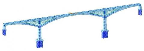
The Midas/Civil finite-element model was adopted for single parameter analysis (Figure 4).
Figure 4. The finite-element analysis model
(1) The influence of rise-span ratio
The rise-span ratio refers to the ratio of the height of the hollow beam on pier top (i.e., the vertical distance from the upper edge of the main beam to the lower edge of the main arch) to the length of the midspan. According to the design experience of conventional arch bridges, the rise-span ratio is a main determinant of structural rigidity, the force of the arch ring, and the horizontal thrust. Therefore, this section focuses on the impact of this parameter on the BACRF bridge, especially its impact on the overall rigidity of the structure.
Figure 5 presents the curves of displacement and internal force at key positions of the structure with the rise-span ratio under various working conditions.
Figure 5(a) shows the relationship between the rise-span ratio and the vertical deflection of the main beam at the midspan and arch-beam junction under moving load. With the growth in the rise-span ratio, the rigidity of the main beam gradually increased, while the deflection gradually decreased. The increasing/decreasing rate gradually slowed down with the growing rise-span ratio. Each curve had an obvious deflection point with significant slope change. From the engineering perspective, the rigidity of the BACRF bridge was too small, when the when the rise-span ratio was less than 10%; the midspan deflection of the structure was reduced by about 72%, as the rise-span ratio grew from 10% to 30%.
Figure 5(b) shows the relationship between main beam bending moment and rise-span ratio. With the growth in the rise-span ratio, the bending moments of the main beam at the middle fulcrum and midspan gradually declined; the bending moment at the arch-beam junction increased to a certain extent. However, the variation of the main beam bending moment mainly occurred when the rise-span ratio was smaller than 10%, indicating that the main arch has insufficient support for the main beam, as long as that ratio is below 10%.
Figure 5(c) shows the relationship of the bending moment of three members (main beam in open web section, main beam in solid web section, and main arch) with rise-span ratio. Coupled with the results from Figure 5(b), it is learned that the supporting effect of the main arch on the main beam increased with the rise-span ratio, but the main arch was still dominated by axial compression, which did not increase the bending moment of the arch rib.
Figure 5(d) shows the relationship between main arch axial force and rise-span ratio. Similar to the force features of conventional arch bridges, the main arch axial force reduced at a decreasing rate, with the growth in rise-span ratio.
In summary, the applicable rise-span ratio for the target bridge should be at least 10%. If conditions permit, a large rise-span ratio benefits the structural force. However, excessively large rise-span ratio will hinder the navigation under the bridge, push up the construction cost, and add difficulty to bridge construction. Thus, the suitable range of rise-span ratio for the bridge was determined as 15-20%.
Figure 5. The curves of displacement and internal force at key positions of the structure with the rise-span ratio under various working conditions
(2) The influence of open web ratio
The open web ratio refers to the ratio of the length of the open web (the horizontal distance between the arch-beam junction and the adjacent mid-pier) to the length of the midspan. In theory, the open web ratio is a calculation parameter controlled by beam height and rise-span ratio, rather
than an independent parameter. However, these geometric constraints were neglected to disclose the influence of the open web ratio on the structural force of BACRF, because of the prominence of this influence.
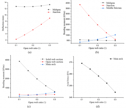
Figure 6 presents the curves of displacement and internal force at key positions of the structure with the open web ratio under various working conditions.
Figure 6(a) shows the relationship between the open web ratio and the vertical deflection of the main beam at the midspan and arch-beam junction under moving load. With the growth in the open web ratio, the midspan deflection did not change obviously, but the deflection at arch-beam junction grew linearly. The linear growth comes from the significant changes in the position of the junction, induced by the increase of open web ratio.
Figure 6(b) shows the relationship between main beam bending moment and open web ratio. With the growth in the open web ratio, the bending moment of the main beam at the midspan did not change obviously; the bending moment of the main beam at the middle fulcrum increased slightly by over 100% (as the open web ratio grew from 10% to 30%; the same below); the bending moment at the arch-beam junction plunged by 85%. The results suggest that the supporting position of the arch ring on the main beam moves closer to the midspan, with the increase of the open web ratio, but the supporting effect gradually decreases.
Figure 6(c) shows the relationship of the bending moment of three members with open web ratio. With the increase of the open web ratio, the main beam bending moment in the open web section did not change significantly, but that in the solid web section decreased significantly, mainly owing to the shortening of the equivalent span of the main beam in the solid web section; meanwhile, the bending moment of the arch rib rocketed up, indicating that the force of the main arch becomes unreasonable. Hence, the open web section should not be too long.
Figure 6(d) shows the relationship between main arch axial force and open web ratio. With the growing open web ratio, the main arch axial force gradually decreased by about 20%.
In summary, the growth in open web ratio has a certain impact on structural force, but the impact is not significant. Therefore, the open web ratio of the structure should be increased properly to improve economic benefits, without sacrificing the deflection in the triangular region. Of course, the designer must be aware of the upper limit of the open web ratio, after determining the span and rise of the BACRF bridge and the section height of each member.
Figure 6. The curves of displacement and internal force at key positions of the structure with the open web ratio under various working conditions
(3) Influence of side-to-middle span ratio
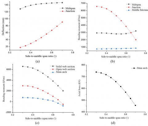
The side-to-middle span ratio refers to the ratio of the side span to the midspan. Due to the major impact of the main span on structural force, it is not suitable to explore the influence of the side-to-middle span ratio by changing the midspan. Thus, the side-to-middle span ratio was adjusted by changing the side span. In addition, the midspan length was set to the benchmark of 400m, because when the side-to-middle span ratio is small, the side-span open web structure will be difficult to arrange, if the side span is too short. Figure 7 presents the curves of displacement and internal force at key positions of the structure with the side-to-middle span ratio under various working conditions.
Figure 7(a) shows the relationship between the side-to-middle span ratio and the vertical deflection of the main beam at the midspan and arch-beam junction under moving load. With the growth in the side-to-middle span ratio, the midspan deflection slowly increased at a decreasing speed, while the deflection at arch-beam junction grew linearly. This is because, with the growing length of side span, the restraint effect of the side span rigidity on the mid-span decreases, and the displacement influence lines at different positions of the midspan obey different increasing trends.
Figure 7(b) shows the relationship between main beam bending moment and side-to-middle span ratio. With the growth in the side-to-middle span ratio, the bending moment of the main beam at the middle fulcrum did not change significantly; the bending moment of the main beam at the midspan remained stable when the ratio was smaller than 0.6, but slightly increased after the ratio surpassed 0.6; the bending moment at the arch-beam junction dropped deeply. Combined with the change in the deflection at the junction, the supporting effect of the arch rib on the main beam at the junction increases with side-to-middle span ratio.
Figure 7(c) shows the relationship of the bending moment of three members with side-to-middle span ratio. With the increase of the side-to-middle span ratio, bending moments of the main beam in the open web section and the solid web section, as well as the bending moment of the arch rib, were decreasing, due to the weakening of the supporting effect of the arch ring. Figure 7 (d) shows the relationship between main arch axial force and side-to-middle span ratio. With the growing side-to-middle span ratio (from 30% to 70%), the main arch axial force gradually decreased by about 40%.
In summary, the increase of the side-to-middle span ratio benefits the midspan force. When the side-span length was less than half the mid-span length, the main beam and arch rib of the midspan structure were under a large stress. Moreover, an excessively short side span limits the quadratic parabolic rising section at the midspan, making the structure unreasonable. In the meantime, an excessively large side span will lead to unfavorable side span force and a decrease in overall rigidity. In general, the side-to-middle span ratio should be set in the range of 0.5-0.6.
Figure 7. The curves of displacement and internal force at key positions of the structure with the side-to-middle span ratio under various working conditions
4.2 Fitting and comparison of deflection-span ratio
The previous analysis shows that the live load deflection of the structure depends on the following parameters of the arch-beam composite structure: rise, side span length, main beam height, main arch height, order of parabola, and mid-pier height. Among them, rise has far greater impact on structural rigidity than other parameters. Based on the results of parametric finite-element calculations, the calculated deflection of the BACRF bridge was fitted under live load. Then, the contribution coefficient of each influencing parameter was calculated by the optimization method under constraint conditions, and compared with the actual effects.
Considering the great influence of rise on structural rigidity, the following multivariate quadratic linear equation can be established:
$\frac{S_{k}}{L_{Z}}=\frac{1}{1000}\left[\left(\alpha_{1} \frac{F}{L_{Z}}+\alpha_{0}\right)\left(\beta_{1} \frac{L_{B}}{L_{Z}}+\beta_{2} \frac{H_{B}}{L_{Z}}+\beta_{3} \frac{H_{A}}{L_{Z}}+\beta_{4} T+\beta_{5} \frac{H_{T}}{L_{Z}}\right)+\gamma_{0}\right]$ (5)
where, Sk is the midspan deflection of a single lane under moving load; F is the rise of the BACRF bridge; LZ is the midspan length; LB is the side-span length; HB is the main beam height in open web section; HA is the main arch height in open web section; T is the shape factor of the lower edge of the BACRF bridge; HT is the mid-pier height of the BACRF bridge; α1 and α0 are the coefficient and constant to be fitted in the first factor formula, respectively; β1-β5 are the coefficients to be fitted in the second factor formula; γ0 is a constant to be fitted.
This form of fitting formula considers the need for nondimensionalization: s/LZ, F/LZ, and HB/LZ are the deflection-span ratio, the rise-span ratio, and the side-to-middle span ratio of the structure, respectively; HA/LZ and HB/LZ are the depth-span ratio of the main components; HT/LZ is the ratio of the pier height to the main span; T is a dimensionless parameter.
(1) Fitting method
To ensure the accuracy of the fitting equation, the following mathematical model was proposed:
$\min \sum_{i}^{m}\left(Y_{i}-y_{i}\right)^{2}$ (6)
where, yi and Yi are the deflection-span ratios of the i-th loading project calculated by the simplified formula and the finite-element analysis, respectively; m is the total number of loading conditions for fitting.
The various parameter features of the target BACRF bridge form a high-dimensional feature space. In that space, the deflection-span ratio of the structure, which depends on several characteristic parameters, is a high-dimensional point. In essence, this point is the hyperplane with the closest total distance to all data points. Hence, the fitting method by the hyperplane can be called the maximum hyperplane method.
Feasible sequential quadratic programming, as a relatively mature mathematical method, can transform the complex nonlinear constrained optimization into a relatively simple quadratic programming (QP) problem for iterative solution. The most prominent advantages over the other optimization algorithms include good convergence, high computational efficiency, and strong boundary search ability. Therefore, this method has been widely studied and applied in solving small and medium-sized problems.
(2) Calculation results
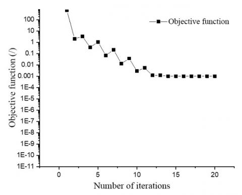
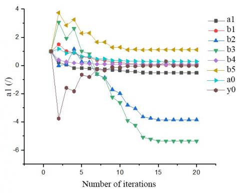
Based on the above solving method, the iterative variation in the objective function during the solving of the coefficients with a plug-in was recorded as Figure 8. The variation in each parameter to be fitted with the number of iterations is displayed in Figure 9.
Figure 8. The relationship between objective function and the number of iterations
Figure 9. The relationship between each parameter to be fitted with the number of iterations
The final formulas can be obtained as:
$\frac{s}{L_{z}}=\frac{1}{1000}\left(\xi_{1} \xi_{2}-0.0250\right)$ (7)
$\xi_{1}=0.2861-0.5251 \frac{f}{L_{Z}}$ (8)
$\xi_{2}=0.0267 \frac{L_{B}}{L_{Z}}-3.8492 \frac{H_{B}}{L_{Z}}-5.3618 \frac{H_{A}}{L_{Z}}$$+0.0903 T+1.1136 \frac{H_{T}}{L_{Z}}$ (9)
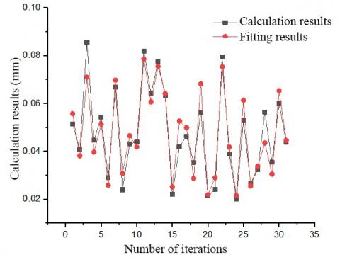
Figure 10. The fitting effect
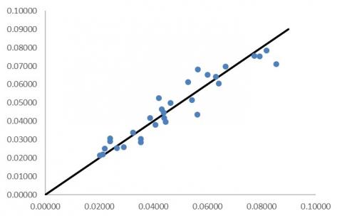
Figure 11. The scatter points of fitting errors
The parameters in formulas (7)-(8) have the same meanings as in formula (5). Figure 10 compares the results of simplified formula and those of finite-element analysis. Figure 11 presents the scatter points of fitting errors.
It can be seen that the fitting errors were mostly smaller than 10%, i.e., the fitting formula had an equivalent accuracy within ±10%. Therefore, the formula boasts good approximation and prediction effects.
This paper constructs a simplified mechanical model for BACRF bridge based on Mathematica theory, and builds up a refined finite-element model according to the actual structural size of Lijia Jialing River Bridge. On this basis, the authors discussed the influence of various parameters, e.g., span ratio, open web ratio, and side-to-middle span ratio, on the midspan displacement, arch-beam junction displacement, main beam bending moment, and main arch axial force of the bridge. The main conclusions are as follows:
(1) The mechanical expressions of the internal force and displacement were obtained for the key positions of the BACRF bridge.
(2) Judging by vertical deflection, rise-span ratio is the main influencing factor of midspan deflection; the impacts of open web ratio and side-to-middle span ratio are relatively small. However, the latter two parameters greatly affect the vertical deflection of the arch-beam junction, while rise-span ratio has a limited impact on the vertical deflection at that position.
(3) Judging by main arch axial force, when the rise-span ratio is less than 0.1, the supporting effect of the main arch on the main beam is insufficient, the main beam is subject to excessively large force, and the main arch is subject to excessively small force. In actual projects, the rise-span ratio of the BACRF bridge should be at least 0.1.
(4) The beam height of the BACRF bridge, which has a limited effect on overall rigidity, should be determined according to the local force requirements of the beam structure. In general, the height of the main arch beam should be equivalent to the height of the main beam.
(5) Based on the analysis of the above parameters, the calculation formula of the deflection-span ratio was proposed for the BACRF bridge. This formula fully considers the influence of rise-span ratio, side-to-middle span ratio, main beam depth-span ratio, main arch depth-span ratio, order of parabola, and the relative height of the main pier over the deflection-span ratio of the BACRF bridge. The results calculated by the formula deviated by less than 10% from the finite-element results, indicating that the formula can be used to guide the bridge design.
This work was supported by Technology Innovation Project of Chongqing Municipal Science and Technology Bureau (Grant No.: cstc2018jscx-mszdX0083), Technology Research and Development Project of China State Construction Engineering Corporation (Grant No.: CSCEC-2018-Z-17), and Technology Research and Development Project of China Construction Fifth Engineering Bureau (Grant No.: CSCEC-2018-04).
[1] Zhang, X., Liang, N., Lu, X., Gu, A., Shan, J. (2019). Optimization method for solving the reasonable arch axis of long-span CFST arch bridges. Advances in Civil Engineering, 2019: 7235656. https://doi.org/10.1155/2019/7235656
[2] Salonga, J., Gauvreau, P. (2014). Comparative study of the proportions, form, and efficiency of concrete arch bridges. Journal of Bridge Engineering, 19(3): 04013010. https://doi.org/10.1061/(ASCE)BE.1943-5592.0000537
[3] Hu, D.L., Chen, D.S., Zhao, X.Y., Gong, J.P., Li, Y. (2016). Construction control of cantilever casting of long span reinforced concrete arch bridge. Journal of Traffic and Transportation Engineering, 16(1): 25-36. https://doi.org/10.19818/j.cnki.1671-1637.2016.01.004
[4] Li, G.P. (1999). Performance and characteristic of continuous composite arch bridge. Bridge Construction, (1): 10-13. https://doi.org/10.3969/j.issn.1003-4722.1999.01.004
[5] Jin, C.D. (2001). Design Research and Practice of Prestressed Concrete Beam-Arch Composite Bridge. Beijing: China Communications Press.
[6] Bransch, M. (2017). Suggestions for the construction of composite arches at tied arch bridges. Stahlbau, 86(3): 269-278. https://doi.org/10.1002/stab.201710464
[7] Gou, H.Y., Pu, Q.H., Zhou, Y., Hong, Y. (2015). Arch-to-beam rigidity analysis for V-shaped rigid frame composite arch bridges. Steel Compos Struct, 19(2): 405-416. https://doi.org/10.12989/scs.2015.19.2.405
[8] Gou, H., Pu, Q., Shi, X., Shi, Z. (2015). Local stress and nonlinear mechanical behaviors of the V-shape pier-girder joint based on model test. Advances in Structural Engineering, 18(12): 2193-2205. https://doi.org/10.1260/1369-4332.18.12.2193
[9] Rovira, M.R., Tomàs, J.G. (2018). Construction of the Nelson Mandela Bridge in Barcelona. Structural Engineering International, 28(3): 376-380. https://doi.org/10.1080/10168664.2018.1453761
[10] Xiao, Y.B. (2013). Analysis and study on structure stress in construction process of v-shaped rigid frame continuous beam composite arch bridge. Urban Roads Bridges & Flood Control, (11): 69-71, 75. https://doi.org/10.16799/j.cnki.csdqyfh.2013.11.022
[11] Zong, X., Wu, Y.Y., Peng, Y.C., Chen, Z.G. (2010). Design and calculation of cross-leg beam joint of Beipanjiang bridge. Journal of China & Foreign Highway, 30(4): 183-186. https://doi.org/10.14048/j.issn.1671-2579.2010.04.082
[12] Yang, S.Y. (2013). Comparison of open-web and ordinary rigid frame bridge. Wuhan: Huazhong university of Science & Technology, 19-46.
[13] Lu, B. (2014). The performance of opened-web continuous rigid frame bridge. Xi’an: Chang’an University.
[14] Lu, B., Wang, K.H., Li, G.C., He, S.H. (2014). Influence of design parameters on key section internal force in open-web continuous rigid frame bridge. Journal of Highway and Transportation Research and Development, 31(12): 73-77. https://doi.org/10.3969/j.issn.1002-0268.2014.12.012
[15] Han, H.J., Huang, K.Q. (2011). Construction techniques for triangle area of a 290m span open-web continuous rigid-frame bridge. Bridge Construction, (3): 81-84.
[16] Huang, K.Q., Peng, X.M. (2011). Analysis of mechanical behavior of a prestressed concrete open-web continuous rigid-frame bridge in construction process. Bridge Constuction, (3): 40-43.
[17] Peng, Y.C., Dong, X., Liang, N., Deng, Z.Q. (2016). Model test of the Beipan River’s new open-web continuous rigid frame bridge corner node. Journal of Shangdong University (Engineering Science), 46(6): 113-119. https://doi.org/10.6040/j.issn.1672-3961.0.2016.137
[18] Ding, Y.C., Xiang, Z.F., Li, Y.Y., Zhang, X.S., Zhou, Y. (2020). A practical and safe optimization method for temporary cable layout on the upper beam of beam-arch composite rigid frame bridge. International Journal of Safety and Security Engineering, 10(1): 89-95. https://doi.org/10.18280/ijsse.100112