Anna Faura-Pujol | Marcos Faundez-Zanuy*![]() | Aleix Moral-Viñals | Josep López-Xarbau
| Aleix Moral-Viñals | Josep López-Xarbau![]()
© 2023 IIETA. This article is published by IIETA and is licensed under the CC BY 4.0 license (http://creativecommons.org/licenses/by/4.0/).
OPEN ACCESS
The present study pursues to determine the optimal operation range of a specific screen-based eye-tracker, the Tobii X2-30, regarding the variation of precision and accuracy in measures. Furthermore, a connection setup to operate a collaborative robot (cobot) Omron TM5-700 by means of this eye-tracker will be presented. The possibility to operate a collaborative robot by gaze can be used as a third arm, which allows human beings to do more sophisticated activities, as well as making the manipulation of dangerous or perilous substance easier and safer. When developing new technological tools, we have mainly two options. The first one consists on a specifically designed hardware. While in this option, the engineer has full control over the device and can fit it to the specific requirements; in general, it will be a time consuming and expensive development. A second drawback is the limited possibility of researchers from other countries to construct an exactly equal device and replicate the experiments. The second option consists on adopting an existing commercial hardware, which probably has not been designed for the specific application in mind. The main advantage is the easy adaptation of this solution by other researchers, who only need to purchase the same commercial device and follow the recommendations. However, the main drawback of this approach is that the developers must test the device and check that it can be used for the new application. The goal of this paper is to test a commercial device and provide usability recommendations for a new application such is the movement of a robotic arm using eye-tracking. This paper includes the results from three experiments, which assess the final conclusion on the best performance positioning of the user regarding the Tobii X2-30 eye-tracker, in x, y, and z coordinates. When it comes to its implementation with the cobot, the outcome of a practical demo and experimental setup is also presented. This last one consists of accuracy measurements, where the control of the position of the cobot is defined by means of gaze, which defines a set of points in (x,y) plane. Later on, the robot picks up an ink-pen and draws a graph in a piece of paper. This drawing involves connecting these pre-defined dots by straights lines. To this end, a set of figures (parallelogram, pentagon, etc.) have been acquired and compared with the desired printed images on the PC screen.
accuracy, collaborative robot, eye-tracker, gaze, precision
Eye-tracking is a technology with applications in a large set of life areas. Soon after the COVID-19 arose, in 2020, the eye-tracking market was valued at USD 664.9 million. Moreover, it is expected to reach USD 4.86 billion by 2030, which implies growths at a Compound Annual Growth Rate (CAGR) of 22.4% during the forecast period [1].
Eye-tracking technology is growing quickly in the very recent years. A Google Scholar search of the terms ‘eye-tracking’ and ‘safety’ yields 38,000 results. Of these, 17,600 were published in the 2017-2021 period. Nowadays, health and retail are the two areas where the penetration of this technology’ use is the highest. However, the tendency is that, in the forthcoming years, automotive, neuromarketing, and industry 4.0 will stand out.
Eye-tracking technology can be very useful for a wide variety of safety and security applications. In the impending years, predictions suggest that augmented reality and virtual reality will be the most recurring applications of this technology, as well as its incorporation into mobile devices, entertainment, and gaming or contactless biometric solutions. Furthermore, in the context of the COVID-19 pandemic, new insights have emerged. Touch-free machines, with which the user can operate without the need to touch a surface, are more desirable, as the risk of contagion decreases very significantly.
In the light of the above, some specific uses of eye-tracking technologies are described below.
Several studies have recently focused on how eye-tracking devices can help a user perform different tasks when it comes to its interaction with a robot. An example of this can be found in [15], where an eye-tracker collaborates with a robotic arm to allow individuals with Severe Speech and Motor Impairment (SSMI) to manipulate objects. In addition, this robot is able to perform some tasks that help them in their rehabilitation process.
Regarding a similar field of application, an air pressure actuator can be regulated using eye-tracking techniques. This has currently been implemented as a physiotherapy device among users that present weakness in their forearm [16].
Other examinations have concluded that eye-tracking techniques are able to control telepresence robots [17], but this still remains an area that requires future work and investigation.
The aim of this paper is to determine the optimal operation range of a specific screen-based eye-tracker, the Tobii X2-30, regarding the variation of precision and accuracy in measures. Further applications of this analysis in the health area include the eyesight monitorization of patients suffering from Parkinson Disease (PD). Researchers have studied the impact of visual feedback on the writing size of this group [21], which has led to the idea that there could be something in common when it comes to the vision of PD patients, worthy of study.
In addition, we setup the communication between this eye-tracker and a cobot, or collaborative robot, and we perform a set of experiments regarding drawing performance based on gaze. This is a simple environment test that has already been explored by different authors using different setups [22]. Handwriting analysis has a wide range of applications in e-security and e-health [23], and a large set of tasks can be performed [24]. There are great possibilities when it comes to combining handwriting analysis and eye-tracking in e-health and e-security, which ought to be developed in the forthcoming years. Therefore, we consider interesting to describe the setup of the system due to the fact that a large number of robots and eye-trackers exist and its interconnection is not trivial and must be ad hoc designed.
In this paper, we want to perform several experiments in order to be able to determine the user’s optimal exact position (in x, y, and z coordinates) regarding the eye-tracker. Moreover, we want to define mobility margins within which the user can move without compromising the validity of the obtained results.
2.1 Experimental setup description
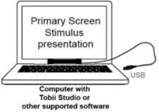
The Tobii X2-30 is a screen-based eye-tracker that has been designed to be connected to a PC, below its screen. In our case, it has been attached to a laptop as shown in Figure 1.
The data gathering from the different experiments have been carried out with the Tobii Pro Lab software running in the laptop, which offers a complete toolset for this purpose.
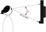
When it comes to the user’s position regarding the eye-tracker, we have established the coordinate system in Figure 2. As it can be seen in the ground plan view, it is eye-tracker based.
Figure 1. Tobii X2-30 attached to a laptop
Figure 2. Coordinate system for experiments
2.2 Experiments and results
We have designed a set of three simple experiments in order to determine the optimal y, x, and z position, respectively. All experiments have been carried out ensuring that the gaze angle (α) never exceeded 36º, according to manufacturer (see Figure 3). Before the start of each of the experiments that will be presented, a process of calibration has been made. Although with the Tobii Pro Lab software it is simple and quick, if not done, the accuracy of results could be compromised.
Figure 3. Gaze angle
Data recorded by the Tobii Pro Lab software can be either monocular, if it is based on data from the subject’s dominant eye only, or binocular, when the data shown are the average of both eyes. In this paper, all data are binocular.
2.2.1 Accuracy and precision
The results given by the Tobii Pro Lab software are the accuracy and precision degrees between the exact position of several points that appear on the screen, which ought to be followed by the user’s sight and the gaze point that the eye-tracker captures in each case.
Figure 4. Concepts of accuracy and precision
By accuracy we understand the closeness of the measurements to a specific value, normally referred to the closeness of the measurements to the real or accepted value. Precision stands for closeness of the measurements to each other. Figure 4 is bound to illustrate this. Here, the actual value is represented with a green circle on the origin x axis, while 30 experimental measures are represented by blue circles in the x axis.
Both accuracy and precision are error measures: the lower the accuracy and precision of a measurement are, the better. In order to clarify both concepts, some conceptual graphs coming from normal distributions are shown in Figure 5, where the real value is that in green.
Figure 5. Accuracy and precision example
2.2.2 Experiment 1: y axis position
Figure 6. Accuracy results when varying the y distance (Experiment 1)
Figure 7. Precision results when varying the y distance (Experiment 1)
First, we wanted to see the impact in precision and accuracy measurements when the user moves forward and back. In other words, when he/she varies his/her y distance to the eyetracker, according to the established coordinate system.
The Tobii manufacturer affirms that this eye-tracker can record data in a range of 40-90 cm between the eye-tracker and the subject. Nevertheless, the experiments’ results have proven that y distances equal or greater than 76.0 cm, as well as distances equal or less than 46.8 cm, are out of this device’s range.
In order to determine the optimal y position of the user towards the eye-tracker, for each y distance, three iterations have been made. The average accuracy and precision results of these have been plotted as shown in the following graphs, using the maximum, minimum, and average value in each case.
The eye-tracker incorporates several cameras. The purpose of these cameras is to permit the eye detection and measurement of relevant information for eye-tracking. When developing an eye-tracker, the cameras are selected for a specific feature. Normally, they are fixed cameras, with no possibility to automatically focus an object at a large set of focal distances. Thus, in Figures 6 and 7, we detect the optimal operational range of the cameras.
The manufacturer affirms that the best performance of this eye-tracker is in the y range [60, 65] cm. In the light of the results, one can see that the lowest accuracy and precision are achieved from 55 to 65 cm. All in all, we confirm that the best performance of the eye-tracker is carried out from a relative distance of 55 to 65 cm between the user and the eye-tracker. With greater distances, the accuracy and precision both increase, and the same happens with very short distances.
2.2.3 Experiment 2: x axis position
Second, once the best performance area in the y axis has been determined, the aim of this experiment is to quantify the real difference in the eye-tracker measurements when the user moves in the x axis, so if he/she moves right to left.
Having seen the best performance range in the y axis, in this second experiment we have set the user to be seated at y=60/63/65 cm. For each of these three distances, we have registered data from the eye-tracker when the subject moved from x=15-cm to x=15 cm.
Carrying on with the methodology in Experiment 1, three iterations have been done in each case. The average accuracy and precision results of these have been plotted as shown in the following graphs, using the maximum, minimum, and average value in each case. The average value is represented by a dot, while the maximum and minimum values are indicated by the top and the bottom of the straight line that passes through the dot.
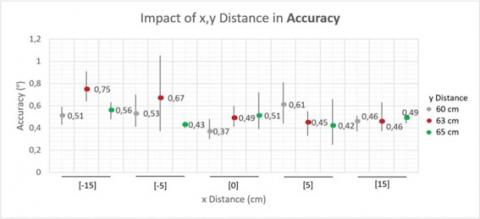
If the user moves in the y direction within a 10-cm eye-tracker-centered margin, the accuracy goes from 0.37º to, at most, 0.67º. The average accuracy within the best performance area is 0.6º. According to Tobii manufacturer, one degree accuracy corresponds to an average error of 12 mm on a screen at a distance of 65 cm [25]. Therefore, the worst accuracy will be of, approximately, 8 mm. This can also be calculated with trigonometry, considering the gaze angle and y distance (both known parameters).
If we now take a bigger x range, from x =-15 cm to x=15 cm, this impinges on the accuracy, as expected. At a distance of 60 cm this is not significant, but the accuracy gets worse as the x distance increases, achieving 0.75º, at most, at 63 cm. This will be, approximately, 9 mm.
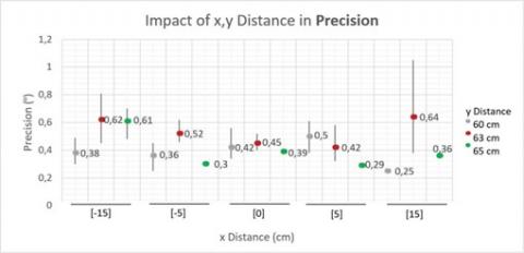
If the user moves in the y direction within a 10-cm eye-tracker-centered margin, precision goes from 0.39 to 0.52, at most, which is still lower than the maximum accuracy in these conditions. The worst accuracy will be of, approximately, 6 mm. In average within this range, it is exactly 0.47º.
Similarly to what happened with accuracy, taking a bigger range impinges on the precision. At a distance of 60 cm this is not significant, but precision gets worse as the x distance increases, achieving 0.64º, at most, at 63 cm, which is, approximately, 7.7 mm.
In the light of the results, both precision and accuracy get worse if the user can move within a 30-cm centered margin in reference to the eye-tracker (so with x distances of 15 to 15 cm) (as shown in Figure 8). Whenever possible, the eye-tracker’s results will be better if the user does not move, or if he/ she does not move a lot (so if he/she is kept in a 10-cm centered margin in reference to the eye-tracker). However, it would not be realistic to think that the user will be seating still all the time due to the fact that he/she can easily move 10 cm around the centered position (5 cm to the right or left) without even noticing it. That is why there should be no significant change in the obtained results, and we have proved this true. Even so, the least the user moves, the better.
Figure 8. Accuracy results when varying the x and y distance (Experiment 2)
Figure 9. Precision results when varying the x and y distance (Experiment 2)
2.2.4 Experiment 3: z axis position
The last experiment pursued the determination of the optimal height at which the subject should be seated in order to achieve better accuracy and precision results. In this case, a new variable had to be factored in: the type of chair. Up to this point, the previous experiments had been carried out while the user was seated in a normal, four-legged static chair. But for this third experiment, the subject has been seating on an office chair on wheels, so the height could be modified throughout the data gathering process. Particularly, the chosen chair and its height parameters that are relevant for this experiment can be seen in Figure 9.
In addition, the eye-tracker’s z position, so the distance from this device to the floor during Experiment 3, was 77 cm.
It must be said that, in Experiment 3, the data recording took place in a different physical environment than the one used for Experiments 1 and 2. Although it was also an indoor office environment, it had less natural light and a little more artificial light. This is important because, according to Tobii manufacturer, when the illumination in the lab changes, the size and shape of the pupil is affected. Unless compensated for, this may cause a significantly reduced accuracy [26]. This comes to say that the accuracy or precision values obtained in this experiment should not be compared with the ones obtained in the previous experiments, as they are bound to differ. Nevertheless, they are still valuable because the aim of this experiment is to see the tendency of the accuracy and precision variation as height increases, in the same conditions (as shown in Figure 10).
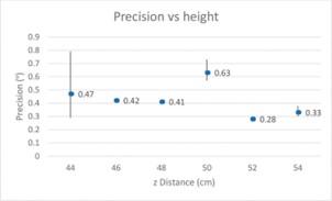
The results have been plotted and are shown in Figures 11 and 12. Note that z distance is the distance from the floor.
Figure 10. Height parameters of the office chair on wheels used for Experiment 3
The best height for optimal performance of the eye-tracker is 52 cm. When the user is sat on a chair that is elevated 52 cm above the floor, the accuracy and precision are at its best (their values are small). If this altitude over the floor cannot be guaranteed exactly, it is better to position the user between z = 46 cm, and z = 48 cm than to position him/her at z = 50 cm. At 50 cm, both the accuracy and precision are the worst.
Figure 11. Accuracy results when varying the z distance (Experiment 3)
Figure 12. Precision results when varying the z distance (Experiment 3)
After having analyzed the optimal operation range of the eye-tracker, we will configure a setup based on the devices available in our lab: a collaborative Omron TM5-700 robot and a Tobii X2-30 eye-tracker attached to a laptop.
3.1 Elements description
Our system uses two different computers between which we have established an Ethernet connection that enables their communication. Figure 13 shows the experimental setup, which consists of the following parts:
1. OMRON Cobot-arm model TM5-700. Collaborative robots are designed to work safely with human operators thanks to technologies like force feedback, low-inertia servo motors, elastic actuators, and collision detection technology that limit their power and force capabilities to levels suitable for contact. The safety standard ISO 10218-1, ISO 10218-2, and technical specification ISO TS-15066 define the safety functions and performance of the collaborative robot. We have used this specific robot as it was the only collaborative robot available in our laboratory.
2. 3D grip attached to the cobot to hold the marker pen that performs the drawing on the surface area. The marker pen that has been chosen is a standard one, as the robot can use the grip to hold pens that may have different thicknesses.
3. Drawing surface, the size of which is a standard DINA3. Here, the collaborative robot will draw by moving its arm.
4. Cobot controller screen. The computer executes a software that is programmed with the software OMRON TMFlow, which is a graphical Human-Machine Interface. This makes the programming of a specific algorithm easier. It should be noted that where the collaborative robot is operated by a dedicated computer hidden in a box below the cobot.
Figure 13. Experimental setup including: (1) cobot-arm TM5-700, (2) 3D grip, (3) DIN A3 drawing surface, (4) cobot controller screen, (5) cobot remote control, (6) Tobii X2-30, (7) eye-tracker laptop, (8) Ethernet connection.
5. Cobot remote control, also known as robot stick. It is vital to start or stop the instructions’ reception by the robot.
6. Tobii X2-30 eye-tracker, which is attached to the bottom part of the laptop screen.
7. Eye-tracker laptop, which operates the eye-tracker software programmed in Phyton.
8. Ethernet connection for the communication between computers. It will be in charge of sending the instructions from the eye-tracker computer to the cobot computer.
3.2 Technical block description
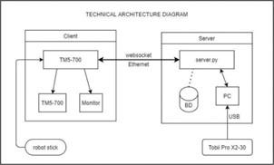
The technical scheme on the communication data flow between the eye-tracker and the cobot can be seen in Figure 14, which illustrates the server–client architecture. The server provides the data acquired by the eye-tracker while the client is the cobot.
Further detail on the communication between the eye-tracker and collaborative robot can be found in [27].
Figure 14. Technical scheme of communication data flow between eye-tracker and cobot.
3.3 Experiments and results
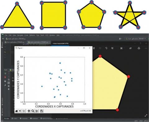
Our main goal is to examine the system. To do so, some exercises have been designed, consisting of the drawing of a simple set of figures that can be seen in Figure 15.
The process begins when the subject selects which figure he or she wants to draw. Then, when the system shows it to the user and he or she will look at all of its corners (marked in red in Figure 15), while the eye-tracker acquires the set of points. Feel free to visit the following YouTube link, where we have included a demonstration of the system operation: https:// youtu.be/U6KYuhel9Tk.
Once the system has been tested, its application in more realistic and daily life situations is analogous. It could be easily adapted for handicapped people or in industrial environments that deal with perilous or hazardous substances, as it has been explained in previous sections of this paper. Nevertheless, this is beyond the goal of this paper, as we do not have access to these scenarios.
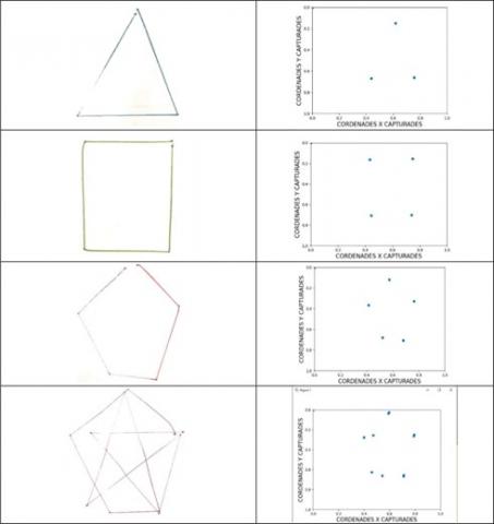
Figure 16 shows the experimental results performed by the cobot on a DINA3 paper. On the left column, we can observe the result of the drawing performed by the cobot. On the right column, it is depicted the acquired points by the eye-tracker when the user looks at the corners of the desired image (from top to bottom: triangle, rectangle, pentagon, and star inside a pentagon). In our software design, the starting and ending point are marked separately by the user. For this reason, the figures look opened and not closed. In case of programming the application, to perform a line connecting the last acquired point to the first one, the figure would be closed.
Table 1 highlights the accuracy and precision of the system (accuracy refers to how close a measurement is to the true or accepted value. Precision refers to how close measurements of the same item are to each other).
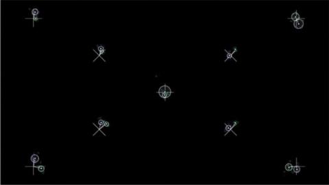
Table 1 has been obtained averaging 10 different users (five males and five females). All the users were not eye-tracker skilled users. In fact, most of them used the eye-tracker for the first time. Figure 17 shows the calibration points acquired by the eye-tracker. They cover the four screen corners as well as the center.
Based on the experimental results, we can conclude that the accuracy is 5.5 mm, which should be compared with the whole dimension of the drawing. For large drawings, say about 20 cm, it represents a small relative error (2.8%). However, for small size drawings, the error can compromise the quality of the final result.
Figure 15. Top, from left to right: triangle, rectangle, pentagon, and star figures presented on the screen of the eye-tracker. Bottom: user interface with several acquired dots
Figure 16. Triangle, rectangle, pentagon, and star inside a pentagon. Drawing performed by the robot (left column) and points acquired by the eye-tracker (right column)
Table 1. Accuracy and precision of measurements (SD=standard deviation, RMS=root mean square)
|
Validation accuracy |
Validation precision (SD) |
Validation precision (RMS) |
||||||
|
degrees |
pixels |
mm |
degrees |
pixels |
mm |
degrees |
pixels |
mm |
|
0.70º |
22 |
5.5 |
0.22º |
7 |
1.7 |
0.33º |
10 |
2.6 |
Figure 17. Calibration points acquired by the eye-tracker
Worth to mention that the user has performed the tasks without a lot of intensive training, and it has been tested with several users. All of them agree that the system is easy-to-use.
Regarding the optimal operation range of the Tobii X2-30 screen-based eye-tracker, the different experiments that have been carried out conclude that accuracy and precision are at its best when the user is located at a y distance in the range of 55-65 cm. The less he/she moves, the better, because when the subject is centered towards the eye-tracker the measurements are more accurate than if he/she is not. Nevertheless, if he/she moves 5 cm to the right or left in the x axis, the results are not compromised. At last, when it comes to the z distance, the optimal is 52 cm.
Furthermore, an experimental setup connecting this eye-tracker to a collaborative robot OMRON TM5-700 has also been presented. In this process, the most challenging part has been the communication between both elements. Once this has been solved, it should not be difficult to adapt this system in a large number of quotidian applications where a robotic arm can be controlled by the user’s gaze in a wide variety of fields including safety in industrial environments or health, among others. Although using a different robot and eye-tracker would require a new setup, it is our belief that this paper ought to be valuable concerning the new system design.
Experimental calibration data will be freely available contacting the authors as well as in arxiv.org data repository.
This work has been funded by Spanish grant Ministerio de ciencia e innovación PID2020-113242RB-I00.
[1] Eye Tracking Market by Type, Application, and Industry Vertical-Global Opportunity Analysis and Industry Forecast, 2021-2030. June 2021.
[2] Jeelani, I., Han, K., Albert, A. (2018). Automating and scaling personalized safety training using eye-tracking data. Automation in Construction, 93: 6377. https://doi.org/10.1016/j.autcon.2018.05.006
[3] Hasanzadeh, S., Esmaeili, B., Dodd, M.D. (2017). Measuring the impacts of safety knowledge on construction workers’ attentional allocation and hazard detection using remote eye-tracking technology. Journal of Management in Engineering, 33(5): 04017024. https://doi.org/10.1061/(ASCE)ME.1943-5479.0000526
[4] Daniel, M.M., Pingali, S., Panuwatwanich, K., Stewart, R.A., Mohamed, S. (2021). Application of eye tracking technology in aviation, maritime, and construction industries: a systematic review. Sensors, 21(13): 4289. https://doi.org/10.3390/s21134289
[5] Carr, D.B., Grover, P. (2020). The role of eye tracking technology in assessing older driver safety. Geriatrics, 5(2): 1-14. https://doi.org/10.3390/geriatrics5020036
[6] Vetturi, D., Tiboni, M., Maternini, G., Bonera, M. (2020). Use of eye tracking device to evaluate the driver’s behaviour and the infrastructures quality in relation to road safety. Transportation Research Procedia, 45: 587-595. https://doi.org/10.1016/j.trpro.2020.03.053
[7] Rjabovs, A., Palacin, R. (2019). Investigation into effects of system design on metro drivers’ safety-related performance: an eye-tracking study. Urban Rail Transit, 5: 267-277. https://doi.org/10.1007/s40864-019-00115-1
[8] Khan, M.Q., Lee, S. (2019). Gaze and eye tracking: Techniques and applications in ADAS. Sensors, 19(24): 5540. https://doi.org/10.3390/s19245540
[9] Le, A.S., Suzuki, T., Aoki, H. (2020). Evaluating driver cognitive distraction by eye tracking: From simulator to driving. Transportation Research Interdisciplinary Perspectives, 4: 100087. https://doi.org/10.1016/j.trip.2019.100087
[10] Gruden, C., Otković, I.I., Šraml, M. (2021). Safety analysis of young pedestrian behavior at signalized intersections: an eye-tracking study. Sustainability, 13(8): 4419. https://doi.org/10.3390/su13084419
[11] Babić, D., Babić, D., Fiolić, M., Ferko, M. (2021). Factors affecting pedestrian conspicuity at night: Analysis based on driver eye tracking. Safety Science, 139: 105257. https://doi.org/10.1016/j.ssci.2021.105257
[12] Peysakhovich, V., Lefrançois, O., Dehais, F., Causse, M. (2018). The neuroergonomics of aircraft cockpits: The four stages of eye-tracking integration to enhance flight safety. Safety, 4(1): 8. https://doi.org/10.3390/safety4010008
[13] Teja, R., Chadalavada, H.A., Schindler, M., Palm, R., Lilienthal, A.J. (2020). Bi-directional navigation intent communication using spatial augmented reality and eye-tracking glasses for improved safety in human-robot interaction. Robotics and Computer-Integrated Manufacturing, 61: 101830. https://doi.org/10.1016/j.rcim.2019.101830
[14] Dahmani, M., Chowdhury, M.E.H., Khandakar, A., Rahman, T., Al-Jayyousi, K., Hefny, A., Kiranyaz, S. (2020). An intelligent and low-cost eye-tracking system for motorized wheelchair control. Sensors, 20(14): 3936. https://doi.org/10.3390/s20143936
[15] Krishna Sharma, V., Murthy, L., Singh Saluja, K., Mollyn, V., Sharma, G., Biswas, P. (2020). Eye gaze controlled robotic arm for persons with SSMI. Journal of Technology and Disability, 32(3): 179-197.
[16] Oguntosin, V., Abdulkareem, A. (2020). Design of a pneumatic soft actuator controlled via eye tracking and detection.
[17] Zhang, G., Hansen, J.P. (2019). Accessible control of telepresence robots based on eye tracking. In Proceedings of the 2019 ACM Symposium on Eye Tracking Research & Applications.
[18] Marandi, R., Gazerani, P. (2019). Aging and eye tracking: in the quest for objective biomarkers. Future Neurology, 14(4). https://doi.org/10.2217/fnl-2019-0012
[19] Blondon, K., Wipfli, R., Lovis, C. (2015). Use of eye-tracking technology in clinical reasoning: a systematic review. In Digital Healthcare Empowering Europeans, 90-94. https://doi.org/10.3233/978-1-61499-512-8-90
[20] Hutton, J.T., Nagel, J.A., Loewenson, R.B. (1984). Eye tracking dysfunction in Alzheimer-type dementia. American Academy of Neurology, 34(1): 99. https://doi.org/10.1212/WNL.34.1.99
[21] Potgieser, A.R., Roosma, E., Beudel, M., de Jong, B.M. (2015). The effect of visual feedback on writing size in Parkinson’s disease. Parkinson’s Disease, 2015: Article ID 857041. https://doi.org/10.1155/2015/857041
[22] Scalera, L., Seriani, S., Gallina, P., Lentini, M., Gasparetto, A. (2021). Human-Robot Interaction through eye tracking for artistic drawing. Robotics, 10(2): 54. https://doi.org/10.3390/robotics10020054
[23] Faundez-Zanuy, M., Fierrez, J., Ferrer, M.A., Diaz, M., Tolosana, R., Plamondon, R. (2020). Handwriting biometrics: Applications and future trends in e-security and e-health. Cognitive Computation, 12: 940-953. https://doi.org/10.1007/s12559-020-09755-z
[24] Faundez-Zanuy, M., Mekyska, J., Impedovo, D. (2021). Online handwriting, signature and touch dynamics: Tasks and potential applications in the field of security and health. Cognitive Computation, 13: 1406-1421. https://doi.org/10.1007/s12559-021-09938-2
[25] Tobii Pro X3-120 Eye Tracker. (2016). Product Description.
[26] Tobii Pro X3-30 Eye Tracker. (2013, January). Product Description.
[27] Faundez-Zanuy, M., Moral-Viñals, A., Lopez-Xarbau, J. (2021). Use of eye-tracking to control a cobot movement: Results coming from the application of Tobii Pro X2-30 to an Omron Tm5-700 Robot. WIT, 206: 12. https://doi.org/10.2495/SAFE210201