Kazuo Matsuura* | Koh Mukai | Mikael Andersen Langthjem![]()
© 2023 IIETA. This article is published by IIETA and is licensed under the CC BY 4.0 license (http://creativecommons.org/licenses/by/4.0/).
OPEN ACCESS
The sound produced when jets issued from a circular nozzle collide with a downstream ring coaxial with the jet is called a ring tone. The ring tone is investigated through experiments and direct sound computations. The inner diameters of the circular nozzle exit and the ring are both 30 mm. In the experiments, the frequency spectra of the ring tone are measured for various impingement lengths of 20–40 mm and jet velocities of 5–15 m/s. Measured data exhibit typical properties of self-sustained oscillations such as linear rise in peak frequency as the rise of the jet speed, multiple series of peaks, and mode jumps. In the computations, points discretely representing volumetric vortical regions are divided into locally connected groups of points that are separated from each other. This clustering enables the extraction of volumetric vortical regions in three-dimensional flow fields based on attributes defined on each point and tracking vortex structures selectively. By identifying strong vortex structures, the onset of self-sustained feedback oscillations in the ring tone is clarified from the view point of the throttling mechanism originally proposed for the hole tone, i.e., the coupling between the mass flow through the ring, vortex impingement, and global pressure fluctuation.
aeroacoustics, direct sound computation, hole tone, ring tone, wind tunnel
The ring tone is a kind of feedback sound. The pressure waves are generated when vortices from a circular nozzle collide with a downstream obstacle, propagate upstream, and regulate the timing of further vortex ejection from the nozzle [1-4].
The tone is a dipole sound with an efficiency scaling of the third power of the jet Mach number; the dipole strength is equal to the unsteady force on the ring [4]. These dipoles radiate in the direction of the jet axis [3]. Chanaud and Powell [5] studied the ring tone with a torus with an inner diameter of 5 mm formed from copper wire with a diameter of 1.5 mm. They varied the edge distance at a constant Reynolds number and also varied the Reynolds number at a constant edge distance. They found that at large spacing ratios, the holeand ring-tone minimum-edge-distance contours have similar shapes but affected an edge-tone contour. At small spacing ratios, the minimum-edge-distance contour for the ring-tone system deviates markedly from other contours, there being folds in the contours. It was observed that the folds are seen to be related to jumps at higher Reynolds numbers. Obata et al. [6] experimentally investigated the ring tone. They found that multiple frequency components have substantial amplitudes compared to the fundamental frequency component, and showed that the lowest frequency component can interact with the fundamental component either to reinforce itself or to produce an additional frequency component.
Although edge and hole tones have been investigated relatively in detail [3, 7-10] among feedback sounds, the details of the ring tone, such as flow oscillation due to vortex impingement on the ring and the difference between the ring and hole tones, are unknown except for the description mentioned above. Therefore, in this study, a ring-tone system is developed, the frequency spectra of the ring tone are measured for various impingement lengths and jet velocities, and the sound generation mechanism is investigated through a direct sound computation. In the measurements, the ring tone is compared with the hole tone, which is generated when a metal plate with a hole is installed instead of the ring. To our best knowledge, this study is the first case of applying a direct computation to the ring tone [11]. Vortex motion and interaction with a ring play a key role in ring tone. However, conventional iso-surface visualization of vortices is not suitable for visualizing vortices hidden in the dense cloud of vortices. To clarify the sound generation mechanism, a novel clustering method [12-15] of vortical points applicable to the present cylindrical coordinate system is developed and applied to the present flow fields.
Section 2 describes experimental methods including the geometries of the ring and hole, the wind tunnel, flow conditions, and the measurement system. Section 3 describes numerical methods including the governing equations, discretization schemes, computational conditions, grids, and initial and boundary conditions. Section 4 proposes a novel clustering method of vortical points applicable to the cylindrical coordinate system. Section 5 discusses experimental and computational results. Regarding the experimental results, frequency spectra and the variation of the dominant peak frequency for various jet speeds and impingement lengths are shown. In addition, the experimental results for the ring tone are compared with those for the hole tone. Regarding computational results, the clustering method is used to extract vortex motion, and the throttling mechanism for the ring tone is discussed based on the tertiary interaction among vortex impingement on the ring, mass flow variation through the ring, and global pressure variation in the flow field between the nozzle exit and the ring.
Experiments were conducted to gain an insight into the sound properties of the ring tone. Figure 1 shows the details of the test section with the ring placed downstream of the circular nozzle of the wind tunnel and coaxially with the nozzle. A circular jet issued from the nozzle. The inner diameters of the nozzle exit d0 and the ring were both 30 mm, and the outer diameter of the ring was 40 mm. The distance between the nozzle exit and the ring, the impingement length Lim, was varied from 20 to 40 mm.
Sound pressure was measured at r=120 mm of z=Lim/2 with a condenser microphone MAX4466 of Adafruit Industries. Data were passed to an FFT (the Fast Fourier Transform) analyzer installed on Arduino UNO. In the signal processing using the FFT described above, 128 data sets were first acquired at a sampling frequency of 2560 Hz and one spectrum was obtained. The 20 frequency spectra were averaged to obtain the final frequency spectrum.
The ring was acoustically compact. The speed of the circular jet was varied from 5 to 15 m/s, which corresponds to the Reynolds numbers (Re=u0d0/ν) of 9.96×10³ to 2.98×10⁴ at 20˚C. An aero-acoustic self-excited system is non-linear and generally has hysteresis. When examining the sound variation with the jet velocity, measurements were conducted by monotonically increasing the jet velocities. The boundary layer thickness measured with a hot-wire probe placed 0.5 mm downstream of the nozzle exit was approximately 2 mm. The probe is 55P11, a single-sensor miniature wire probe, of Dantec Dynamics, Inc.
Figure 2 shows the overview and schematic of the wind tunnel. The circular jets were generated by a smooth circular contraction of airflow from the almost axisymmetric wind tunnel. The contraction contour was determined by the matched cubic curves given in [16].
In addition to the experiments on the ring tone, experiments on the hole tone were conducted as a reference because the hole tone is similar and more details are known about it [7-10]. Figure 3 shows the fabricated ring and hole plate and their schematics. To fix it in the air, the ring was pulled hard by six piano wires with a diameter of 0.25 mm.
Figure 1. Experimental system (test section)
Figure 2. Wind tunnel
Figure 3. Ring and hole plate; unit: mm. The inner and outer diameters of the ring are 30 and 40 mm, respectively. The diameter of the hole is 30 mm, and the thickness is 5 mm
A direct sound computation was conducted to clarify the onset of the self-sustained oscillation of the ring tone. Only near-field behaviors were considered because the interaction of a flow with the ring and the associated feedback propagation of pressure to the nozzle exit is the central concern of the computation.
The governing equations are the unsteady three-dimensional compressible Navier-Stokes equations. The ideal gas law closes the system of the equations. The equations were solved with the finite-difference method. Spatial derivatives that appear in metrics, convective and viscous terms were evaluated with the 6th-order tridiagonal compact scheme [17]. The 4th-order one-sided classical Padé scheme was used at one point inside mesh boundaries. The 3rd-order Runge-Kutta scheme was used to advance time. In addition to the spatial discretization and time integration, 10th-order implicit filtering [18] was introduced to stabilize computation. The parameter on the left-hand side, which is associated with filtering strength, was set to be 0.492. An implicit 4th-order filter was used near the boundaries. This method has been well validated for predicting the hole tone [9, 10].
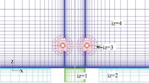
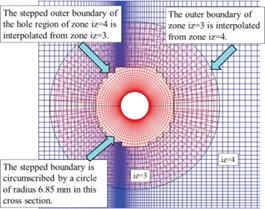
Figure 4 shows the cross-section of the structured mesh used for the computation. The mesh was three-dimensional and axisymmetric. Every five grid lines are drawn for clarity. There were a total of approximately 5.2M grid points. The overall mesh consisted of four zones: the inlet nozzle, the exterior domain of the nozzle, the ring zone, and the background zone. Each zone is shown in a different color. The ring in the computational domains was represented with the overset method. Figure 5 shows the interpolation locations. The outer boundaries of the ring zone (iz=3) were interpolated from the background zone (iz=4) at each time step. The boundaries of the blank region of the background space were interpolated from the ring zone. Trilinear interpolation was used in this study. The z-axis was defined in the streamwise (axial) direction. Near the walls, the first mesh widths in the normal directions were 8.33×10⁻⁴d0. The streamwise widths of the background mesh around the ring were approximately 3.28×10²d0. The far boundaries in the streamwise (z) and radial (r) directions were located at 70.36d0 and 70.86d0, respectively. Figure 6 shows the distribution of the mesh widths in the z and r directions near the nozzle exit for the present mesh.
Figure 4. Computational mesh for the ring tone. The mesh is three-dimensional and axisymmetric. Only the cross-sections in the x-z plane are shown. Zones iz = 1,…,4 are the nozzle inlet, the exterior domain of the nozzle, the ring zone, and the background zone, respectively. Every five grid lines are drawn for clarity
Figure 5. Interpolation between iz=3 and 4 on a cross-section
Figure 6. Distribution of the mesh width for the baseline (present) and refined mesh (fine) for r/d0, z/d0=1–3
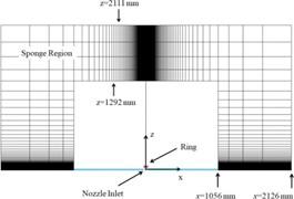
A refined mesh of approximately 7.9M grid points was used for the mesh resolution study, which will be discussed later in Sec. 5, and the mesh width is also shown in the figure. The same sponge layer method as in [10] was used to prevent spurious pressure wave reflection from the far boundaries. Figure 7 shows the sponge regions. The inlet boundary of the inlet nozzle was located at z=-0.6d0. At the inlet, a Pohlhausen-type laminar velocity profile is imposed. The boundary layer thickness is 2mm. This value is consistent with the hot-wire measurements.
t denotes the elapsed time from the initial condition, and td is the time corresponding to 4000 computational time steps. t=0 corresponds to the initial condition with quiescent air in the flow field except for the nozzle inlet, where the velocity profile was imposed. Velocities and lengths are non-dimensionalized with reference quantities vref and lref, respectively. In this study, vref=340 m/s and lref =1mm. A computational time step with dimension is 120´10-4(lref/vref).
Figure 7. Sponge regions (axisymmetric)
Vortex motion and interaction with a ring play a vital role in this study. In order to scrutinize vortex motion, a novel clustering method of vortical points applicable to the cylindrical coordinate system is developed extending clustering algorithms proposed previously by one of the authors [12-15].
The proposed method consists of two steps. The first step is to extract mesh points that have strong swirl around them as a point cloud. This is achieved by the λci criterion [19], i.e., when the velocity gradient tensor has one real eigenvalue and two complex conjugate eigenvalues, the flow swirls around the axis pointing in the direction of the eigenvector of the real eigenvalue. This criterion selects vortical points that have λci greater than some threshold λci,thresh. In this study, lci,thresh =5×10⁻³ corresponding to the 1.8% of the total mesh points in iz=4 was used taking into account the distribution of extracted vortices. The selection of extracted mesh points can be refined further by scalar-valued and/or vector-valued functions defined on the mesh points. The second step is to divide the extracted points into volume clusters on the basis of the Euclidian distance. Extracted points on the same j-plane mutually located within a distance of ε are gathered into the same planar cluster/group. In this study, ε is set as 1 mm. Considering correspondence between planar clusters on the j- and (j+1)- planes, the clusters are then grouped into the same volume cluster/group in the circumferential direction. Here, j is considered as the index of a structured mesh for the circumferential direction. The correspondence between two planar clusters on the two successive planes is judged considering the degree of rotationally projected overlap (RDPO) in the circumferential direction as follows: Two planar clusters Ci and Cαl, respectively, on the jth and (j+1)th planes are considered. Then, the RDPO between them is defined by:
$\mathrm{RDPO} \equiv \frac{\#\left(\operatorname{Prj}_\theta\left(C_i\right) \cap \operatorname{Prj}_\theta\left(C_{\alpha l}\right)\right)}{\min \left(\# C_i, \# C_{\alpha l}\right)}$ (1)
Here, Prjθ(Ci) and Prjθ(Cαl), respectively, denotes the rotational projection of the elements of Ci and Cαl to the j=1 planes. If RDPO≥0.5, it is considered that Ci and Cαl have correspondence. This clustering operation is repeated within a range of the streamwise index [jmin, jmax].
The extraction of points by the λci criterion enables the extraction of the internal points of vortices, which is not included in the iso-surface representation of vortices. By this clustering method, locally connected volumetric vortical regions can be extracted. Because each cluster has a unique ID number, a particular cluster can be picked up and visualized selectively by filtering out other clusters. This remarkable property is convenient when we pay attention to a particular vortex within numerous vortices. It also becomes possible to track vortex structures in a wide range of flows, including the evaluation of correlations between vortices.
The frequency spectra of the ring tone were measured for various impingement lengths and jet velocities [20]. Similar measurements were conducted also for the hole tone to clarify the differences between the ring and hole tones.
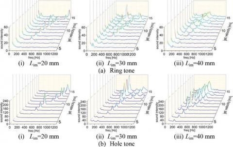
Figure 8 shows the results. As a general trend, the peak sound intensities shift to higher frequencies with increasing jet speed in both tones. Multiple series of peaks are observed for an impingement length in both tones. While the peak sound intensities generally become higher with increasing the jet speed, the amplification is not necessarily monotonic. Compared with the hole tone, the peak sound intensities for the ring tone are much lower, and the frequency distribution is broader. The lower intensity of the ring tone is consistent with [21].
Figure 8. Frequency spectra for various impingement lengths and jet speeds
Figure 9. Variation of the dominant peak frequency with the jet speed for various impingement lengths for the ring tone and hole tone
Figure 10. The sandpaper stripe attached to the inner surface of the nozzle near the exit
Figure 9 shows the variation of the dominant ring-tone and hole-tone peak frequencies with the jet speed for Lim=30 mm. In the figure, correlations based on Rossiter’s equations n/f=Lim/uc+Lim/c0 [22] are also plotted. Here, n, f, Lim, and c0 are the stage index, frequency, impingement length, and speed of sound, respectively; uc=0.6u0 is the convection velocity. As with the experimental results in Figure 8, the peak frequencies generally increase linearly. Differences between the ring tone and the hole tone appear at the locations of mode jumps, i.e., jumps in the stage index. Both integer stage indices (n) and fractional indices appear.
The results of boundary-layer tripping near the nozzle exit were compared with those of the baseline case without the tripping to confirm that the jet flow exiting the nozzle was laminar. Figure 10 shows the nozzle exit with a 2-mm wide sandpaper stripe for the tripping. The grit size of the sandpaper was #40 in the Japanese Industrial Standards (JIS). Figure 11 shows the comparison of the resultant frequency spectra. Here, the sound intensities were measured at r=90 mm. As is seen from Figure 11, the sound peaks observed in the baseline case almost disappeared in the tripped case. Therefore, the boundary layer at the nozzle exit was considered laminar in the baseline case.
Figure 12 shows comparison between the distribution of ωy and vortical points divided into different volume clusters. Here, the y direction is normal to the sheet, and ωy is the y component of vorticity. Vortices shed from the nozzle exit collide with the ring. When the vortices pass through the ring, new vortices are generated around the ring. At t/td=34, a vortex ring is convected along the circular jet and between the nozzle exit and the ring. At t/td=80, the initial vortex ring collides with the ring, and secondary vortices, i.e. the wakes of the ring, are generated. After the vortices pass through the ring, some vortices are convected rapidly, and other vortices stay around the ring for a while and are convected afterward. The extracted points successfully represent interior regions of vortices.
The transient process from the initial state to the oscillatory states was analyzed to investigate the onset of the feedback oscillation. As clarified in [9], the hole tone is governed by the axisymmetric throttling mechanism, which links mass flow through the hole, vortex impingement and global pressure fluctuation. The ring tone was analyzed from the same viewpoint. Figures 13-15 shows the time variation of the mass flow rates through the ring and gauge pressure sampled at P1[(r,z)=(15,0.126)], P2[(7.46,0.126)], and P3[(22.5,0.126)], and the time variation of circumferentially-averaged vrand vzat z=3.25-32.25 mm of r=d0/2, respectively.
The axial position of the mass flow evaluation is the center of the ring. Initially, the mass flow increases monotonically until around t/td=72. Oscillations in the mass flow appear afterwards. Peaks are observed at t/td=72, 94, and 143, and valleys are observed at t/td=83, 124, and 154. The usage of the refined mesh does not change the time history of the mass flow. Therefore, results on the present mesh are accurate enough. The peaks and valleys of the gauge pressure approximately coincide with those of the mass flow variation, which means that mass flow variation induces the pressure oscillations. The time for sound propagation over Lim=30 mm is ∆t/td=0.625. Therefore, the time lag of the pressure fluctuation between the ring and the nozzle exit is negligible.
Figure 11. Comparison between the baseline case and the tripped case
Figure 12. Distribution of ωy on y=0 plane (left) and vortical points divided into different clusters (right). Only vortical points that have swirls larger than |λci|=5×10⁻³ are plotted. Different colors show different volumetric clusters. The limitation of the number of recognizable colors means that some different volume clusters are shown in the same color
Figure 13. Time variation of mass flow rates through the ring $\dot{m}$ and gauge pressure Pg. The subscripts of the gauge pressure denote sampling locations. P1: (r,z)=(15,0.126); P2: (7.46,0.126); and P3: (22.5,0.126). Here, the mass flow rates and the gauge pressure are non-dimensionalized by ρ0u0π(d0/2)2 and ρ0u02, respectively. ρ0 is the density at the nozzle exit
Since the mass flow rate is determined by a surface integral, high-frequency fluctuations are flattened. On the other hand, pressure is sampled at a point and high-frequency fluctuations appear. The time history of pressure also shows the high-frequency fluctuations around 600 Hz that were observed in the experiment. In addition, the computation is mainly targeted at the early stage before the flow rate through the ring begins to fluctuate. On the other hand, in the experiment, the sound was measured after a long period of time since the wind tunnel had been started. Despite these differences, the fact that the 600-Hz fluctuation described above was also seen in the computation strongly supports its validity.
Figure 14. Time variation of circumferentially-averaged vr at each z coordinate of r=d0/2
Figure 15. Time variation of circumferentially-averaged vz at each z coordinate of r=d0/2
The velocity vector v at a point is decomposed into the radial (r), axial (z), and circumferential (θ) components using cylindrical coordinates: $v=v_r \boldsymbol{e}_r+v_\theta \boldsymbol{e}_\theta+v_z \boldsymbol{e}_z$, where er, eθ and ez are the unit normal basis vectors. The downstream direction of the rotational axis is taken as the positive z direction, and ez and er are taken in the positive z direction and outward directions, respectively. The circumferential direction is then defined according to the right-handed system. At the peaks, vz and vr are generally higher than at the valleys. Positive vr means that flow vectors point outward when the flow passes through the ring, and negative vr means that flow vectors point inward. Thus, the periodic variation of flow vectors causes mass flow variation through the ring. As found in Figures 14 and 15, vr and vz vary periodically in the downstream direction around the edge of the circular jet.
Volume clusters in Figure 16 facilitate understanding vortex locations and the distribution of vortices leading to the distributions of the above vr and vz. As observed in Figure 16a, the bulged regions denoted by the black arrows leave the ring when the mass flows become peaks. When the mass flows become valleys, the bulged regions collide with the ring as found in Figure 16b. Volume clusters corresponding to these regions are also confirmed.
Figure 17 shows the distributions of Pg/p∞ when the mass flows through the rings are peaks and valleys. Although the pressure becomes high in the regions around the jet connecting the nozzle exit and the ring at the peaks, it becomes low at the valleys. Jet fluid is pushed and mass flow through the ring becomes large when the ambient pressure is high, and jet fluid is pulled back (decelerated) and mass flow through the ring becomes small when the ambient pressure is low. Thus, this mechanism generates a self-sustained feedback oscillation.
Figure 16. Distribution of ωy and vortical points divided into different volume clusters when mass flows through the ring are peaks and valleys. Only vortical points that have swirls larger than $\left|\lambda_{c i}\right|=5 \times 10^{-3}$ are plotted. Different colors show different volume clusters. The limitation of the number of recognizable colors means that some different volume clusters are shown in the same color
Figure 17. Distribution of Pg/p∞ when mass flows through the ring are peaks and valleys
The ring tone was investigated via experiments and direct sound computation. In the experiments, the frequency spectra of the ring tone were measured for various jet velocities and impingement lengths. The ring tone was also compared with the hole tone. The computation investigated the onset of the self-sustained feedback oscillation in the ring tone from the viewpoint of the throttling mechanism. To clarify vortex motion and locations clearly without being hidden in the cloud of vortices visualized by iso-surfaces, the clustering method of vortical points is developed and applied. In this method, point clouds in vortical regions are first extracted by the λci criterion. The points are then divided into each locally connected groups separated from each other on the basis of the Euclidian distance. The mass flow through the ring varies due to the variation in flow velocity and angle that originate in the interaction of a vortex ring around a sinuously deformed jet with the obstacle ring. This interaction is accompanied by flow separation and the generation of secondary vortices. The mass flow becomes large when the ambient pressure in the region extending from the nozzle exit and the ring becomes high and becomes small when the ambient pressure becomes low. Thus, the pressure fluctuation perturbs the nozzle exit where discrete vortices are generated.
Computations were partly conducted using a supercomputer system at the Japan Aerospace Exploration Agency (JAXA-JSS3). The authors thank Shin Nippon Feather Core Co., Ltd. for providing us with honeycomb meshes for the wind tunnel developed in this study. The authors thank Mr. Kazuto Takimoto, a former graduate student of Ehime University, Japan, for fruitful discussion on the ring tone. We also thank Mrs. Ko Higano and Akihiro Yamaguchi for their assistance in the experiments. The authors thank Professor Masami Nakano of Tohoku University for providing us with the hot-wire anemometer system.
[1] Rayleigh, L. (1945). Theory of Sound, Vol. 2. Dover Publication, pp. 410-412.
[2] Rockwell, D., Naudascher, E. (1979). Self-sustained oscillations of impinging free shear layers. Annual Review of Fluid Mechanics, 11: 67–94. https://doi.org/10.1146/annurev.fl.11.010179.000435
[3] Blake, W.K. (1986). Mechanics of flow-induced sound and vibration, Vol. 1, Academic Press, Inc., pp. 151.
[4] Howe, M.S. (1998). Acoustics of fluid-structure interactions, Cambridge University Press.
[5] Chanaud, R.C., Powell, A. (1965). Some experiments concerning the hole and ring tone. The Journal of the Acoustical Society of America, 37(5): 902-911. https://doi.org/10.1121/1.1909476
[6] Obata, T., Kurasawa, H., Haneda, Y. (1995). Self-excited oscillation in an axisymmetric jet with a coaxial ring. Transactions of the Japan Society of Mechanical Engineers Series B, 61(583): 106-112.
[7] Langthjem, M.A., Nakano, M. (2005). A numerical simulation of the hole-tone feedback cycle based on an axisymmetric discrete vortex method and Curle’s equation. Journal of Sound and Vibration, 288(1-2): 133-176. https://doi.org/10.1016/j.jsv.2004.12.023
[8] Langthjem, M.A., Nakano, M. (2010). A three-dimensional study of the hole-tone feedback problem. RIMS kôkyûroku, 1697: 80-94.
[9] Matsuura, K., Nakano, M. (2011). Direct computation of a hole-tone feedback system at very low Mach numbers. Journal of Fluid Science and Technology, 6(4): 548-561. https://doi.org/10.1299/jfst.6.548
[10] Matsuura, K., Nakano, M. (2012). A throttling mechanism sustaining a hole tone feedback system at very low Mach numbers. Journal of Fluid Mechanics, 710: 569-605. https://doi.org/10.1017/jfm.2012.377
[11] Matsuura, K., Mukai, K., Langthjem, M.A. (2021). Computational and experimental study on ring tone. WIT Transactions on Engineering Sciences, WIT Press.
[12] Matsuura, K. (2020). Algorithmic exploration of dominant terms around hairpin vortices generated during boundary-layer transition under free-stream turbulence. International Journal of Environmental Impacts: Management, Mitigation and Recovery, 3(1): 69-83. https://doi.org/10.2495/ei-v3-n1-69-83
[13] Matsuura, K., Fukumoto, Y. (2020). Development of a vortical clustering algorithm in a transitional boundary-layer. Proceeding of the 25th Conference of the Japan Society of Fluid Mechanics, Chushikoku & Kyushu Branch, 1.
[14] Matsuura, K. (2021). Vortical point clustering for transitional boundary-layer flows in a gas turbine cascade. Proceeding of the 3rd International Conference on Energy & Power, pp. 1-7.
[15] Matsuura, K., Fukumoto, Y. (2022). Hierarchical clustering method of volumetric vertical regions with application to the late stage of laminar-turbulent transition. Physical Review Fluids, 7: 1-46. https://doi.org/10.1103/physrevfluids.7.054703
[16] Su, Y. (1991). Flow analysis and design of three-dimensional wind tunnel contractions. AIAA Journal, 29(1): 1912-1920.
[17] Lele, S.K. (1992). Compact finite difference schemes with spectral-like resolution. Journal of Computational Physics, 103(1): 16-42 https://doi.org/10.1016/0021-9991(92)90324-r
[18] Gaitonde, D.V., Visbal, M.R. (2000). Padé-type higher-order boundary filters for the Navier-Stokes equations. AIAA Journal, 38(11): 2103-2112.
[19] Zhou, J., Adrian, R.J., Balachandar, S., Kendal, T.M. (1999). Mechanisms for generating coherent packets of hairpin vortices in channel flow. Journal of Fluid Mechanics, 387(5): 353-396. https://doi.org/10.1017/s002211209900467x
[20] Mukai, K., Matsuura, K. (2021). Experiments and computations on ring tone. Proceeding of JSME, Chushikoku, 59th General assembly meeting, Japanese. pp. 1-2.
[21] Powell, A. (1990). Some aspects of aeroacoustics: from Reyleigh until today. Journal of Vibration and Acoustics, 112: 145-159. https://doi.org/10.1115/1.2930107
[22] Rossiter, J.E. (1962). The effect of cavities on the buffeting of aircraft. Royal Aircraft Establishment Technical Memorandum, 754.