Arief Goeritno* | Irwan Nugraha | Syofyan Rasiman | Ayumi Johan
© 2020 IIETA. This article is published by IIETA and is licensed under the CC BY 4.0 license (http://creativecommons.org/licenses/by/4.0/).
OPEN ACCESS
In this paper explains the classical aspects in measure the differential relay performance. The classical aspects use the simulation through inrush current into the power transformer under three conditions. The first condition is giving the normal phenomenon as phenomenon of loading, the second condition is giving the fault phenomenon for outside of the protection zone, and the third condition is giving the fault phenomenon for inside of the protection zone. The result of measurement during loading condition, the differential relay not operate, because relay is set with value of 130% of the largest current between the three phases, so that the adjustable current is 4.45 mA. The results of current measurement to the differential relay when the fault condition is provided outside of the protection area, the current value to the differential relay should of zero mA and the differential relay not operate. The result of measurement of the current flow to the differential relay when giving the fault phenomenon inside the protection zone is obtained flow to relay at the phase-R is 127.7 mA, phase-S is 123.9 mA, and phase-T equal to 123.8 mA, while the result of calculation of the current flow to the differential relay of each phase of 152.61 mA, and the differential relay operate. After giving all of three conditions, the differential relay performance is known.
differential relay performance, injection current into the power transformer, internal fault phenomena
The large power transformer is one of the very important components in a complex electrical power system, for which various types of the protection system and the monitoring scheme have been developed over the years. A power transformer is a most expensive electrical power device and its operation directly affects the performance of the other equipment connected to it [1]. Therefore, it is necessary to use an efficient protection scheme and the monitoring system to ensure its physical integrity, as well as a long time for the operating life. The protection system for the power transformers is a critical phenomenon. Traditionally, a methods for the power transformer protection that uses its terminal behavior based on a differential protection is considered to be the very widely used technique for the performing of protection functions [1]. The protection method for the power transformer should avoid and block the differential relay tripping phenomenon during magnetizing inrush and should rapidly operate its tripping during internal faults.
A scheme of differential protection can be used to protect the primary and secondary windings of the three-phase power transformer against faults phenomena. This method is basically based on the difference between the error and other operating conditions [1]. As an essential result if choose a proper scheme of identification which can discriminate and distinguishes the magnetizing inrush and internal fault current while a new power transformer is being installed by electrical power companies. The fundamental principle of operating the differential protection for power transformer is based on comparison of the primary and secondary winding of the currents transformer. If any unbalance encountered in between primary and secondary currents, the relay will actuate and inter trip both the circuit breaker on side of primary and secondary that installed and become an integral part of the power transformer [1].
Protection system using the protection relay is a set of equipment in a particular circuit that functions as a response to a faults that occur in the electrical power system [2]. Protection relay system automatically as a driver for circuit breaker (CBs) operation, needs to adjust the protection relay [3]. The opening operation of the CBs for isolation or release of parts of the system is interrupted, so as not to impact other parts of the electrical power system without interruption, very closely related to the performance of the CBs [2, 4]. Schematic diagram of a simple circuit of a protection system with installing the protection relay is shown in Figure 1.
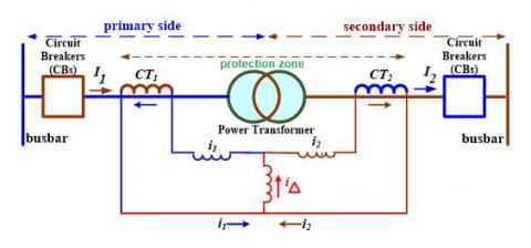
The principle of differential relay operation is based on (i) comparison of current vectors between I1 and I2 or between i1 and i2, (ii) the CT1 and CT2 must be ratios such that the value of i1= i2, and (iii) the connection of the polarity of CT1 and CT2 must be correct. Schematic diagram of differential relay placement is shown in Figure 2.
Notes: (1) the primary side of CT’s is connected in series with the protected circuit; (2) the secondary side of CT’s along with the coil of relay; (3) driver (tripping) circuit for CBs and battery
Figure 1. Schematic diagram of a simple circuit of a protection system with installing the protection relay
Figure 2. Schematic diagram of differential relay placement
Based on Figure 2, the calculation of the current detected by the differential relay per phase and the restraining currents [5-7], as discussed in Eqns. (1) and (2).
$\boldsymbol{i}_{d}=\left|\boldsymbol{i}_{1}-\boldsymbol{i}_{2}\right|=0$ (1)
$i_{r}=\frac{\left|i_{1}\right|+\left|i_{2}\right|}{2}$ (2)
The values of id, i1, i2, and ir are the form of vector quantities. Based on Eq. (1), differential relay is not activated, if the fault that occur on outside the protection zone of power transformer [8]. Related to currents detected by differential relays [9, 10] to changes in the protection of transformer power, such as the conversion in Eq. (3).
$i_{d}=\left|i_{1}+i_{2}\right|$ (3)
where, id≠0.
Based on Eq. (3), the differential relay operates, if there is a fault in the protection zone of the power transformer. The faults in the protection zone of the power transformer result in the appearance of characteristic differences between CT1 and CT2, furthermore these differences result in the onset of current imbalances.
Utilization of protection relay for anticipation of different conditions based on electric current has been implemented in electric power systems since the late 19-th century [8] and is one of the first protection systems ever used [11]. Detection of different conditions is done by comparing the current flowing in and out of the protected object [5, 6, 12, 13], in this case is the power transformer. Faults in power transformers are divided into two types, namely external and internal faults [14]. Faults originating from external, including overvoltage, overfluxing, lessfrequency, and short circuit fault outside of the transformer [15, 16]. Internal faults on power transformers are events with probabilities ranging from 70-80% [15, 16] which are distinguished by two types of faults, namely (a) initial disruption (incipient faults) and (b) short circuit interruptions occur in transformers [14, 17, 18]. Initial disruptions include i) the existence of an arc, ii) the presence of a disturbance in the cooling system, and/or iii) there is a circulating current in the transformers that are operated in parallel. The three faults included in the initial disturbance are the cause of the existence of local heating, but do not affect the overall transformer temperature [19]. These faults cannot be detected from the transformer winding connection, because the value and balance of current and voltage that occur are not much different from the condition when the power transformer is operated under normal conditions [16].
The objectives for measurement of differential relay performance are carried out through (a) simulation of loading phenomenon on the power transformer, (b) simulation of fault phenomenon on outside the protection zone, and (c) simulation of fault phenomenon on inside the protection zone of power transformer. The fault condition is chosen as three-phase short circuit fault phenomena and given an input voltage value of 380 volts (phase to phase), so that the primary current value entering the transformer is obtained. The power transformer is used as an object with selected capacity is amounting to 60 MVA and an impedance value of 12.34% or 0.1234 per unit (p.u.) that copied from the nameplate.
The relay differential used for the protection system is a unit type with a specific equipment zone. Only in the case of a fault internal to the protection zone will the difference between the input and output currents be high. However, the differential currents can sometimes be significant even though without internal faults [9]. This is due to certain characteristics of current transformers with different saturation levels or nonlinearities for measuring the input and output currents. The power transformer is protected with the exception of inrush current and over current excitation and most of the other problems, can be solved by using percent differential relay that added to the normal differential relay with two restraining coils fed by the zone-through currents [9].
Installation of the percent differential relay is carried out with (i) proper choice of the resulting percent differential characteristic and (ii) proper connection of the current transformers on both side of the power transformer. The differential protective relays with percentage restraint have been in service for many years [9, 20]. Currents of an operating and a restraining were compared by the differential elements [9]. Differential relays in a good perform for external faults, as long as the CTs is reproducing the primary current correctly. When one of the CTs on saturate condition or if both of CTs saturate with different levels, then the false operating current appears in the differential relay, so could cause relay on mal-operation [9].
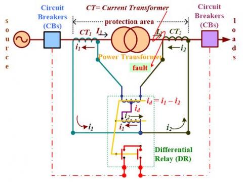
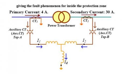
The types of faults that occur based on the protection zone, namely the faults for outside and inside of the protection zone [8]. Schematic diagram of the existence of faults on inside the protection zone against the power transformers is shown in Figure 3.
Figure 3. Schematic diagram of the existence of faults inside the protection zone against the power transformer
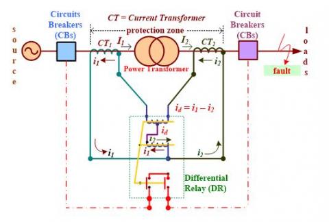
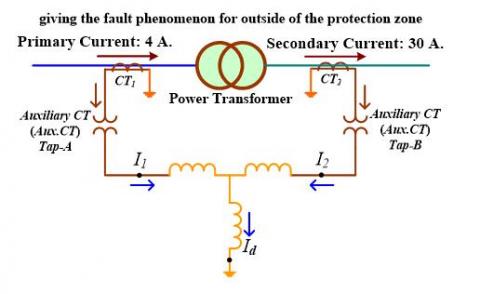
Schematic diagram of the existence of faults on outside the protection zone against the power transformer is shown in Figure 4.
Figure 4. Schematic diagram of the existence of faults on outside the protection zone against the power transformer
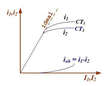
Differential relays are selective relays, so that if a fault occur on the protected object inside its protection zone, the relay operates, whereas if a fault occur outside the protection zone for protected object, the relay does not operate [8]. With regard to the selective nature, the differential relay is the main protection that does not need to be coordinated with the other types of relays. The response shown by the differential relay is very fast and no time delay is needed [13]. The relationship between input and output currents in the current transformer [8, 13] is shown in Figure 5.
Based on Figure 5 is shown, that the things that influence the existence of iub, namely (i) the characteristics of the magnetic curvature of CT1 and CT2, especially in large short-circuit currents and the secondary currents are no longer linear to the primary current due to CTs saturation; (ii) the CT1 and CT2 load; and (iii) the presence of dc components at short circuit times. The dc component accelerates CT saturation. The existence of the iub is then a percentage differential relay, which is a relay with operating characteristics following the likelihood of iub [8, 13]. Based on these characteristics, if there is an external (“through fault”) with a large current and an iub, the relay does not operate [7, 21]. Thus, the spill current must be greater than a definite percentage of the “through fault” current for relay to operate. Hence, the name percentage differential relay [5].
Operating characteristics of percentage differential relay [5] are shown in Figure 6.
Figure 5. The relationship between input and output currents in the current transformer
Figure 6. Operating characteristics of percentage differential relay
Based on Figure 6 can be explained, that the curve relationship between “through fault” and the stability ratio of the percentage differential relay is substantially better than the simple differential relay [5]. The minimum pick-up (g) is intended to anticipate a number of circumstances, namely (i) current imbalances, (ii) imbalances between Auxiliary CTs used, (iii) magnetization currents, and (iv) changes in power transformer ratios due to operation of the on load tap changer [22].
The slope of the relay is usually expressed as a percentage, thus a slope of 0.25 is expressed as 25% slope. The percentage differential relay does not have a fixed pick-up value. The relay automatically adapts its pick-up value to the “through fault” current. As the “through fault” current goes on increasing, it is in effect asking the relay to take it easy, by introducing a restraining torque proportional to the circulating current. The restraining winding is also known as the biasing winding, because bias the relay towards restraint. The slope of the characteristic is also known as percentage bias. The characteristic of the percentage differential relay superimposed on the “through fault” characteristic, and the internal fault characteristic are shown in Figure 6 [5].
The slope of the internal fault characteristic can be found based on consider an internal fault in the case of a single-end-fed system. Since CT2 will not contribute any current, i.e. I2= 0, the spill current (I1-I2) will be equal to I1. The circulating current wihich is (I1-I2)/2 will be equal to I1/2. Thus, the following currents will exist during an internal fault, i.e. spill current equal to I1 and circulating current equal to I1/2. Thus, during internal faults the spill current will be two times the circulating current, giving a slope of 2, which is expressed as 200%. The minimum internal fault current below which the scheme will not respond is seen to be If, min. int. Thus, the stability ratio is If, max. ext. divided by If, min. int. The percentage differential relay can be made more ummune to mal-operation on “through fault” by increasing the slope of the characteristic [5].
Schematic diagram of the completeness structure of the oil immersed transformer, as shown in Figure 7.
Source: Engineering360 (power by IEEE GlobalSpec.): https://cr4.globalspec.com/thread/120090/11000kV-Wires-vs-11000kV-to-220V-Transformer
Figure 7. Schematic diagram of the completeness structure of the oil immersed transformer
Based on Figure 7 can be explained, that the capacity factor or power transformer rating is not the only determinant in the choice of protection equipment. Faults in the power transformer and transformer vector groups, are also the determining factors in the choice of protection equipment.
The existence of power transformers in each substation plays a very important role, so it is said to be the heart of the link between the transmission line and the distribution network [3]. Guided by the IEC 60076-1 standard it is said, that the power transformer is a static electrical device with two or more turns with the process of electromagnetic induction, changing the voltage and alternating current system into a voltage and current system with other values which are usually of different values and at the same frequency value for the purpose of transmitting electric power [11, 23]. Power transformers have been grouped into three market segments based on power size ranges [24], namely (i) small power transformers (500 to 7,500 kVA), (ii) medium power transformers (7,500 kVA to 100 MVA), and (iii) large power transformers (greater than 100 MVA).
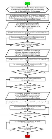
This research method is made in the form of a flow chart which is guided by the research objectives and steps for achieving that goal. Flow chart of research methods is shown in Figure 8.
Figure 8. Flow chart of research methods
Based on the flow chart of research methods in Figure 8, it can be explained, that the measurement of differential relay performance through under three conditions of giving the inrush current into the power transformer.
3.1 Simulation of loading phenomenon into the power transformer
Schematic diagram of the existence of loading phenomenon into the power transformers is shown in Figure 9.
Figure 9. Schematic diagram of the existence of loading phenomenon into the power transformers
3.2 Simulation of fault phenomenon on outside the protection zone
Schematic diagram of the existence of fault phenomenon on outside the protection zone is shown in Figure 10.
Figure 10. Schematic diagram of the existence of fault phenomenon on outside the protection zone
Using the power transformer with selected capacity is amounting to 60 MVA and an impedance value of 0.1234 p.u., then the value of the winding impedance of the power transformer in percent is converted into ohms [25] used by Eq. (4).
$X_{\text {Trans. }}=\operatorname{IoPT}(\%) \cdot Z_{\text {base}}$ (4)
To get the impedance value in Eq. (4) [25] uses the Eq. (5).
$Z_{\text {base}}=\frac{(k V)^{2}}{M V A}$ (5)
Calculation of the primary current value in the power transformer [25] uses Eq. (6).
$I_{\text {primary}}=\frac{k V}{\sqrt{3} \cdot X_{\text {trans. }}}$ (6)
The use of primary current $I_{\text {primary}}$ in Eq. (6) to determine the value of secondary current in the power transformer [5], so that the comparison equation is used as in Eq. (7).
$\alpha\left(I_{\text {secondary}}\right)=\frac{I_{\text {primary}} \cdot N_{\text {secondary}}}{N_{\text {secondary}}}$ (7)
3.3 Simulation of fault phenomenon on inside the protection zone
Schematic diagram of the existence of fault phenomenon on inside the protection zone is shown in Figure 11.
Figure 11. Schematic diagram of the existence of fault phenomenon on inside the protection zone
Computation currents as a comparison, are also used as when giving a simulation of fault conditions inside the protected zone of power transformer. Using the power transformer with selected capacity is amounting to 60 MVA, impedance value of 0.1234 p.u., then the value of the winding impedance of the power transformer in percent is converted into ohms [25] used by Eq. (4). To get the impedance value in Eq. (4) [25] uses the Eq. (5). Calculation of the primary current value in the power transformer [25] uses Eq. (6). The use of primary current $I_{\text {primary}}$ in Eq. (6) to determine the value of secondary current in the power transformer [5], so that the comparison equation is used as in Eq. (7).
Performance of the differential relay is performed through performance measurements by providing simulations of three main conditions, namely simulation of giving (a) the loading phenomenon on the power transformer, (b) the fault phenomenon on outside the protection zone, and (c) the fault phenomenon on inside the protection zone. Using the selected capacity of power transformer is amounting to 60 MVA with an impedance value of 12.34%, and setting current is determined at 130% of the largest current that occurs in each phase. First calculate the basic impedance value with Eq. (5), so that it is obtained $Z_{\text {base}}=\frac{(k V)^{2}}{M V A}=\frac{150^{2}}{60}=375$ ohm. The result is used to calculate the transformer reactance value using the Eq. (4), to obtain $X_{\text {Trans.}}=\frac{12.34}{100} \cdot 375=46.275$ ohms. Test voltage substitution of 380 volts (phase to phase), giving test currents on the primary side $I_{\text {primary}}=4 \mathrm{~A}$ and the secondary side $I_{\text {secondary}}=30 \mathrm{~A}$, then the calculated primary current is obtained by using Eq. (6) is $I_{\text {primary}}=\frac{k V}{\sqrt{3} \cdot X_{\text {Trans.}}}=\frac{380}{\sqrt{3} \cdot 46.275}=4.74$ amperes. For the acquisition of a secondary current value, a calculation is based on a comparison with Eq. (7), that is $\frac{230.9}{1732}=\frac{4.74}{\alpha}$, the value $\alpha=\frac{4.74 \cdot 1732}{230.9}=35.56$, so that the secondary current value is obtained, $I_{\text {secondary}}=35.56$ amperes.
4.1 Loading phenomenon on the power transformer
The values of current based-on the measurement in the position before Aux.CT Tap-A and Aux.CT Tap-B is the result that corresponding to the value of the ratio of CT1 and CT2. To balance the current produced by of CT1 and CT2, then Aux.CT Tap-A and Aux.CT Tap-B are needed. The values of currents based on results of measurement by providing a simulation in the form of the loading phenomenon on the power transformer is shown in Table 1.
Table 1. The values of current based on the results of measurement by providing a simulation in the form of the loading phenomenon on the power transformer
|
Side of 150 kV |
|
|
Current before Aux.CT Tap-A |
Current after Aux.CT Tap-A |
|
IR= 165.2 mA |
IR =195.6 mA |
|
IS= 165.2 mA |
IS =199.2 mA |
|
IT =199mA |
IT =188.2 mA |
|
Side of 20 kV |
|
|
Current before Aux.CT Tap-B |
Current after Aux.CT Tap-B |
|
IR= 198 mA |
IR = 198.2 mA |
|
IS= 190.4 mA |
IS= 202 mA |
|
IT = 193.3 mA |
IT = 191.7 mA |
|
Inrush current to differential relay: Phase-R= 2.6 mA; Phase-S = 2.8 mA; Phase-T= 3.5 mA. |
|
|
Setting current: 3.5 + (30% $\cdot$ 3.5) = 4.45 mA |
|
Based on Table 1 is shown, that the values of current based on the results of measurement is under the owner authority.
The setting current for the differential relay is based on the largest measurement value of each current per measured phase, so that the setting current (Iset) is obtained of 3.5 + (30% $\cdot$3.5) = 4.45 mA. When the loading phenomenon of the current entering the differential relay is mutually reduced, because the direction of the current vector produced in the simulation is opposite. The value of the setting current does not affect the operation of the differential relay, because the value of the current entering the differential relay is no more than the setting current of 130% of the largest measured current in each phase.
4.2 Fault phenomenon on outside the protection zone
The measurement of differential relay performance by granting fault phenomenon on outside the protection zone, is the measurement of performance by simulating no fault occur within the differential relay. The results of current measurement before Aux.CT, is the current generated from the ratio of CT1 and CT2. The current produced by CT needs to be balanced, so Aux.CT is needed. Based on Aux.CT, the value of the current entering the differential relay becomes balanced. The values of current based on the results of measurement by providing a simulation in the form of the fault phenomenon on outside the protection zone is shown in Table 2.
Based on Table 2 is shown, that the current value of the measurement results is under the authority. The measurement results are different from the results of calculations, because the measuring instruments used with certain sensitivity, resulting in different values. The provision of disturbance conditions outside the protected area results in the value of the current entering the relay being mutually reduced, because the direction of the current vector produced in this simulation is opposite, so the resulting reduction is zero. The reality of the results from measurements in the field is not equal to zero, so there is a tolerance value of the measuring instrument. There is a percentage error in the measurement results ranging from 2.782324% to 3.618421%.
Table 2. The values of current based on the results of measurement by providing a simulation in the form of the fault phenomenon on outside the protection zone
|
Side of 150 kV |
|
|
Current before Aux.CT Tap-A |
Current after Aux.CT Tap-A |
|
IR= 53.4 mA |
IR = 64.8 mA |
|
IS= 52.5 mA |
IS= 61.1 mA |
|
IT =56.6 mA |
IT = 60.8 mA |
|
Side of 20 kV |
|
|
Current before Aux.CT Tap-B |
Current after Aux.CT Tap-B |
|
IR= 59.3 mA |
IR= 62.9 mA |
|
IS= 56.7 mA |
IS= 62.8 mA |
|
IT = 59.3 mA |
IT = 63.0 mA |
|
Used Eq. (1), inrush current to differential relay: Phase-R: difference =|64.8-62.9|= 1.9 mA, there is a percentage error: 3.020668% Phase-S: difference =|61.1-62.8|= 1.7 mA, there is a percentage error: 2.782324% Phase-T: difference =|61.1-63.0|= 2.2 mA, there is a percentage error: 3.618421% |
|
|
Percentage error is ranging of 2.782324% to 3.618421% |
|
The calculation process is explained in the following description by using Eq. (6), namely:
a) The output current from before entering Aux.CT Tap-A on the 150 kV side is $\frac{4}{\alpha}=\frac{300}{5}$, then $\alpha=\frac{4 \cdot 5}{300}=0.066$, in order to obtain a current value of 66 mA;
b) The output current from after exiting Aux.CT Tap-A on the 150 kV side is CT1, in the presence of the Aux.CT Tap-A output in the form of a delta relationship, then multiplied by $\sqrt{3}$, so that a current value of around $\alpha=\frac{66 \cdot 29}{43} \cdot \sqrt{3}=77.09$ mA is obtained;
c) The output current from CT2 before entering Aux.CT Tap-B on the 20 kV side is $\frac{66}{\alpha}=\frac{43}{29}$, then = 0.075, in order to obtain a current value of = 75 mA; and
d) The output current from after exiting Aux.CT Tap-B on the 20 kV side is $\frac{75}{\alpha}=\frac{43}{25}$, in the presence of the Aux.CT Tap-B output in the form of a delta relationship, it is multiplied by $\sqrt{3}$, so that a current rating of $\alpha=\frac{75 \cdot 25}{43} \cdot \sqrt{3}=75.52$ mA is obtained.
The values of current based on the results of calculation by providing a simulation in the form of the fault phenomenon on outside the protection zone is shown in Table 3.
Based on Table 3 is shown, the inrush current to the differential relay calculation results in the provision of fault conditions outside the protected area is calculated by Eq. (1), obtained |77.09-75.52|= 1.57 mA.
Results of the measurements of current that inrush to the differential relay when providing fault phenomenon on outside of the protection zone is should be zero, but the measurement results are obtained (i) 1.9 mA at phase-R, there is a difference in the measurement results of 3.020668%; (ii) 1.7 mA at phase-S, there is a difference in the measurement results of 2.782324%; and (iii) 2.2 mA at phase-T, there is a difference in the measurement results of 3.618421%. Results of the calculation of current inrush to the differential relay should be zero, but the calculation results are obtained of each phase are 1.57 mA, so that each phase there is a difference of 2.078919%.
Table 3. The values of current based on the results of calculation by providing a simulation in the form of the fault phenomenon on outside the protection zone
|
Side of 150 kV |
|
|
Current before Aux.CT Tap-A |
Current after Aux.CT Tap-A |
|
IR= 66 mA |
IR= 77.09 mA |
|
IS= 66 mA |
IS= 77.09 mA |
|
IT =66 mA |
IT = 77.09 mA |
|
Side of 20 kV |
|
|
Current before Aux.CT Tap-B |
Current after Aux.CT Tap-B |
|
IR= 75 mA |
IR= 75.52 mA |
|
IS= 75 mA |
IS= 75.52 mA |
|
IT = 75 mA |
IT = 75.52 mA |
|
Inrush current to differential relay: Phase-R= 1.57 mA; Phase-S = 1.57 mA; Phase-T= 1.57 mA. |
|
|
Percentage error: 2,078919% |
|
4.3 Fault phenomenon on inside the protection zone
The value of measurement current before Aux.CT Tap-A and AuxCT Tap-B, are currents generated from ratios on CT1 and CT2. The currents generated from CT1 and CT2 need to be balanced, so Aux.CT Tap-A and Aux.CT Tap-B are needed. Based on Aux.CT Tap-A and Aux.CT Tap-B, the value of the current entering the differential relay becomes balanced. The values of current based on the results of measurement by providing a simulation in the form of the fault phenomenon on inside the protection zone is shown in Table 4.
Table 4. The values of current based on the results of measurement by providing a simulation in the form of the fault phenomenon on inside the protection zone
|
Side of 150 kV |
|
|
Current before Aux.CT Tap-A |
Current after Aux.CT Tap-A |
|
IR= 53.4 mA |
IR= 64.8 mA |
|
IS=52.5 mA |
IS= 61.1 mA |
|
IT = 6.6 mA |
IT = 60.8 mA |
|
Side of 20 kV |
|
|
Current before Aux.CT Tap-B |
Current after Aux.CT Tap-B |
|
IR= 59.3 mA |
IR= 62.9 mA |
|
IS=56.7 mA |
IS= 62.8 mA |
|
IT = 59.3 mA |
IT = 63.0 mA |
|
Used Eq. (3), inrush current to differential relay: Phase-R= |64.8+62.9| = 127.7 mA; Phase-S =|61.1+62.8|= 123.9 mA; Phase-T= |60.8+63.0|= 123.8 mA. |
|
|
Percentage error: 2,078919% |
|
Based on Table 4 is shown, that the current value of the measurement results is under the authority. The measurement results are different from the results of calculations, because the measuring instruments used with certain sensitivity, resulting in different values. Giving the fault condition inside the protection zone, the resulting value of the current entering the relay is a sum, because the direction of the current vector produced in this simulation is unidirectional, so the sum of inrush current obtained is not equal to zero. That impacts on differential relays that can operate.
The calculation process is explained in the following description by using Eqns. (6) and (7). Sequence of calculation phases as in the simulation of giving the fault condition for outside the protected zone of power transformer, so the results of the calculation are as shown in Table 2. Based on Table 3, inrush current to differential relay is calculated by Eq. (3), obtained at |77.09+75.52|= 152.61 mA.
Results of the measurements of current that inrush to the differential relay when providing fault phenomenon on inside the protected zone is the sum of inrush current not equal to zero and obtained are 127.7 mA at phase-R, 123.9 mA at phase-S, 123.8 mA at phase-T, while the results of the calculation of the inrush current to the differential relay of each phase of 152.61 mA. The value should not be equal to zero, so it is according to the condition, that the differential relay operates because the value of the inrush current to the differential relay is not equal to zero and is greater than the setting current value.
Based on the results and discussions, conclusions can be drawn according to the research objectives. In the loading phenomenon of the current entering the differential relay is mutually reduced, because the direction of the current vector produced in the simulation is opposite. The value of the setting current does not affect the operation of the differential relay, because the value of the current entering the differential relay is no more than the setting current of 130% of the largest measured current in each phase.
When providing fault phenomenon on outside of the protection zone is should be zero, but the measurement results are obtained (i) 1.9 mA at phase-R, there is a difference in the measurement results of 3.020668%; (ii) 1.7 mA at phase-S, there is a difference in the measurement results of 2.782324%; and (iii) 2.2 mA at phase-T, there is a difference in the measurement results of 3.618421%. Results of the calculation of current inrush to the differential relay should be zero, but the calculation results are obtained of each phase are 1.57 mA, so that each phase there is a difference of 2.078919%.
When providing fault phenomenon on inside the protected zone is the sum of inrush current not equal to zero and obtained are 127.7 mA at phase-R, 123.9 mA at phase-S, 123.8 mA at phase-T, while the results of the calculation of the inrush current to the differential relay of each phase of 152.61 mA. The value should not be equal to zero, so it is according to the condition, that the differential relay operates because the value of the inrush current to the differential relay is not equal to zero and is greater than the setting current value.
To complete the conclusion, recommendations for future work which related to the measurement of differential relay performance in power transformers can be added. This research methods can be implemented for various capacity values, voltage systems, and the impedance values of the power transformer.
|
CT1 |
current transformer that installed on the primary side of power transformer |
|
CT2 |
current transformer that installed on the secondary side of power transformer |
|
I1 |
current originating to the CT1 input |
|
I2 |
current originating to the CT2 input |
|
i1 |
current originating from the CT1 output that detected by the differential relay |
|
i2 |
current originating from the CT2 output that detected by the differential relay |
|
id |
the value of current that detected by the differential relay |
|
ir |
The value of curb current |
|
iub |
the difference between the currents comes from the CT1 output and from the CT2 output that the differential relay is detected |
|
XTrans |
the value of impedance on the power transformer, [ohm]; |
|
IoPT(%) |
the value of impedance on winding in the power transformer in percent; |
|
Zbase |
the basic impedance of all components in the system, [ohms]. |
|
kV |
kilo Volt, unit of the voltage value |
|
MVA |
Mega Volt Ampere, unit of the apparent power |
|
Iprimary |
the value of current on the primary side of power transformer |
|
Isecondary |
the value of current on the secondary side of power transformer |
|
α(Isecondary) |
Ratio as a function of the value of secondary current on the power transformer |
|
Nsecondary |
a number of the secondary windings on the power transformer |
|
Greek symbols |
|
|
α |
ratio for the value of current on the power transformer |
[1] Kainth, H.S., Sharma, G. (2014). A new method for differential protection in power transformer. IOSR Journal of Electrical and Electronics Engineering (IOSR-JEEE), 8(2): 64-70. https://doi.org/10.9790/1676-09246470
[2] Blackburn, J.L., Domin, T.J. (2006). Protective Relaying: Principles and Applications, Third Edition. CRC Press, Boca Raton, 1-36.
[3] Goeritno, A., Saidah. (2014). Simulation of single-phase to ground fault to anticipate against the sympathetic tripping phenomena. The 1st International Conference on Engineering, Technology and Industrial Application (the 1st ICETIA, 2014), Surakarta, Indonesia, pp. 229-233.
[4] Goeritno, A., Rasiman, S. (2017). Performance of bulk oil circuit breaker (BOCB) influenced by its parameters (case study at the substation of Bogor Baru). The 3rd International Conference on Engineering, Technology and Industrial Application (the 3rd ICETIA, 2016), pp. 1-12. https://doi.org/10.1063/1.4985446
[5] Paithankar, Y.G., Bhide, S.R. (2003). Fundamentals of Power System Protection. Printice-Hall of India, Private Limited, New Delhi, 57-73.
[6] Horowitz, S.H., Phadke, A.G. (2008). Power System Relaying. John Wiley & Sons Ltd, Chichester, 195-224.
[7] Turner, S. (2011). Testing numerical transformer differential relays. The 64th Annual Conference for Protective Relay Engineers, College Station, Texas, USA, pp. 251-256.
[8] Zigler, G. (2012). Numerical Differential Protection: Principles and Applications, Second Edition. Publicis, Erlangen, 17-50.
[9] Behrendt, K., Fischer, N., Labuschagne, C. (2006). Considerations for using harmonic blocking and harmonic restraint techniques on transformer differential relays. The 33rd Annual Western Protective Relay Conference, Spokane, Washington, pp. 1-17.
[10] Hartmann. W. (2015). Improving pulp and paper plant MV transformer protection. 2015 61st IEEE Pulp and Paper Industry Conference (PPIC), Milwaukee, WI, USA. https://doi.org/10.1109/PPIC.2015.7165856
[11] Gajic, Z. (2008). Differential protection for arbitrary three-phase power transformers. 2008 IET 9th International Conference on Developments in Power System Protection (DPSP 2008), Glasgow, UK. https://doi.org/10.1049/cp:20080009
[12] Oza, B.A., Nair, N.K.C., Mehta, R.P., Makwana, V.H. (2010). Power System Protection and Switchgear. Tata McGraw-Hill Education Private Limited, New Delhi, 16-50.
[13] Rockefeller, G. (2013). Transformer Protection Application Guide. Basler Electric, Highland, 1-30.
[14] IEEE Std C37.91-2000 (Revision of IEEE Std C37.91-1985). (2000). IEEE Guide for Protective Relay Applications to Power Transformers, pp. 1-85. https://dx.doi,org/10.1109/IEEESTD.2000.91943
[15] Mohammadpour, H., Dashti, R. (2011). A new method presentation for fault location in power transformers. world academy of science, engineering and technology. International Journal of Electrical and Computer Engineering, 5(6): 741-746. https://doi.org/10.5281/zenodo.1084406
[16] Joshi, N.C., Sood, Y.R., Jarial, R.K.,Thapliyal, R. (2012). Transformer internal winding faults diagnosis methods: A review. MIT International Journal of Electrical and Instrumentation Engineering, 2(2): 77-81.
[17] Wang, H., Butler, K.L. (2002). Modeling transformers with internal incipient faults. IEEE Transaction on Power Delivery, 17(2): 500-509. https://doi.org/10.1109/61.997926
[18] Thangavelan, M., Prabavathi, K., Ramesh, L. (2014). Review on power transformer internal fault diagnosis. Journal of Electrical Engineering, 14(3): 372-377.
[19] Mishra, V., Prakash, S., Singh, A. (2013). Detection of internal faults in transformers by negative sequence current. SAMRIDDHI: A Journal of Physics Sciences, Engineering and Technology (S-JPSET), 4(2): 61-65. https://doi.org/10.18090/samriddhi.v4i2.1508
[20] Guzmán, A., Zocholl, S., Benmouyal, G., Altuve, H.J. (2000). Performance analysis of traditional and improved transformer differential protective relays. The 36th Annual Minnesota Power Systems Conference, Saint Paul, Minnesota, pp. 1-34.
[21] Thompson, M.J. (2011). Percentage restrained differential, percentage of what? The 64th Annual Conference for Protective Relay Engineers, College Station, pp. 278-289. http://dx.doi.org/10.1109/CPRE.2011.6035629
[22] Kasztenny, B., Kulidjian, A., Campbell, B., Marzio Pozzuoli, M. (2000). Operate and restraint signals of a transformer differential relay. The 54th Annual Georgia Tech Protective Relaying Conference, Atlanta, Minnesota, pp. 1-24.
[23] IEC 60076-1:2011. Power Transformers - Part 1: General. https://webstore.iec.ch/publication/588, accessed on Jan. 30, 2020.
[24] Sim, H.J., Digby, S.H. (2004). Power Transformer. In: Harlow, J.H. (ed.) Electric Power Transformer Engineering. CRC Press, Boca Raton.
[25] Elgerd, O.I. (1971). Electric Energy Systems Theory: An Introduction, 1st ed. Tata McGraw-Hill, New Delhi, 11-43.