Abdessalam El Yassini* | Mohammed Ali Jallal | Saida Ibnyaich | Abdelouhab Zeroual | Samira Chabaa
© 2020 IIETA. This article is published by IIETA and is licensed under the CC BY 4.0 license (http://creativecommons.org/licenses/by/4.0/).
OPEN ACCESS
A compact wide-band planar antenna is proposed using the metamaterial transmission line. The motivation of this study is to overcome the problem of low bandwidth while designing a miniaturized antenna. The proposed design consists of a rectangular patch and a square-shaped split-ring resonator (SSSRR) on the asymmetric ground plane. Strip lines are provided to connect the right ground plane to obtain the shunt inductances and improve the bandwidth. This antenna has a miniature physical size of 20×28×1.6 mm3 corresponding to the electrical size of 0.16λo × 0.23λo × 0.013λo, where λo is the free space wavelength at the resonant frequency 2.51 GHz. The obtained results show that this antenna has wide-band from 2.2 GHz to 12.63 GHz, which makes it a good candidate for cover various standards of WLAN (2.4/5.2/5.8 GHz), WiMAX (2.5/3.5/5.5 GHz), satellite TV (7.14 GHz), and X-band (10.19/ 12.02 GHz). The proposed antenna simulations and analyses were performed using the CST simulator.
patch antenna, wide-band, WLAN/WiMAX applications, multi-band wireless communication metamaterials
In recent years, wireless transmission systems have evolved rapidly. The most modern systems of communication have a miniature size and multi-frequency of operation; consequently, this leads to demand in designing compact, low-cost, small antennas with good impedance bandwidth and easily manufacturing. The patch antennas become common in the modern wireless applications due to some reasons like miniature size, low cost, and simple to integrate into wireless systems [1-5].
Thus, in order to design a multiband and broadband antenna that suitable the WLAN and WiMAX applications, various techniques have been proposed in the literature such as fractal antenna [6] and introducing slots on the radiating element or the fed line of the antenna [7]. The asymmetric coplanar waveguide is employed to former the antenna components because it achieves more design freedom compared with conventional coplanar waveguide and also helps to improve the bandwidth of the antenna [8].
Metamaterials (MTMs) structures have been much used in antenna design applications due to their unusual characteristics such as the negative refractive index (n<0), the direction of group velocity (vg), and phase vector (K) are reverse and zero propagation constant (β=0). Moreover, MTMs have been widely employed for improvement the antennas performance such as for obtained wide bandwidth antenna, enhancement the antenna radiation patterns, and designing the miniaturized [9-13].
As compared to the traditional half-wavelength antennas, MTM-based antennas have the ability to achieve a resonant frequency independent of its physical size, which offers the possibility for miniaturization [14].
Metamaterial (MTM) antennas are produced by introducing the composite right left- handed (CRLH) resonant or the unit cell approach. In the unit cell approach, multiple uniform cells are printed and separated with a gap and the total of unit cells as used affects the resonant frequency of the structure. The composite right left-handed metamaterial are artificial materials, which have new electromagnetic properties and the CRLH approach is able to minimize the number of components in wireless communication systems [15].
In this paper, we are interested to design a wide-band planar antenna by using the epsilon negative transmission line approach this is a better solution to improve the performance of the antenna in terms of the bandwidth, the impedance matching and obtain a miniature size. This paper is organized as follows; Section 2 presents the metamaterial theory. The geometry and design evolution of the suggested antenna are introduced in Section 3. A parametric study has been carried out in Section 4. The current distributions and radiation patterns of the proposed antenna are given in Section 5, and then the conclusion is presented in Section 6.
The transmission line theory can be used to study both right-handed and left-handed properties of the CRLH metamaterial structure, assuming a lossless TL will be examined for simplicity [16]. The equivalent circuit models of a purely right-handed (RH), left-handed (LH), and epsilon-negative (ENG) TL and CRLH lossless TL are shown in Figure 1(a) and Figure 1(b), Figure 1(c) and Figure 1(d), respectively.
Figure 1. Equivalent circuit model for, (a) RH TL, (b) LH TL, (c) ENG TL, RLH TL
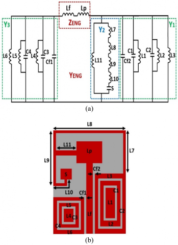
In this paper, we interested in epsilon negative transmission line ENG TL model that consist of series inductance and shunt inductance that produces a dielectric constant negative in the frequency band. The proposed antenna geometry and the equivalent circuit model are presented in Figure 2(a) and Figure 2(b) respectively. The shunt inductors L'L (L7, L8, L9, L10, L11, S) have resulted from the current flow through the split ring resonator with various lengths L'7, L'8, L'9, L'10, L'11 respectively. Series inductances L'R (Lf and Lp) are formed due to the current flow on the patch and feed line. The shunt capacitances C'R (Cf1 and Cf2) are created due to the gap between the ground and feed line. Moreover, L1, L2, L3, L4, L5, L5 are the inductances achieved on top of the asymmetric ground plane because SSSRR. The capacitances C1, C2, C3, and C4 are formed due to gaps in the SSSRR.
According to Bloch and Floquet theory, the propagation constant ($\beta_{E N G_{-} T L}(\omega)$) is calculated as follows of Epsilon Negative TL [16, 17].
$\beta_{E N G_{-} T L}(\omega)=\frac{1}{P} \cos ^{-1}\left\{1+\frac{Z_{E N G}(\omega)+Y_{E N G}(\omega)}{2}\right\}$ (1)
For the proposed antenna,
$Y_{E N G}(\omega)=\left(j \omega C_{R}^{\prime}+\frac{1}{j \omega L_{L}^{\prime}}\right)$ (2)
where, the parameters p, ZENG and YENG are representing the total length of resonator, series impedance and shunt admittance respectively. The resonance condition of the suggested antenna achieved when [18]:
$\beta_{E N G_{-} T L} p=\frac{n \pi P}{l}=\frac{n \pi}{N}$ (3)
In which n = 0, 1, 3, …., (N-1) is the number of the unit cell and l and N are the length and number of the unit cells.
Figure 2. Equivalent (a) Antenna geometry, (b) circuit
The condition β = 0 indicates zeroth-order resonance (ZOR) mode for n = 0, this resonance mode is independent of the physical size of the antenna. The antenna structure follows the open-ended boundary condition state and in this case the input impedance is calculated as follows [18]:
$Z_{i n}=-j Z_{0} \cot \beta l \stackrel{\beta \rightarrow 0}{\Longrightarrow} \frac{1}{N Y}$ (4)
where, Zin and Z0 are the input impedance and characteristic impedance line respectively. The condition β=0 indicates ZOR mode for n=0 as given in (3). The ZOR frequency of the suggested antenna is calculated as follows:
$\omega_{Z O R}=\frac{1}{\sqrt{L_{L}^{\prime} C_{R}^{\prime}}}$ (5)
The resonate frequency can be controlled through using the capacitance $C_{R}^{\prime}$ and inductance $L_{L}^{\prime}$ of the antenna.
3.1 Antenna geometry
The suggested and miniaturized multi-band CPW antenna is designed on an FR4 epoxy substrate having the thickness of 1.6 mm and the dielectric constant of εr=4.3. This antenna has the overall size of 20×28×1.6 mm3 and fed by a coplanar waveguide as shown in Figure 3(a). This structure is a combination of a rectangular square-shaped complementary concentric closed ring resonator in forme of asymmetric CPW ground plane. The right-hand ground plane is connected with the radiator rectangular and a stub by the thin strip-line. The parameters of the proposed antenna are analyzed using the CST microwave studio simulator and the dimensions of antenna are summarized in Table 1.
Figure 3(b) presents the simulated reflection coefficient S11 of the suggested antenna. For -10 dB reflection coefficient this antenna has the wide band of operating from 2.2 GHz to 12.63 GHz with eight resonant frequencies of 2.32, 3.59, 4.9, 5.80, 7.14, 8.96, 10.19, and 12.02 GHz. The proposed antenna covers the requirements of the wireless systems with multi-standard, the 2.4, 5.2, and 5.8 GHz for WLAN and 2.6, 3.5, 5.5 GHz for WiMAX, 7.14 GHz for (satellite TV) and 10.19, 12.02 for GHz (X-band).
Table 1. Dimensions of the proposed antenna
|
Parameters |
Values (mm) |
Parameters |
Values (mm) |
|
Wsub |
20 |
J2 |
1.2 |
|
Lsub |
28 |
P1 |
0.5 |
|
Wp |
9 |
P2 |
1.2 |
|
Lp |
7 |
Lg1 |
6 |
|
L1 |
13 |
Lg2 |
15 |
|
L2 |
11 |
Wf |
2.7 |
|
g |
0.4 |
Lf |
20 |
|
J1 |
0.7 |
Wg |
8 |
3.2 Antenna design
The evolution of the proposed MTMA and reflection coefficient S11 results are shown in Figure 4 and Figure 5, respectively. The proposed MTMA has been designed after three steps. Firstly, Antenna 1 in Figure 4(a) represents a conventional antenna, which composes of a rectangular patch and feed by a CPW. As shown in Figure 5, it is clear that this antenna has a bandwidth from 6 GHz to 13 GHz and a resonant frequency of 6.6 GHz. For enhancement the bandwidth, the ground plane has been designed with asymmetric form (antenna 2) for improve the capacitive part of the antenna as present in Figure 4(b). We note that the antenna 2 has two bandwidths are 3.5–6 GHz and 7.35–13 GHz. Moreover, the antenna bandwidths are poor with low impedance matching.
The thin strip inductive is archived for balancing the capacitive part as shown in Figure 4(c) (Antenna 3). It can be observed from Figure 5 that the impedance bandwidth of the antenna is ranging from 3.5 GHz to 12.63 GHz with four resonant frequencies.
Antenna 4 has been created by using one more strip line which coupling the rectangular patch with the first strip and complementary concentric closed ring resonator split (CCCRRs) on the ground plane has been added. Hence, the current distributions have to vary with more trajectory, which generates the other resonant frequencies at 2.32 GHz and at 3.59 GHz.
Figure 3. (a) The proposed antenna structure, (b) Simulated reflection coefficient S11
Figure 4. Design evolution of the proposed antenna, (a) Antenna 1, (b) Antenna 2, (c) Antenna 3, (d) Antenna 4
Figure 5. Reflection coefficient of the antenna evolution procedure
The proposed MTMA characterizes by the wide band of operating from 2.2 GHz to 12.63 GHz. a parametric study has bend used for understanding the effects of the antenna parameters on the performance result.
The Lg1 parameter is changed from 13 mm to 16 mm and the Figure 6(a) display the variation of S11 parameter with the respected values of Lg1 and keeping all other dimensions unchangeable. The variation of Lg1 has a good effect on controlling the impedance matching of the bandwidth. When the parameter Lg2 has a variation from 5 mm to 8 mm with a step of 1 mm, the resonate frequencies fr2, fr6, fr7, fr8 are affected as shown in Figure 6(b).
Figure 6. Reflection coefficient S11 for various values of (a) Lg1, (b) Lg2
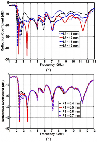
Figure 7. Reflection coefficient S11 for various values of (a) Lf, (b) P1
The parameter Lf is the length of the fed line and it is significant to study its effect on the bandwidth and the resonant frequencies as it drives the series inductance. When the Lf increases, the series inductance increases consequently the impedance matching of the antenna can be improved and contorted using the Lf. This effect can be noticed in Figure 7(a). It is observed that the antenna has a good bandwidth when Lf = 17 mm. The optimal value of the Lf is found to be 17 mm for which proposed antenna covers a bandwidth of extremely wide frequency ranging from 2.2 GHz to 12.63 GHz.
In addition, Figure 7(b) shows the variation of the reflection coefficient S11 with a change in the width of shunt inductance (P1). it can be seen that the S11 of the antenna is affected by the resonant frequencies fr2 and fr5 by the shunt inductance of the stripline.
5.1 Current distributions results
In order to understand and analyze the different resonant frequencies of the proposed antenna. The current distribution of operating frequencies is presented in this section as given in Figure 8 and Figure 9.
Figure 8. Simulated surface current distributions of the proposed MTMA at (a) 2.32 GHz, (b) 3.59 GHz and (c) 4.9 GHz
The contribution of the thin stripline in which coupling paths and the right ground plane is the effect on the resonant frequencies. As can be observed from the surface current distribution, the high current intensity is concentrated on stripline. Furthermore, strip lines occupy the large area consequently extending the electrical length of the suggested structure and give the ability for miniaturization.
In addition, high current strength can be observed on complementary concentric closed ring resonator split (CCCRRs) of the ground plane, the gap between the fed line and left-right ground planes.
Figure 9. Simulated surface current distributions of the proposed MTMA at (a) 5.8 GHz, (b) 7.14 GHz, (c) 8.96 GHz, (d) 10.19 and (e) 12.02 GHz.
5.2 Radiation patterns
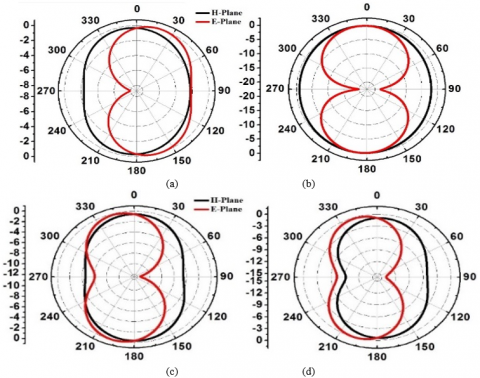
Figure 10 and Figure 11 demonstrate the obtained 2D radiation patterns of the proposed MTMA at different resonant frequencies in H-plane and E-plane. This antenna has asymmetric radiation patterns due to its asymmetric structure.
Table 2 compares the proposed antenna performance with the reference work in literature.
Figure 10. 2D radiation patterns at resonant frequencies, (a) 2.32 GHz, (b) 3.59 GHz, (c) 4.9 GHz and (c) 5.8 GHz
Figure 11. 2D radiation patterns at resonant frequencies, (a) 7.14 GHz, (b) 8.96 GHz, (c) 10.19 GHz, (d) 12.02 GHz
Table 2. Comparison of the proposed antenna with other work
|
Antenna |
Resonant Frequencies (GHz) |
Impedance Bandwidth, (%) |
Dimension (mm3) |
|
[19] |
1.81 3.10 5.81 |
3.31 49.03 2.06 |
35×38×1 |
|
[20] |
2.08 4.31 5.50 |
5.76 0.46 2 |
45×40×1.6 |
|
[17] |
1.16 2.32 3.58 |
8.54 10.25 35.75 |
30×30 ×1.6 |
|
Proposed Antenna |
2.1, 3.59, 4.9, 5.8, 7.14, 8.96, 10.19, 12.02 |
90 |
20×28×1.6 |
In this paper, a compact wideband MTM inspired antenna with a coplanar waveguide feed has been proposed and their equivalent circuit model. The antenna is designed based on ENG-TL, so that the bandwidth characteristic is studied as per the ENG-TL approach. The CCCRRs are specially used for improving the impedance matching. In addition, the proposed MTM antenna has a compact size (0.16λo × 0.23λo × 0.013λo) with a simple structure, and covers a bandwidth of extremely wide frequency ranging from 2.2 GHz to 12.63 GHz which suitable for WLAN, WiMAX, Satellite TV, and X-band. The obtained results make this antenna acceptable for wide-band application.
[1] Pandeeswari, R. (2017). A compact non-bianisotropic complementary split ring resonator inspired microstrip triple band antenna. Progress In Electromagnetics Research, 81: 115-124. https://doi.org/10.2528/PIERC17103009
[2] Augustin, G., Bybi, P.C., Sarin, V. P., Mohanan, P., Aanandan, C.K., Vasudevan, K. (2008). A compact dual-band planar antenna for DCS-1900/PCS/PHS WCDMA/IMT-2000 and WLAN applications. IEEE Antennas Wirel. Propag. Lett, 7: 108-111. https://doi.org/10.1109/LAWP.2008.919601
[3] Hu, W., Yin, Y.Z., Fei, P., Yang, X. (2011). Compact triband square-slot antenna with symmetrical L-strips for WLAN/WiMAX applications. IEEE Antennas Wirel. Propag. Lett, 10: 462-465. https://doi.org/10.1109/LAWP.2011.2154372
[4] Pei, J., Wang, A.G., Gao, S., Leng, W. (2011). Miniaturized triple-band antenna with a defected ground plane for WLAN / WiMAX applications. IEEE Antennas and Wireless Propagation Letters, 10: 298-301. https://doi.org/10.1109/LAWP.2011.2140090
[5] Ali, T., Biradar, R.C. (2018). A triple‐band highly miniaturized antenna for WiMAX/WLAN applications. Microwave Optical Technology Letters, 60(2): 466-471. https://doi.org/10.1002/mop.30993
[6] Beigi, P., Mohammadi, P. (2016). A novel small triple-band monopole antenna with crinkle fractal structure. AEU-International Journal of Electronics and Communications, 70(10): 1382-1387. https://doi.org/10.1016/j.aeue.2016.07.013
[7] El Yassini, A., Ibnyaich, S., Chabaa, S., Zeroual, A. (2020), Miniaturized broadbandmultiband planar antenna with a symmetric quartercircular ground plane for WLAN/WiMAX standards. Microwave Optical Technology Letters, 13: 1-12. https://doi.org/10.1002/mop.32402
[8] Shanmuganantham, T., Balamanikandan, K., Raghavan, S. (2008). CPW-fed slot antenna for wideband applications. Antennas and Propagation, 2008: 1-4. https://doi.org/10.1155/2008/379247
[9] Iyer, A.K., Eleftheriades, G.V. (2002). Negative Refractive Index Metamaterials Supporting 2-D Waves. 2002 IEEE MTT-S International Microwave Symposium Digest (Cat. No.02CH37278), Seattle, WA, USA. https://doi.org/10.1109/MWSYM.2002.1011823
[10] Cheng, Z., Guang-ming, W., Jian-gang, L. (2011). Novel zeroth-order resonator antenna based on composite right/left handed (CRLH) transmission line. Proceedings of 2011 Cross Strait Quad-Regional Radio Science and Wireless Technology Conference, Harbin, China. https://doi.org/10.1109/CSQRWC.2011.6036963
[11] Majedi, M.S., Attari, A.R. (2013). Dual-band resonance antennas using epsilon negative transmission line. IET Microwaves, Antennas Propag, 7(4): 259-267. https://doi.org/10.1049/iet-map.2012.0542
[12] Park, J.H., Ryu, Y.H., Lee, J.G., Lee, J.H. (2007). Epsilon negative zeroth-order resonator antenna. IEEE Trans. Antennas Propag, 55(12): 3710-3712. https://doi.org/10.1109/TAP.2007.910505
[13] Salih, A.A., Sharawi, M.S. (2016). A dual-band highly miniaturized patch antenna. IEEE Antennas Wirel. Propag. Lett, 15: 1783-1786. https://doi.org/10.1109/LAWP.2016.2536678
[14] Dong, Y., Itoh, T. (2010). Miniaturized substrate integrated waveguide slot antennas based on negative order resonance. IEEE Trans. Antennas Propag, 58(12): 3856-3864. https://doi.org/10.1109/TAP.2010.2078449
[15] Lai, A., Itoh, T., Caloz, C. (2004). Composite right/left-handed transmision line metamaterials. IEEE Microw. Mag, 5(3) 34-50. https://doi.org/10.1109/MMW.2004.1337766
[16] Sharma, S.K., Gupta, A., Chaudhary, R.K. (2015). Epsilon negative cpw-fed zeroth-order resonating antenna with backed ground plane for extended bandwidth and miniaturization. IEEE Trans. Antennas Propag, 63(11): 5197-5203. https://doi.org/10.1109/TAP.2015.2477521
[17] Kumar, R., Singh, R., Chaudhary, R.K. (2018). Miniaturised triple-band antenna loaded with complementary concentric closed ring resonators with asymmetric coplanar waveguide-fed based on epsilon negative transmission line. IET Microwaves, Antennas Propag, 12(13): 2073-2079. https://doi.org/10.1049/iet-map.2018.5164
[18] Park, J., Ryu, Y., Lee, J.G. (2007). Epsilon negative zeroth order resonating antenna. IEEE Trans. Antennas Propag, 55(12): 3710-3712. https://doi.org/10.1109/TAP.2007.910505
[19] Zhu, C., Li, T., Li, K., Su, Z.J., Wang, X., Zhai, H.Q., Li, L., Liang, C.H. (2015). Electrically small metamaterial-inspired tri-band antenna with meta-mode. IEEE Antennas Wirel. Propag. Lett, 14: 1738-1741. https://doi.org/10.1109/LAWP.2015.2421356
[20] Gupta, A., Chaudhary, R.K. (2016). A compact planar metamaterial triple-band antenna with complementary closed-ring resonator. Wirel. Pers. Commun, 88: 203-210. https://doi.org/10.1007/s11277-015-3087-6