Yanghua Gao* | Weidong Lou | Hailiang Lu
© 2020 IIETA. This article is published by IIETA and is licensed under the CC BY 4.0 license (http://creativecommons.org/licenses/by/4.0/).
OPEN ACCESS
This paper presents an ultra-wideband antenna formed with lumped elements series loading and parallel loading for indoor applications. Loaded with parallel and series resistors, the surface current of the antenna is distributed in the form of traveling wave, thereby effectively widening the impedance bandwidth of the antenna. The proposed antenna can operate over the whole band from 0.1 G to 3 GHz and maintains high efficiency throughout its whole frequency band. Moreover, the antenna has a compact structure of 310×270×0.8 mm3. Over the entire frequency range, it can obtain good omnidirectional radiation performance, gain and radiation efficiency. This paper presents and discusses the antenna design and experimental results in detail. With the ultra-wideband property, the proposed antenna has the potential to be applied in electromagnetic field measurement, radio monitoring and visualization instruments.
loaded antenna, resistively loaded, indoor antenna, ultra-wideband (UWB)
In modem communication, especially in radio instrument/monitoring applications, the wideband antenna has always been an important research topic. There are several technologies applicable for the implementation of wideband antennas, and a most popular one is impedance loading, which can maximize the bandwidth of an antenna, but with a low efficiency. In recent years, a lot of work has been done [1-3]. With a suitable loading profile chosen, the traveling wave current distribution will be produced on the antenna, so that the electrical characteristics, including the input resistance and the far field pattern, will have the wideband property [4-8]. The suitable loading profile is the result of a trade-off between the bandwidth and the efficiency. A non-reflecting resistively loaded antenna can bring quite a wide bandwidth, but with an efficiency of no more than 50% [9-13].
Late-time ringing is caused mainly by multiple reflections between the open ends and feed point of the antenna, which indicates the narrowband nature of the antenna. The most widely used technique for increasing the antenna bandwidth (thus reducing late-time ringing) is resistive loading, in which the well-known Wu–King profile can be used to determine the loading distribution along the antenna. The main disadvantage of resistive loading is that it considerably reduces the radiation efficiency. In the case of the Wu–King profile, the radiation efficiency is shown to decrease to as low as 23%. To avoid this drawback, the use of non-dissipative reactive loading has been proposed. Nyquist and Chen suggested introducing a pair of lumped reactive elements and placing the elements at the respective optimal distance from the antenna ends to increase the antenna bandwidth by a certain frequency spectrum. Several investigators have proposed improved methods using distributed capacitive loading with different loading profiles. In addition, a combination of resistive and capacitive loading and empirically determined profiles have also been introduced. It has been verified that capacitive loading keeps the radiation efficiency at 100%, that a combination of resistive and capacitive loading maintains the radiation efficiency between 40% and 60% (depending on the profile), and that resistive loading can in some cases reduce the radiation efficiency down to 30% [14-18]. However, research shows that resistive loading is the most effective one for suppressing late-time ringing, while capacitive loading (alone or in combination with resistive loading) still exhibits a relatively high level of ringing [19-23]. Furthermore, difficulties have also been shown in the practical implementation of nonlinear loading profiles (e.g., Wu–King) on planar structures such as bow-tie antennas.
Now with the increasing demand for indoor communication quality, technologies that use only outdoor base stations no longer meet indoor communication needs since electromagnetic signals are highly attenuated by building walls. Therefore, the indoor antenna distribution system is developing rapidly [24-32], and the performance of indoor antennas will greatly affect the performance of the whole communication system [33-45].
Antenna design for ultra-wideband (UWB) applications is facing many challenges as it is intended to achieve an extremely broad operating frequency range. One of the challenges is to miniaturize the antennas with a broad impedance bandwidth and a high radiation efficiency. Usually, a planar design can be used to reduce the volume of a UWB antenna, where three-dimensional radiators are replaced with planar versions. For example, a UWB antenna printed onto a piece of printed circuit board (PCB) is a good option for portable devices because it can be easily embedded into wireless devices or integrated with other RF circuits. In the design of a printed UWB antenna, the radiator, the ground plane shape as well as the feeding structure can be optimized to achieve a broad impedance bandwidth. Recently, high-permittivity ceramic has been applied by the industry to further shrink the sizes of planar antennas surface-mounted onto PCBs. However, such UWB antennas often require additional impedance matching networks and/or large system ground planes. In addition, the printed UWB antenna consisting of a planar radiator and a system ground plane is essentially an unbalanced design, where the electric currents are distributed on both the radiator and the ground plane, making the radiation inevitable from the ground plane. Therefore, the performance of a printed UWB antenna is significantly affected by the shape and size of the ground plane in terms of operating frequency, impedance bandwidth and radiation patterns. Such ground-plane effects cause severe practical engineering problems such as increasing design complexity and deployment difficulty. What is more, in order to pursue faster, stable and convenient communication capabilities, a new generation of advanced mobile communication systems have been researched and put into commercial applications. However, different communication systems are incompatible with each other, and they each occupy a different frequency band - for example, 824-960MHz is for GSM900/CDMA800 systems, 1710-2170MHz for WCDMA/CDMA2000 systems, and 2570-2620 MHz/1880-1920 MHz/2300-2400MHz/2496-2690MHz for LTE Band 38/39/40/41 [46]. Therefore, an ultra-wideband (UWB) indoor antenna capable of covering multiple frequency bands at the same time is highly desirable. However, most ultra-wideband indoor antennas have three-dimensional structures and do not have low profile characteristics, making them difficult to manufacture and affecting the shape retention and decorativeness of buildings. On the other hand, patch antennas are featured with small size, light weight, low profile and easiness to manufacture, and their planar structures are also easier to be integrated with buildings, so an ultra-wideband indoor antenna with a planar structure has great advantages.
This paper presents a novel low-profile ultra-wideband indoor antenna formed by two slotted patches printed on a 0.8mm thick dielectric substrate. With parallel and series resistors loaded, the surface current of the antenna is distributed in the form of traveling wave, thereby effectively widening the impedance bandwidth of the antenna. With the inductor loaded, the radiation efficiency of the antenna is improved. The proposed antenna can cover an ultra-wide band of 0.1G-3.1GHz and has high gain in its frequency band. Moreover, the antenna has a low-profile structure of 310×270×0.8 mm3. This paper gives a simulation and studies the experimental performances of the proposed antenna.
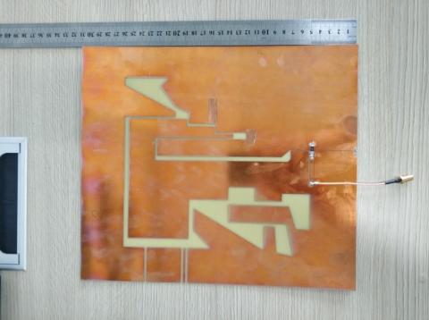
The geometry of the proposed indoor antenna with detailed dimensions is shown in Figure 1. The proposed antenna, whose overall size is 310 mm in length and 270 mm in width, is printed on a 0.8-mm-thick FR4 substrate with a relative permittivity of 4.4 and a loss tangent of 0.02. The blue section is the dielectric layer, and the yellow region is metal.
As shown in Figure 1, the proposed indoor antenna consists of two slotted metal patches, which are located on the top of the dielectric substrate. The coupling between the two metal patches is strengthened by many bends. A chip resistor soldered to the 0603 package pad is connected at the bottom of the two metal patches and used as a load resistor. With the parallel and series resistors loaded, the surface current of the antenna is distributed in the form of traveling wave, thereby effectively widening the impedance bandwidth of the antenna. The indoor antenna is fed by a 50ohm coaxial transmission line. The coaxial feeder is connected to metal patch 1 through the series resistor and the inductor, and the ground of the coaxial line is directly connected to patch 2.
(a) Antenna configuration
(b) Photograph of the antenna prototype (top view)
Figure 1. Geometry of the proposed antenna
Figure 2 plots the measured and simulated S11 of the proposed indoor antenna with the dimensions given in Figure 1. The S11 parameter was measured in an anechoic chamber with the Agilent Network Analyzer E5063A. In the low frequency band, the measured data agree with the simulated results obtained using the commercial software CST [14]. However, as the frequency increases, the parasitic effect of the lumped device is intensified, and the measured data deviate from the simulated data, and after 3 GHz, the simulated data will not be accurate. It has a wide bandwidth from 0.1GHz to 3.1GHz, enough to cover most mobile communication bands.
Figure 2. Measured and simulated S11 of the proposed antenna
Figure 3. Measured antenna gain and radiation efficiency of the proposed indoor antenna
The measured peak gain and radiation efficiency results of the proposed slot antenna are shown in Figure 3. Due to size and planar structure limitations, the antenna has a low gain and efficiency at 100MHz-600MHz. However, when the frequency is higher than 600MHz, the antenna gain rises to about 0dbi. Since the lumped device is added, the overall efficiency of the antenna is about 20%-30%. Such radiation efficiency and gain of the antenna can be accepted in practical applications.
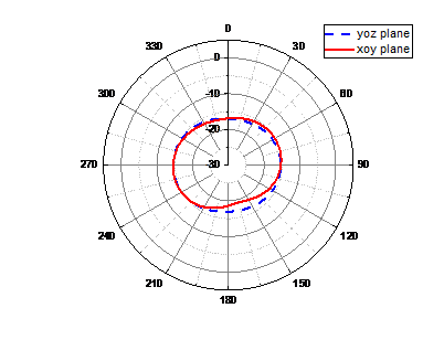
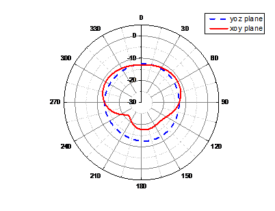
The measured radiation patterns of the fabricated prototype at 156 MHz, 380 MHz, 698 MHz, and 1800 MHz in the anechoic chamber with far-field system are shown in Figure 4. At 156 MHz, the antenna gain is relatively low, but an omnidirectional radiation pattern can be observed. At 380, 698 and 1800 MHz, similar radiation patterns are generally observed, which proves that this antenna has good omnidirectional radiation performance at different frequency points.
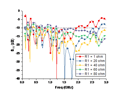
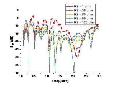
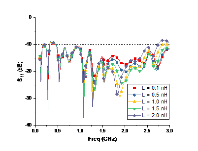
Figure 5 depicts the simulated S11 versus the values of R1, R2 and L1, respectively. Take R1 as an example. When the resistance value is small, the performance of S11 at high frequency and low frequency is not ideal. As the resistance increases, the impedance performance of the antenna gradually increases. However, as the resistance value continues to rise, the impedance performance in the low frequency band becomes poorer. It can be seen that the value of the loaded lumped device has a large impact on the antenna S11, and the value being either too high or too low will have a bad impact on the antenna impedance matching. So, choosing the appropriate lumped device value is critical to antenna performance.
(a) 156 MHz
(b) 380 MHz
(c) 698 MHz
(d) 1800 MHz
Figure 4. Measured radiation patterns
(a) R1
(b) R2
(c) L
Figure 5. Simulated S11 of the proposed antenna with variations of values
This paper presents the design and fabrication of a novel low-profile ultra-wideband indoor antenna formed by two slotted patches printed on a 0.8mm thick dielectric substrate. With the parallel and series resistors loaded, the surface current of the antenna is distributed in the form of traveling wave. It can effectively widen the impedance bandwidth of the proposed antenna. With the lumped elements loaded, the radiation efficiency of the antenna can be improved. The proposed antenna can cover an ultra-wide frequency band of 0.1 GHz-3.1GHz and maintains high efficiency over the whole band. What is more, the antenna has a compact and low-profile structure of 310×270×0.8 mm3. Considering the abovementioned attractive features, the proposed antenna can be used in electromagnetic field measurement, radio monitoring and visualization instruments.
[1] Schantz, H. (1993). The Art and Science of Ultra Wideband Antennas. Norwood, MA: Artech House, 2005 W.K. Chen, Linear Networks and Systems, Belmont, CA: Wadsworth, 123-135.
[2] Guo, D., He, K., Zhang, Y., Song, M. (2016). A multiband dual-polarized omnidirectional antenna for indoor wireless communication systems. IEEE Antennas and Wireless Propagation Letters, 16: 290-293. http://doi.org/10.1109/LAWP.2016.2573840
[3] Yin, Y., Liu, L., Zhang, M. (2011). A tapered slot antenna loaded with resistive delay lines. In 2011 IEEE International Symposium on Antennas and Propagation (APSURSI), pp. 3327-3329. http://doi.org/10.1109/APS.2011.6058695
[4] Mok, W.C., Wong, S.H., Luk, K.M., Lee, K.F. (2013). Single-layer single-patch dual-band and triple-band patch antennas. IEEE Transactions on Antennas and Propagation, 61(8): 4341-4344. http://doi.org/10.1109/TAP.2013.2260516
[5] Kim, K., Scott, W.R. (2005). Design of a resistively loaded vee dipole for ultrawide-band ground-penetrating radar applications. IEEE Transactions on Antennas and Propagation, 53(8): 2525-2532. http://doi.org/10.1109/TAP.2005.852292
[6] Lestari, A.A., Yarovoy, A.G., Ligthart, L.P. (2004). RC-loaded bow-tie antenna for improved pulse radiation. IEEE Transactions On Antennas and propagation, 52(10): 2555-2563. http://doi.org/10.1109/AGPR.2007.386551
[7] Guangyou, F. (2005). New design of the antipodal Vivaldi antenna for a GPR system. Microwave and Optical Technology Letters, 44(2): 136-139. http://doi.org/10.1002/mop.20568
[8] Schaubert, D., Kollberg, E., Korzeniowski, T., Thungren, T., Johansson, J.O.A.K.I.M., Yngvesson, K. (1985). Endfire tapered slot antennas on dielectric substrates. IEEE Transactions on Antennas and Propagation, 33(12): 1392-1400. http://doi.org/10.1109/TAP.1985.1143542
[9] Lestari, A.A., Yarovoy, A.G., Ligthart, L.P. (2003). Analysis of RC loading profiles for antenna bandwidth improvement. In IEEE Antennas and Propagation Society International Symposium. Digest. Held in conjunction with: USNC/CNC/URSI North American Radio Sci. Meeting (Cat. No. 03CH37450), 3: 632-635. http://doi.org/ 10.1109/APS.2003.1219927
[10] Jing, X., Du, Z., Gong, K. (2006). A compact multiband planar antenna for mobile handsets. IEEE Antennas and Wireless Propagation Letters, 5: 343-345. http://doi.org/10.1109/LAWP.2006.880690
[11] Hsu, C.K., Chung, S.J. (2010). A wideband DVB forked shape monopole antenna with coupling effect for USB dongle application. IEEE Transactions on Antennas and Propagation, 58(9): 3029-3036. http://doi.org/10.1109/tap.2010.2052545
[12] Liu, H.W., Ku, C.H., Yang, C.F. (2010). Novel CPW-fed planar monopole antenna for WiMAX/WLAN applications. IEEE Antennas and Wireless Propagation Letters, 9: 240-243. http://doi.org/10.1109/LAWP.2010.2044860
[13] Kim, S., Jeong, S., Lee, Y.T., Kim, D.H., Lim, J.S., Seo, K.S., Nam, S. (2002). Ultra-wideband (from DC to 110 GHz) CPW to CPS transition. Electronics Letters, 38(13): 622-623. http://doi.org/10.1049/el:20020423
[14] Butrym, A., Pivnenko, S. (2004). CPW to CPS transition for feeding UWB antennas. In 2004 Second International Workshop Ultrawideband and Ultrashort Impulse Signals (IEEE Cat. No. 04EX925), pp. 107-108. http://doi.org/10.1109/UWBUS.2004.1388063
[15] Kwon, D.H., Kim, Y. (2006). Suppression of cable leakage current for edge-fed printed dipole UWB antennas using leakage-blocking slots. IEEE Antennas and Wireless Propagation Letters, 5: 183-186. http://doi.org/ 10.1109/lawp.2006.873937
[16] Montoya, T.P., Smith, G.S. (1996). A study of pulse radiation from several broad-band loaded monopoles. IEEE Transactions on Antennas and Propagation, 44(8): 1172-1182. http://doi.org/10.1109/8.511827
[17] Yarovoy, A., De Jongh, R., Ligthart, L. (2000). Ultra-wideband sensor for electromagnetic field measurements in time domain. Electronics Letters, 36(20): 1679-1680. http://doi.org/10.1049/el:20001171
[18] Shlager, K.L., Smith, G.S., Maloney, J.G. (1994). Optimization of bow-tie antennas for pulse radiation. IEEE Transactions on Antennas and Propagation, 42(7): 975-982. http://doi.org/10.1109/8.299600
[19] Soboll, P., Wienstroer, V., Kronberger, R. (2016). Innovating RFID for future applications: A capacitive coupled antenna design for UHF RFID application. IEEE Microwave Magazine, 17(2): 65-69. http://doi.org/10.1109/MMM.2015.2498083
[20] Ryu, H.K., Lim, S., Woo, J.M. (2008). Design of electrically small, folded monopole antenna using C-shaped meander for active 433.92 MHz RFID tag in metallic container application. Electronics Letters, 44(25): 1445-1447. http://doi.org/10.1049/el:20082848
[21] Liu, W., Zhang, Z., Feng, Z. (2012). ISM 433-MHz miniaturized antenna using the shielding box of mobile terminals. IEEE Antennas and Wireless Propagation Letters, 11: 330-333. http://doi.org/10.1109/lawp.2012.2191379
[22] Buckley, J., Gaetano, D., McCarthy, K.G., Loizou, L., O'Flynn, B., O'mathuna, C. (2014). Compact 433 MHz antenna for wireless smart system applications. Electronics Letters, 50(8): 572-574. http://doi.org/10.1049/el.2013.4312
[23] Hettak, K., Delisle, G.Y., Tardif, S., Morin, G.A., Stubbs, M.G. (2008). A novel wideband Chebychev tapered slot antenna using broadband CPW to slotline transition. In 2008 IEEE Antennas and Propagation Society International Symposium, pp. 1-4. http://doi.org/10.1109/APS.2008.4620052
[24] Seino, K., Kuwabara, S., Mikami, S., Takahashi, Y., Yoshikawa, M., Narumi, H., Nagano, A. (2004). Development of the traceability system which secures the safety of fishery products using the QR code and a digital signature. In Oceans' 04 MTS/IEEE Techno-Ocean'04 (IEEE Cat. No. 04CH37600), 1: 476-481. http://doi.org/10.1109/OCEANS.2004.1402962
[25] Lee, E., Hall, P.S., Gardner, P. (1999). Compact wideband planar monopole antenna. Electronics Letters, 35(25): 2157-2158. http://doi.org/10.1049/el:19991491
[26] Chen, Z.N. (2000). Impedance characteristics of planar bow-tie-like monopole antennas. Electronics Letters, 36(13): 1100-1101. http://doi.org/10.1049/el:20000816
[27] Ammann, M.J. (2000). Impedance bandwidth of the square planar monopole. Microwave and Optical Technology Letters, 24(3): 185-187. http://doi.org/10.1002/(SICI)1098-2760(20000205)24:33.0.CO;2-8
[28] Ammann, M.J., Chen, Z.N. (2003). Wideband monopole antennas for multi-band wireless systems. IEEE antennas and Propagation Magazine, 45(2): 146-150. http://doi.org/10.1109/MAP.2003.1203133
[29] Chen, H.D. (2008). Compact broadband microstrip-line-fed sleeve monopole antenna for DTV application and ground plane effect. IEEE Antennas and Wireless Propagation Letters, 7: 497-500. http://doi.org/10.1109/LAWP.2008.2004213
[30] Chae, S., Yoshida, T. (2010). Application of RFID technology to prevention of collision accident with heavy equipment. Automation in Construction, 19(3): 368-374. http://doi.org/10.1016/j.autcon.2009.12.008
[31] Geng, J., Jin, R., Wang, W., He, W., Ding, M., Wu, Q., Fang, Z. (2007). A new quasi-omnidirectional vertical polarisation antenna with low profile and high gain for DTV on vehicle. IET Microwaves, Antennas & Propagation, 1(4): 918-924. http://doi.org/10.1049/iet-map:20060264
[32] Ammann, M.J., Chen, Z.N. (2003). A wide-band shorted planar monopole with bevel. IEEE Transactions on Antennas and Propagation, 51(4): 901-903. http://doi.org/10.1109/TAP.2003.811061
[33] Antonino-Daviu, E., Cabedo-Fabres, M., Ferrando-Bataller, M., Valero-Nogueira, A. (2003). Wideband double-fed planar monopole antennas. Electronics Letters, 39(23): 1635. http://doi.org/10.1049/el:20031087
[34] Wu, X.H., Chen, Z.N. (2005). Comparison of planar dipoles in UWB applications. IEEE Transactions on Antennas and Propagation, 53(6): 1973-1983. http://doi.org/10.1109/tap.2005.848471
[35] Yang, T., Davis, W.A. (2004). Planar half-disk antenna structures for ultra-wideband communications. In IEEE Antennas and Propagation Society Symposium, 3: 2508-2511. http://doi.org/10.1109/APS.2004.1331883
[36] Kwon, D.H., Kim, Y. (2004). CPW-fed planar ultra-wideband antenna with hexagonal radiating elements. In IEEE Antennas and Propagation Society Symposium, 3: 2947-2950. http://doi.org/10.1109/APS.2004.1331996
[37] Liang, J., Chiau, C.C., Chen, X., Parini, C.G. (2005). Printed circular ring monopole antennas. Microwave and Optical Technology Letters, 45(5): 372-375. http://doi.org/10.1002/mop.20827
[38] Choi, S.H., Park, J.K., Kim, S.K., Park, J.Y. (2004). A new ultra‐wideband antenna for UWB applications. Microwave and optical Technology Letters, 40(5): 399-401. http://doi.org/10.1002/mop.11392
[39] Liu, W.C., Wu, C.M., Chu, N.C. (2010). A compact CPW-fed slotted patch antenna for dual-band operation. IEEE Antennas and Wireless Propagation Letters, 9: 110-113. http://doi.org/10.1109/LAWP.2010.2044135
[40] Hsu, C.K., Chung, S.J. (2010). A wideband DVB forked shape monopole antenna with coupling effect for USB dongle application. IEEE Transactions on antennas and propagation, 58(9): 3029-3036. http://doi.org/10.1109/tap.2010.2052545
[41] Park, C.H., Rhyu, H.P., Kim, S.H., Jung, C.W., Lee, B.J. (2008). Internal DTV antenna on multilayered ferrite substrate for mobile phone applications. 2008 IEEE Antennas and Propagation Society International Symposium, pp. 1-4. http://doi.org/10.1109/APS.2008.4619463
[42] Véronneau, S., Roy, J. (2009). RFID benefits, costs, and possibilities: The economical analysis of RFID deployment in a cruise corporation global service supply chain. International Journal of Production Economics, 122(2): 692-702. https://doi.org/10.1016/j.ijpe.2009.06.038
[43] Chung, K., Park, H., Choi, J. (2005). Wideband microstrip‐fed monopole antenna with a narrow slit. Microwave and Optical Technology Letters, 47(4): 400-402. http://doi.org/10.1002/mop.21181
[44] Ban, Y.L., Qiang, Y.F., Chen, Z., Kang, K., Guo, J.H. (2014). A dual-loop antenna design for hepta-band WWAN/LTE metal-rimmed smartphone applications. IEEE Transactions on Antennas and Propagation, 63(1): 48-58. http://doi.org/10.1109/TAP.2014.2368573
[45] Wu, D., Cheung, S.W., Yuk, T.I. (2015). A compact and low-profile loop antenna with multiband operation for ultra-thin smartphones. IEEE Transactions on Antennas and Propagation, 63(6): 2745-2750. http://doi.org/10.1109/TAP.2015.2412962
[46] Liu, J.X., Yin, W.Y. (2010). A compact interdigital capacitor-inserted multiband antenna for wireless communication applications. IEEE Antennas and Wireless Propagation Letters, 9: 922-925. http://doi.org/10.1109/LAWP.2010.2073435