Dekali Zouheyr* | Baghli Lotfi | Boumediene Abdelmadjid
© 2021 IIETA. This article is published by IIETA and is licensed under the CC BY 4.0 license (http://creativecommons.org/licenses/by/4.0/).
OPEN ACCESS
This paper presents the design, modeling, simulation and the experimental implementation of a 1.5 kW relatively low-cost wind energy conversion system (WECS) based on the double fed induction generator (DFIG) configuration. In the preliminary experiments, we test the DFIG power control under fixe speed by applying the vector control principle, then we insert the physical emulator presented in the controlled DC motor in order to simulate the static-dynamic behaviors of a real wind turbine with the use of the Tip Speed Ratio TSR based MPPT algorithm to extract the maximum available power on the emulator. The proposed structure is simulated using MATLAB Simulink environment, the obtained results are validated experimentally on our laboratory setup. We also develop an application with MATLAB AppDesigner that calculates the operating point of our system at steady state and visualize the power transfer, current, voltage and electromagnetic torque values of the DFIG and the DC motor before starting the stimulation or the experimental manipulation. The MPPT, the DC motor control and the DFIG power control algorithms are implanted in C, embedded on a dSPACE DS1104 control board. The obtained results confirm the reliability of the proposed WECS to manage all the probable operating modes, also the effectiveness of the physical simulator in the role of wind turbine emulation.
wind energy conversion system, double fed induction generator, dc motor, wind turbine emulator, maximum power point tracking
In the last decade, the renewable energy exploitation knows a broad growth, especially the wind energy, thanks to the economic factor in the world markets, alternative and renewable source, and the ecological properties [1]. According the world wind energy association (WWEA), The overall capacity of all wind turbines installed worldwide by the end of 2019 reached 650 Gigawatt, with 60 GW added slightly more than in 2018 [2].
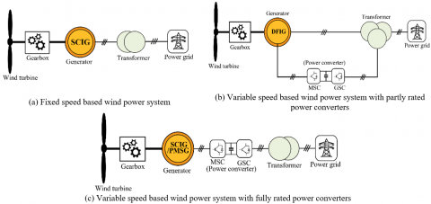
Mainly, the wind turbine systems can be divided into two basic operating classes. The first one, called the Fixed-Speed Concept or the “Danish concept”, is widely prevalent in the first WECS emerged systems. Its principle requires the direct connection of the generator which is mostly an IG induction generator to the power grid, and by consequence, this configuration can only operate at fixed rotational speed corresponding to the power grid frequency (Figure 1.a). The advantages of this concept are the simple structure, as well as the low cost compared to other configurations due to lack of the power converters. On the other hand, we cannot extract the maximum of the available power which changes with the variation in the wind speed. This is the major drawback. There is also the huge mechanical pulsation resulting from wind gusts [3, 4].
The second concept, which is widely used nowadays, which is the variable speed wind power system. It is divided into two classes:
Currently, the DFIG configuration represents one of the best techno-economic solutions for wind power generation. This configuration requires the direct connection of the DFIG stator to the power grid. The DFIG rotor is connected to the grid through power electronic converters which are mostly a two two-level pulse width modulation voltage source converter (2L-PWMVSC) and are configured in a back-to-back structure. This permits the control of the power transfer between the generator (stator-rotor) and the power grid using the rotor currents control loops during the operating modes (hypo and hyper synchronous modes), depending on wind speed variations. Consequently, the Maximum Power Point Tracking (MPPT) becomes possible for a maximum wind energy harvesting [7-9].
In many literatures, the DC motor is widely used in the emulators of mechanical inertia driving systems, because its linear model which ensures the proportionality between the armature current and the torque. This makes easier the implementation of speed and torque control with enough precision and at a reasonable cost [10, 11].
This paper presents an experimental approach of developing of an experimental bench for the emulation of a wind energy conversion chain based on a DFIG, at an affordable price, including its different elements (power electronics, machines and control). We will present the theory and the simulations as well as the steady state computation App. For the experiments, we will test the DFIG indirect power control under a fixed speed by adjusting the rotor current with PI controllers through a dual loop control. After achieving this, we test the setup under random wind turbine operating modes, by applying different wind data shape on the controlled DC motor to get the estimated aerodynamic torque by the action of a tip speed ratio TSR based maximum power point tracking MPPT control loop [12-15].
The paper parts are structured as follow: section 2 shows the DFIG control technique with its associated model. In section 3, the presentation of the proposed experimental workbench is given. In Section 4, we test the DFIG power control at a fixed speed by applying an active power reference with compensated and uncompensated reactive power. In the 5th section, we detail design, modeling, and insertion of the wind emulator with its integrated MPPT. Experimental results endorsed by the simulation ones are compared and interpreted for the performance evaluation of the DFIG power control and the emulator performances in section 6. Finally, we present conclusions and perspectives.
Figure 1. WECS types
The DFIG power converters consist in two two-level pulse-width-modulation voltage source converter (2L-PWMVSC) which are configured in a back-to-back structure. The first one is called the machine side converter (MSC). It imposes the current references for reaching the desired DFIG active and reactive power using the stator-flux vector control. The machine side converter (MSC) is powered by a second 6-IGBT inverter which is called grid side converter (GSC) through a DC link contains a filtering capacitor. The GSC main role is the control of direction and the power consumed or injected into the grid by acting on the phase’s currents. For our experimental setup, a diode-based 3-phases rectifier is sufficient as a grid side converter, which reduces the costs and also the control complexity. Hence, the generated power under the hypersynchronous mode is exploited to power the DC motor through the chopper [8, 16].
The DFIG indirect power control requires the application of the field-oriented control. Therefore, we need to express the machine model in a dq reference frame with the generally admitted assumptions [13].
We chose to orient the reference frame such that the stator flux vector is entirely hold on the q axis. Hence, the stator voltage vector remains on the d axis. The expression of the stator power as a function of the rotor currents shows the linearity of the obtained decoupled model [12, 17].
$P_{s}=-\frac{M V_{s}}{L_{s}} I_{q r}$ (1)
$Q_{s}=-\frac{M V_{s}}{L_{s}} I_{d r}+\frac{V_{s}^{2}}{\omega_{s} L_{s}}$ (2)
The action on Idr is responsible for the control of the reactive power Qs, although, the Iqr is for the active power Ps control. The actual rotor voltages are given by [8]:
$V_{d r}=R_{r} I_{d r}+\sigma L_{r} \frac{d I_{d r}}{d t}-\omega_{r} \sigma L_{r} I_{q r}$ (3)
$V_{q r}=R_{r} I_{q r}+\sigma L_{r} \frac{d I_{q r}}{d t}+\omega_{r} \sigma L_{r} I_{d r}+\omega_{r} \frac{M V_{s}}{\omega_{s} L_{s}}$ (4)
The main advantage of this strategy is the independent and instantaneous control of both stator powers (Qs, Ps) by acting on the rotor currents (Idr, Iqr) thanks to the PI controllers. The reference steps (Qs*or Idr*), (Ps*or Iqr*) are imposed according to the needs. Figure 2 represents the overall DFIG indirect control diagram [15, 16].
Figure 2. DFIG MSC power control principle
Figure 3. Experimental configuration
The proposed experimental bench that emulates the DFIG wind power system is given in Figure 3. The auto-transformer that connects the DFIG stator with the grid has the role of the voltage adjusting, on the other hand, it transforms the main produced energy to the grid. The second auto-transformer is used to supply the rotor through the power electronic converters. We use a grid side converter (GSC) composed of a 6-diodes rectifier, followed by a 6-IGBT inverter (MSC) to power the DFIG rotor [12, 18, 19].
The DFIG rotor is mechanically coupled to the DC motor. This latter acts for the physical simulator of a real wind turbine. The chopper that drives the DC motor share the same DC voltage supply with the DFIG MSC in order to reduce experimental bench costs. This allows to use a rectifier as grid side converter (GSC) instead of an inverter, hence, when the emulator will be in hypersynchronous mode, the DC motor chopper absorbs the active power generated by the rotor of the DFIG.
The DC bus voltage must be adapted to the maximum value of the DC motor voltage and the DFIG rotor coils voltage. This latter is generally lower than the stator voltage for a usual lab induction machine.
In our setup, one dSPACE DS1104 control board is enough to drive both the DC motor and the DFIG. This control board generates one PWM signal to drive the chopper of the DC motor in order to impose the driving torque of the wind turbine emulator. It also generates 6 PWM signals to control the MSC that imposes the needed rotor currents.
The power electronic converter is the integrated SEMIKRON Semiteach box which contain a 6-diodes rectifier (GSC), a 6-IGBT inverter (MSC) and a braking chopper used as the DC motor chopper.
The DS1104 ADCs are used to input the current and voltage measurements. We developed measurement boards based on the Hall effect LEM sensors. Hence, we use the LEM LA55 sensors for the rotor currents and the DC motor current measurements, and the LEM LV25-P sensors for two stator and the DC bus voltages.
The supervision of the setup variables in real time are done thanks to Control Desk™ software running on the DS1104 host PC.
The lab set up is shown below in appendix in Figure 30, while the hardware components are exposed in Table 1. The nominal parameters of the experimental bench are given in Tables 2, 3 and 4.
In this part, to evaluate the performances of the indirect power control of the DFIG using the dual PI loops, we will simulate this system and make experimental tests for the control of the active and reactive power at fixed speed. Therefore, we implement the proposed structure on the Matlab Simulink framework. In addition, we create a software application by Matlab App Designer, which helps us to calculate the operating point of our system at steady state, and visualize the power transfer, current, voltage and electromagnetic torque values of the DFIG before starting the stimulation or the experimental operation.
4.1 The App Designer application for the DFIG steady state
App Designer is a framework to create professional software applications in Matlab (version > 2016). It is almost based on the same aspects and controls as the former GUI (Graphical User Interface). The App Designer consists of two main tasks: a tool bar contains a visual component ready to use with its integrated program. Dropping the element to the workspace activates it. The embedded programming editor allows to add new properties, callbacks and other functions. The quick switch between the visual design and the app code makes it easier to understand, modified and run it. Add to that, the Matlab Compiler allows transform this app into a standalone desktop and web apps with its own installation package and share them royalty free [20, 21]. For our application, we can select if one introduces the value of the power (Qs, Ps) and calculates the currents (Idr, Iqr) respectively, or the opposite.
In the editor code, we establish the DFIG steady state model, the rotor voltages become [22]:
$V_{d r}=R_{r} I_{d r}-\omega_{r} \sigma L_{r} I_{q r}$ (5)
$V_{q r}=R_{r} I_{q r}+\omega_{r} \sigma L_{r} I_{d r}+\omega_{r} \frac{M V_{s}}{\omega_{s} L_{s}}$ (6)
The stator power formula (Qs, Ps) remains the same as in Eq. 1 and Eq. 2. The inverse relationship of rotor currents is given by [16]:
$I_{q r}=-\frac{L_{s}}{M V_{s}} P_{s}$ (7)
$I_{d r}=-\frac{L_{s}}{M V_{s}} Q_{s}+\frac{V_{s}}{\omega_{s} M}$ (8)
For the transient experiments, we apply two tests:
4.2 First test: Active power reference step
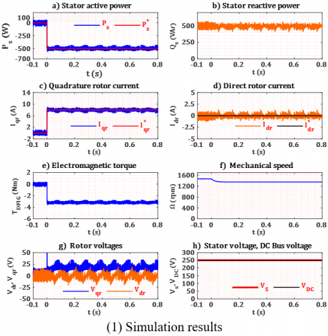
Figure 4. Test results on a reference step of Ps* = -500 W
Figure 4 shows the results when a reference step of Ps* = -500 W is applied. The power is generated and injected into the grid during the entire test, this is why Psis a negative value. The reactive power is not compensated, so the machine absorbs the needed power to get fluxed (Qs = 450 VAr). This value is normal for an induction motor. It needs to magnetize itself from the stator, which is not the case for a synchronous motor. Figure (4.1.a, 4.2.a) shows tracking accuracy between the measured Ps and the reference variables Ps* with some oscillations in steady state, thanks to the control of the rotor currents (Idr, Iqr) that follow correctly their references (Idr*, Iqr*) (4.1.c, 4.2.c) and (4.1.d, 4.2.d) respectively. We have only current control of the dq rotor currents components and no power control in the implementation of this indirect DFIG control scheme. The DFIG mechanical speed decreases a little (4.1.f, 4.2.f) because of the strong demand on torque at t=0(4.1.e, 4.2.e). There is a ripple on the stator voltage (Vs=Vqs) because of the current demand which influences the voltage of the secondary of the autotransformer used to connect the stator to the grid. This has also affected on the estimated active and reactive power. The DFIG rotor currents have also ripples due to measurement, PWM and noise. Hence, the rotor voltage references (Vdr, Vqr) are generated by the PI current controllers in order to compensate these variations (4.1.g, 4.2.g). The DC bus voltage is also affected, especially, on transients when there is a huge demand in currents that drops the DC bus voltage (4.2.h). For the simulation, we use a perfect DC source. Thus, The DC bus voltage stays constant in (4.1.h).
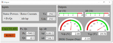
The experimental results are quite identical to the simulation ones. Figure 5 present the App Designer software interface of the DFIG steady state for the reference step of Ps* = -500 W. The values indicated on the app interface are accurate and match the ones of the previous test, in steady state, for both the experiment and the simulation.
The experimental and simulation curves of the currents and powers are the same thanks to the current controllers as we feed the loops with the same references. The output of the controllers Vdr and Vqr references differs a little. This is due to the non-perfect DC bus voltage that, in the experiments, has a drop when the load is applied. The mechanical speed dynamic is also slightly different due to a slight mismatch between the actual and the model estimation of the inertia of the rotor shaft and the friction coefficients.
Figure 5. DFIG steady-state App interface for Ps* = -500 W
4.3 Second test: Reactive power reference step
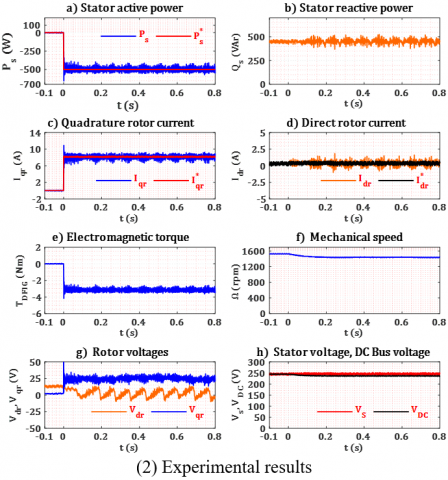
The high dynamic performances of the DFIG power control in this test are similar to that of the first test (Figure 6). Therefore, we compensate the reactive power by applying a reference step of Qs* = 0 VAr. We set the Ps* at -500 W as in the previous test.
The measured reactive power Qs follows its reference Qs* accurately from 450 VAr to 0 VAr at the initial moment (6.1.b, 6.2.b), while the active (generated) power remains at -500 W (6.1.a, 6.2.a). This is of course due to the control of the (Idr, Iqr) currents that follow their references (Idr*, Iqr*) accurately (6.1.c, 6.2.c), (6.1.d, 6.2.d). The speed is less disturbed than in the previous test because there is no change on the torque demand (6.1.f, 6.2.f). The DC bus voltage VDC is also not disturbed (6.1.h, 6.2.h).
Figure 6. Test results on a reference step of Qs* = 0 Var
Figure 7. DFIG steady-state App interface for Qs*=0VAr
The Figure 7 presents the App Designer software interface of the DFIG steady state for the total compensation of the reactive power Qs* = 0 VAr with an active power reference Ps* = -500 W. The values shown on the application interface are hence again accurate. Therefore, this interface is a useful tool to ensure the correct results, especially for the pre-definition of the hardware protection limits.
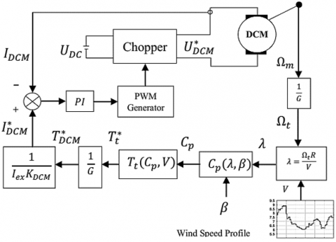
Figure 8. Schematic of the proposed WTE
The main idea of this part requires the addition of a DC motor control loop in order to obtain a DFIG drive torque identical to a real aerodynamic torque, for that, we apply a DC motor armature reference current which is calculated by applying a wind speed profile on the real model of a wind turbine, the resulting torque is proportional to the armature current, consequently, the mechanical speed, which will be controlled through another control loop by introducing the tip speed ratio (TSR) based MPPT algorithm [23].
The used hardware emulator is made of a controlled DC motor which is connected mechanically to the DFIG shaft, which in turn takes its supply from the same DC bus voltage shared with the DFIG rotor inverter (Figure 8) [24-26].
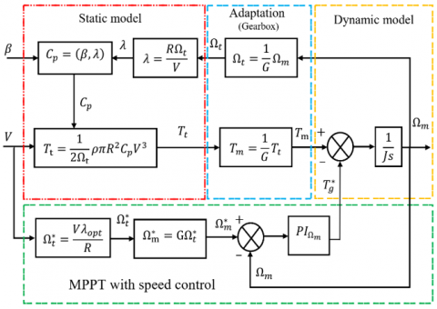
5.1 WTE static model
Generally, the desired produced power in the WECS is dependent mainly on the variety of the turbine dimensions (the length and radius of the blades, tower altitude...), and the power coefficient that is given by the constructor [14]. The most known formula for the power coefficient is given by:
$C_{p}=0.5176\left(\frac{116}{\lambda_{i}}-0.4 \beta-5\right) \exp \left(\frac{-21}{\lambda_{i}}\right)+0.0068 \lambda$ (9)
with:
$\frac{1}{\lambda_{i}}=\frac{1}{\lambda+0.08 \beta}-\frac{0.035}{\beta^{3}+1}$ (10)
The part of the mechanical power extracted from the kinetic energy of wind is expressed as follows [19]:
$P_{m}=\frac{1}{2} \rho A C_{p} V^{3}$ (11)
The power coefficient decreases according to the evolution of the tip speed ratio (TSR) and β value in the WECS with variable blades pitch angle. The more β increases, the more Cp decreases and consequently the extracted energy decreases (Figure 9.a) [11, 19].
The generated energy amount is linked to the mechanical speed of the generator because of the wind speed variations (Figure 9.b). Hence, it is necessary to apply the MPPT algorithm to reach the vertices of the power coefficient curves for each given wind speed (Figure 11), thus, extracting as much possible the maximum power available on the turbine shaft [27].
5.2 WTE dynamic model
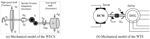
The WECS dynamic model based on the two-mass model is illustrated in (Figure 10.a). The torque-speed adaptation is done thanks to a gearbox between the high and low speed shafts. Tg is the load torque or the DFIG electromagnetic torque and Ttis the aerodynamic torque. G is the gear speed ratio [19, 24].
The stiffness coefficients of the turbine and the generator (dtand dg) are usually weak, so they can be neglected. dG and fG are the stiffness and damping coefficient of the gearbox bridge, ft and fg are the friction coefficients of the turbine and the generator, respectively. The fundamental mechanical model can hence be expressed as:
$\frac{T_{t}}{G}-T_{g}=\left(\frac{J_{t}}{G^{2}}+J_{g}\right) \frac{d \Omega_{m}}{d t}$ (12)
Figure 10.b presents the dynamic model of the implanted wind turbine emulator, the equivalent mechanical equation is given as follows [14]:
$T_{D C M}-T_{g}=\left(J_{D C M}+J_{g}\right) \frac{d \Omega_{m}}{d t}$ (13)
5.3 TSR based MPPT algorithm implementation
Figure 11. TSR principle based MPPT algorithm
Figure 12. TSR based MPPT algorithm block diagram
The tip speed ratio based MPPT algorithm consists into keeping the speed ratio at its optimum value, that corresponds to the maximum value of Cp for any wind velocity, hence, extracting the most available power on the shaft (Figure 11) [28, 29].
This algorithm is simple and easy to implement with only one PI controller for the speed control loop (Figure 12). However, it requires the knowledge of the wind speed, generally ensured by an anemometer placed near the WT, and consequently disturb wind speed the measure [11, 29].
To evaluate the performances of the whole system with the addition of the WTE, we test the control structure under different wind speed profiles that covers the MPPT operating mode. The variable wind allows hypo-synchronous and hyper-synchronous operating conditions.hypo-synchronous and hyper-synchronous ones. All the simulation tests are applied thanks to Matlab/Simulink and are validated experimentally on the experimental test bench after taking into account the values obtained by the software application.
6.1 Hypo synchronous mode
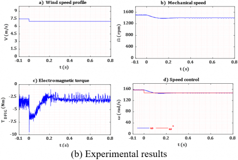
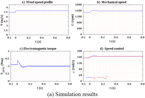
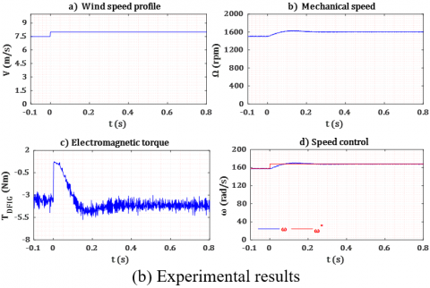
Figure 13. WTE Mechanical characteristics
To test the structure in hypo synchronous operating mode, we apply a wind reference step which begins with the synchronous speed corresponding to 7.5 m/s and decrease down to 7 m/s (Figure 13). The applied step causes an instantaneous decrease in the speed reference accompanied by a decrease in electromagnetic torque because of the speed control loop based MPPT algorithm that imposes the speed and torque references. The generator needs more torque in the beginning in order to rapidly slow down the WTE according to the speed reference step, then the torque comes back to a lower value in steady state.
The DC motor torque that we made equal to the aerodynamic torque is expressed as a function of the wind data and the static-dynamic model of the wind turbine. Therefore, the wind data imposes the DC motor current reference, and consequently, the needed DC motor voltage, to achieve the desired drive torque (Figure 14).
Figure 14. DC motor control
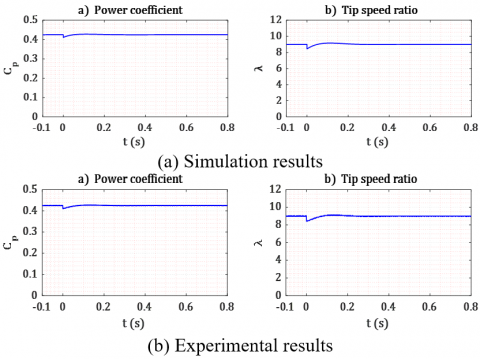
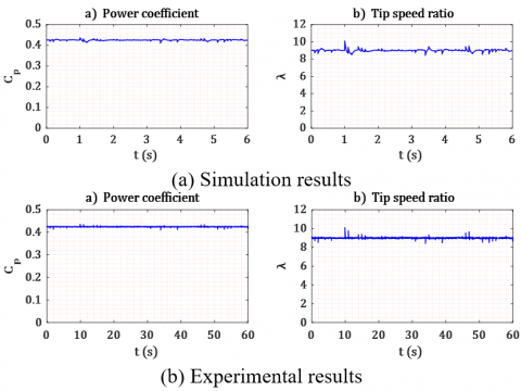
The power coefficient and the tip speed ratio keep their values around the optimum during the entire test with a fast peak at the starting (Figure 15).
Figure 15. WTE Static characteristics
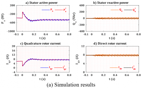
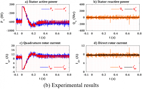
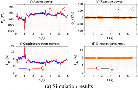
The active power reference is defined through the MPPT loop in order to extract as much power as possible, as a result, it has the same shape as the wind data. The instantaneous height at the start is due the torque demand in order to slow down the WTE speed, so the generator produces more power in a moment accompanied by a peak at the Iqr current. The high efficiency of the PI controllers provides better tracking accuracy between the measured rotor currents and its references and ensures the desired powers. The reactive power is compensated, so the machine is fluxed through Idr = 8 A and not from the stator (Qs = 0 VAr). The spikes on the experimental results are due to high frequency noise from the measured rotor current. The lowpass filter bandwidth is chosen wide to avoid any lag in the current measurement, but it let pass more high-frequency contents (Figure 16).
Figure 16. DFIG Stator power control
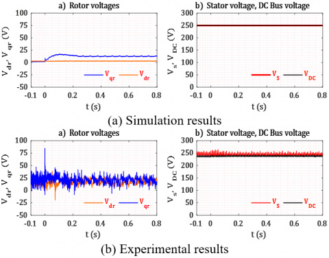
Figure 17. DFIG rotor, stator and DC bus voltages
Figure 17 shows the needed rotor voltages to reach the desired active and reactive stator power. The spikes on the experimental curves are caused by the control loops and the inverter switches. The DC bus voltage and the stator voltage remains at 250 V and they are less influenced by these harmonics.
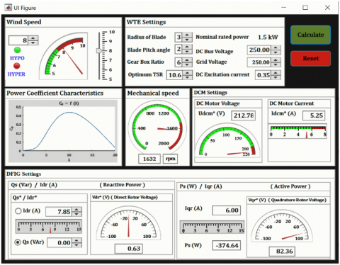
The obtained calculus results from App designer of the WTE steady-state applied in the hypo synchronous mode are relatively correct, there are slightly imbalanced, due to uncertainties in the identification of the parameters of the both machines (Figure 18).
Figure 18. WTE steady-state App interface for hypo synchronous mode
6.2 Hyper synchronous mode
Figure 19. WTE Mechanical characteristics
Figure 20. DC Motor control
Figure 21. WTE Static characteristics
Testing under the hypersynchronous operating mode requires the use of a wind reference data of 8 m/s. The mechanical speed necessarily goes up thanks to the speed regulation loop, as well as for the electromagnetic torque (Figure 19). However, we notice the transient on the torque, then even drive the generator into a motor mode with a positive torque, in order to accelerate and follow the speed reference.
The DC motor demand a higher value of DC voltage because of risen speed, but it remains below the limit. The PI controller guarantees perfect reference tracking of the measured armature current (Figure 20).
The power coefficient is always around 0.42, the tip speed ratio takes its optimal value for a fixed pitch angle of 2 degrees. The drop in the Cp and TSR are due to the sudden change on the wind speed. (Figure 21).
The production of stator active energy increases in proportion to the wind speed evolution, including the quadrature rotor current. The results of the active power and the quadrature rotor current have, at first, a noticeable drop and even a positive power, meaning the DFIG is briefly in motor mode, in order to rapidly increase the WTE speed to match the desired one. After this transient, the generated power is more important than before the wind velocity step. The stator reactive power is always compensated (Figure 22).
The q axis component of the rotor voltage is responsible for the change of the active power, whereas the d axis component controls the reactive power, the simulation curves show clearly their values (Figure 23).
The App values for this operating mode are approximately true as previous (Figure 24). This application is very useful, especially for the hypersynchronous running in order to clearly determine the limitations of the hardware protection (VDC Motor).
Figure 22. DFIG Stator power control
Figure 23. DFIG rotor, stator, and DC bus voltages
Figure 24. WTE steady-state App interface for hypo synchronous mode
6.3 Real wind speed profile
For this test, to be closer to the emulation of the actual behavior of a wind turbine power plant, we use real wind speed data, which contain random values around the synchronism speed (7.5 m/s). This benchmark requires the slow transition between the operating modes on a wide range of time. The speed control loop graphs show the same high dynamic performances as the previous experiments. Therefore, the mechanical speed increases and decreases gradually according to the applied mode, ensuring the speed tracking control (Figure 25).
Figure 25. WTE Mechanical characteristics
When the wind speed reference reaches a value higher than the limitation speed, the DC motor needs more electromotive force, but if the DC motor voltage supply reaches its limit at 220 V, the DC motor current is no longer controlled and falls below its reference. In the simulation, the DC motor voltage limitation is not inserted, in order to show the differences with the experiments at these high wind speeds (Figure 26).
The power coefficient has many small oscillations during the test due to the high frequency of the wind speed, but it remains close to its nominal value and far from the Betz limit (0.59). The tip speed ratio is influenced also by these ripples (Figure 27).
Figure 26. DC Motor control
Figure 27. WTE Static characteristics
The stator reactive power remains compensated at 0 VAr. The DFIG generates the power defined by the MPPT loop, thanks to the PI rotor currents controllers. Thus, it demonstrates the system reliability against operating mode changes. The ripples, on the experimental measurements, have a maximum of 25%, which remains satisfactory (Figure 28).
These ripples are of high frequency and can be lessened by imposing a less reactive MPPT algorithm to smoothly change the active power reference on wind changes. We notice in the experiments, while the DC motor current is not controlled, at the very high speed, the produced active power falls to zero. This does not happen in the simulation, where we did not put the limitation on the DC motor voltage.
The quadrature rotor voltage Vqr is directly linked to the active power reference, which explains the large variations. Whereas, Vdr is stable because there are no changes on the stator reactive power demand (Figure 29).
Figure 28. DFIG Stator power control
Figure 29. DFIG rotor, stator, and DC bus voltages
This paper presents a DFIG-based wind energy conversion system, including power control loops and high performance TSR-based MPPT algorithm. It shows the effectiveness of the proposed physical wind turbine emulator, under several operating modes.
The DFIG is one of the best techno-economic solutions for wind farms around the world, because of the reduced cost compared to the variable speed-based wind power system with fully rated power converters. Moreover, it allows direct connection of the stator to the grid. The control of the transferred power using the rotor currents allows 1/3rd of the power rating for the rotor side inverter / rectifier, in order to achieve a nominal power transfer from the stator to the power grid.
The experimental results, as well as the simulation ones, confirm that linear PI controllers are adequate for these control performances, either for the rotor currents or for the WTE speed.
This experimental WTE will be used in our lab to test nonlinear control laws to achieve more performances. Moreover, it is a useful educational tool in order to train expert engineers and researchers in the field of production of renewable energies according to national needs in MENA region.
This work is supported by the Direction Generale de la Recherche Scientifique et du Developpement Technologique (DG RSDT).
|
DFIG |
Double fed induction generator |
|
DCM |
DC Motor |
|
WECS |
Wind energy conversion system |
|
WTE |
Wind turbine emulator |
|
MPPT |
Maximum power point tracking |
|
TSR |
Tip speed ratio |
|
TDFIG |
DFIG electromagnetic torque |
|
TDCM |
DC Motor torque |
|
Tt |
Turbine torque |
|
J |
Moment of inertia |
|
f |
Viscous friction coefficient |
|
V |
Wind speed, m/s |
|
CP |
Power coefficient |
|
R G |
Blade radius, m Gear box ratio |
|
λ |
The tip speed ratio |
|
b |
The blade pitch angle |
|
Ωm |
The mechanical speed, rpm |
|
Γ |
The torque |
|
ρ |
Air density, kg/m3 |
Table 1. WTE hardware component
|
Component |
Name |
|
1, 2 |
Autotransformer (stator side, rotor side respectively) |
|
3, 4 |
DFIG & DCM respectively |
|
5 |
PC |
|
6 |
Inverter and Rectifier |
|
7 |
Fluke 43B Power Quality Analyzer |
|
8, 9 |
Measure interfaces (DCM & DFIG respectively) |
|
10 |
DS1104 interface |
|
11 |
Rheostat |
|
12 |
VS, VDC Measures |
|
13 |
Power supply (DCM excitation) |
Table 2. WTE settings
|
Parameter |
Value |
|
Nominal power Pn |
1.5 kW |
|
Nominal speed Ωn |
1500 rpm |
|
Blade radius R |
3 m |
|
Gearbox ratio G |
7 |
|
Pitch angle β |
2° |
|
Optimum speed ratio λopt |
11.68 |
|
Air density ρ |
1.225 |
Table 3. The circuit parameters of the DC motor model
|
Parameter |
Value |
|
Nominal power Pn |
1.5 kW |
|
Nominal speed Ωn |
1500 rpm |
|
Nominal voltage Vn |
220 V |
|
Nominal armature current In |
9 A |
|
Armature resistance Ra |
3.5 Ω |
|
Armature inductance La |
0.0029 H |
Table 4. The circuit parameters of the DFIG model
|
Parameter |
Value |
|
Nominal power Pn |
1.5 kW |
|
Nominal speed Ωn |
1340 rpm |
|
Nominal voltage Vn |
220/400 V |
|
Nominal armature current In |
3.7 A |
|
Stator resistance Rs |
3.6 Ω |
|
Rotor resistance Rr |
0.337 Ω |
|
Stator inductance Ls |
0.406 H |
|
Rotor inductance Lr |
0.0235 H |
|
Mutual inductance M |
0.227 H |
|
Number of pole pairs P |
2 |
Figure 30. Lab Hardware setup
[1] Hau, E. (2013). Wind Turbines. Springer Berlin Heidelberg, Berlin, Heidelberg.
[2] World Wind Energy Association WWEA. Global Wind Instalations. https://wwindea.org/, accessed on Jan. 17, 2020.
[3] Xu, D., Blaabjerg, F., Chen, W., Zhu, N. (2018). Advanced Control of Doubly Fed Induction Generator for Wind Power Systems. John Wiley & Sons, 1-20.
[4] Xu, D., Blaabjerg, F., Chen, W., Zhu, N. (2018). Advanced Control of Doubly Fed Induction Generator for Wind Power Systems. John Wiley & Sons, 21-42.
[5] Muyeen, S.M. (2012). Wind Energy Conversion Systems. Springer London, London.
[6] Han, K., Chen, G.Z. (2009). A novel control strategy of wind turbine MPPT implementation for direct-drive PMSG wind generation imitation platform. In 2009 IEEE 6th International Power Electronics and Motion Control Conference, pp. 2255-2259. https://doi.org/10.1109/IPEMC.2009.5157778
[7] Blaabjerg, F., Xu, D., Chen, W., Zhu, N. (2018). Modeling of DFIG Wind Power Systems. Advanced Control of Doubly Fed Induction Generator for Wind Power Systems, Hoboken, NJ, USA: John Wiley & Sons, Inc., 65-97. https://doi.org/10.1002/9781119172093.ch4
[8] Blaabjerg, F., Xu, D., Chen, W., Zhu, N. (2018). Control of DFIG Power Converters. Advanced Control of Doubly Fed Induction Generator for Wind Power Systems. Hoboken, NJ, USA: John Wiley & Sons, Inc., 99-138.
[9] Chau, T.K., Yu, S.S., Fernando, T.L., Iu, H.H.C., Small, M. (2017). A novel control strategy of DFIG wind turbines in complex power systems for enhancement of primary frequency response and LFOD. IEEE Transactions on Power Systems, 33(2): 1811-1823. https://doi.org/10.1109/TPWRS.2017.2726160
[10] Arévalo, F., Estrada, P., Pozo, N., Pozo, M. (2017). Wind generation emulator using a DC machine. In 2017 IEEE Second Ecuador Technical Chapters Meeting (ETCM), 1-6. https://doi.org/10.1109/ETCM.2017.8247447
[11] Martinez, F., Herrero, L.C., de Pablo, S. (2014). Open loop wind turbine emulator. Renewable Energy, 63(2014): 212-221. https://doi.org/10.1016/j.renene.2013.09.019
[12] Dekali, Z., Baghli, L., Boumediene, A., Djemai, M. (2018). Control of a grid connected DFIG based wind turbine emulator. 5th International Symposium on Environment-Friendly Energies and Applications, Rome, pp. S1-S6.
[13] Dekali, Z., Baghli, L., Boumediene, A. (2018). Experimental implantation of an emulator of a wind energy conversion chain system based on double fed induction generator. 11th Scientific and Technical Days Innovation and Partnership in a Global Context of Energy Transition, Oran, pp. S1-S6.
[14] Dekali, Z., Baghli, L., Boumediene, A. (2019). Experimental emulation of a small wind turbine under operating modes using DC motor. In 2019 4th International Conference on Power Electronics and Their Applications (ICPEA), pp. 1-5. https://doi.org/10.1109/ICPEA1.2019.8911194
[15] Dekali, Z., Baghli, L., Boumediene, A. (2019). Indirect power control for a grid connected double fed induction generator based wind turbine emulator. In 2019 International Conference on Advanced Electrical Engineering (ICAEE), pp. 1-6.
[16] Yaichi, I., Semmah, A., Wira, P. (2019). Direct power control of a wind turbine based on doubly fed induction generator. European Journal of Electrical Engineering, 21(5): 457-464. https://doi.org/10.18280/ejee.210508
[17] Huang, K., Chen, G., Huang, S., Cai, L. (2009). Experimental evaluation of sensorless control for doubly-fed induction wind power generator. In 2009 International Conference on Electrical Machines and Systems, pp. 1-6. https://doi.org/10.1109/ICEMS.2009.5382826
[18] Mensou, S., Essadki, A., Nasser, T., Idrissi, B.B., Tarla, L.B. (2020). Dspace DS1104 implementation of a robust nonlinear controller applied for DFIG driven by wind turbine. Renewable Energy, 147: 1759-1771. https://doi.org/10.1016/j.renene.2019.09.042
[19] Moussa, I., Bouallegue, A., Khedher, A. (2019). New wind turbine emulator based on DC machine: Hardware implementation using FPGA board for an open-loop operation. IET Circuits, Devices & Systems, 13(6): 896-902. https://doi.org/10.1049/iet-cds.2018.5530
[20] Valle, J.M.G., García, J.C.C., Cadaval, E.R. (2017). Electric vehicle monitoring system by using MATLAB/App Designer. In 2017 International Young Engineers Forum (YEF-ECE), pp. 65-68. https://doi.org/10.1109/YEF-ECE.2017.7935642
[21] Tara, K., Sarkar, A.K., Khan, M.A.G., Mou, J.R. (2017). Detection of cardiac disorder using MATLAB based graphical user interface (GUI). In 2017 IEEE Region 10 Humanitarian Technology Conference (R10-HTC), pp. 440-443. https://doi.org/10.1109/R10-HTC.2017.8288994
[22] Lin, X., Xiahou, K.S., Liu, Y., Wu, Q.H. (2018). Design and hardware-in-the-loop experiment of multiloop adaptive control for DFIG-WT. VIEEE Transactions on Industrial Electronics, 65(9): 7049-7059. https://doi.org/10.1109/TIE.2018.2798566
[23] Saleh, S., Farag, A. (2019). Review fixed-speed wind turbine control strategies for direct grid connection. European Journal of Electrical Engineering, 21(3): 309-315. https://doi.org/10.18280/ejee.210308
[24] Balaji, M., Sarangi, S.K., Pattnaik, M. (2019). Design of a DC motor based wind turbine emulator using sliding mode control approach. In 2019 IEEE 1st International Conference on Energy, Systems and Information Processing (ICESIP), pp. 1-5. https://doi.org/10.1109/ICESIP46348.2019.8938228
[25] Moness, M., Moustafa, A.M. (2020). Real-time switched model predictive control for a cyber-physical wind turbine emulator. IEEE Transactions on Industrial Informatics, 16(6): 3807-3817. https://doi.org/10.1109/TII.2019.2937549
[26] Sajadi, A., Rosłaniec, Ł., Kłos, M., Biczel, P., Loparo, K.A. (2016). An emulator for fixed pitch wind turbine studies. Renewable Energy, 87(2016): 391-402. https://doi.org/10.1016/j.renene.2015.10.033
[27] Aguilar, M.E.B., Coury, D.V., Reginatto, R., Monaro, R.M. (2020). Multi-objective PSO applied to PI control of DFIG wind turbine under electrical fault conditions. Electric Power Systems Research, 180: 106081. https://doi.org/10.1016/j.epsr.2019.106081
[28] Karabacak, M., Fernandez-Ramirez, L.M., Kamal, T., Kamal, S. (2019). A new hill climbing maximum power tracking control for wind turbines with inertial effect compensation. IEEE Transactions on Industrial Electronics, 66(11): 8545-8556. https://doi.org/10.1109/TIE.2019.2907510
[29] Martínez-Márquez, C.I., Twizere-Bakunda, J.D., Lundback-Mompó, D., Orts-Grau, S., Gimeno-Sales, F.J., Seguí-Chilet, S. (2019). Small wind turbine emulator based on Lambda-CP Curves obtained under real operating conditions. Energies, 12(13): 2456. https://doi.org/10.3390/en12132456