Shailesh Kumar Gupta* | MohdArif Khan | Omveer Singh
© 2021 IIETA. This article is published by IIETA and is licensed under the CC BY 4.0 license (http://creativecommons.org/licenses/by/4.0/).
OPEN ACCESS
This paper proposes pulse width modulation schemes for a two-level five-phase voltage source inverter. According to the literature, the generation of a pure sinusoidal waveform requires an (n-1) number of vectors for 'n' number of phases, so in a five-phase system, a minimum of four-vectors is needed to generate a sinusoidal waveform. The author uses only two large vectors in this paper for a five-phase voltage source inverter. Vector diagram, switching table, and switching waveform have presented for two adjacent large space vectors. The performance for each PWM scheme is analyze based on fundamental components and total harmonic distortion. In last, results have verified in the Simulink environment.
space vector pulse width modulation, five phase VSI, total harmonic distortion, switching, simulation
Variable speed AC drives are needed in various industrial applications such as traction, electric and hybrid-electric vehicles, and ship propulsion. Typically, a three-phase machine is used to obtain a balanced output for this purpose, but it has some power limitations. To address these limitations in terms of increased efficiency, researchers are looking into polyphase machines rather than three-phase machines. Polyphase machines have many advantages over three-phase machines, including a lower volume-to-weight ratio, lower dc-link current harmonics, reduced rotor current harmonics, improved noise and vibration characteristics, and so on [1, 2]. In 1969, the first five-phase induction motor, which was the first step toward a polyphase system, was investigated [3]. Three-phase machines have a single stator current component around the d-q axis, while five-phase machines have more than one stator current component as the axis increases [4, 5]. The induced torque increases as the number of additional components increases. This property distinguishes the five-phase system from the three-phase system.
The five-phase induction motor requires a device that can provide a balanced five-phase output supply, such as a five-phase inverter. The input of this inverter is a dc source, and the output is a balanced voltage and frequency with a five-phase AC. For controlling the performance of a five-phase VSI, a variety of control schemes are available, but the space vector pulse width modulation scheme is the most common due to its benefits and ease of digital implementation. The literature provides a thorough description of the SVPWM for the five-phase scheme [5-10].
In this paper, the author proposes pulse width modulation schemes based on space vector by selecting the voltage vectors in different patterns, for a five-phase inverter system. All the schemes have analyzed on fundamental component and total harmonic distortion.
SVPWM (space vector pulse width modulation) is a technique for determining pulse-width modulated signals for inverter switches to produce the desired phase voltages for the motor. SVPWM is achieved by properly selecting inverter switching states in a stationary reference frame and calculating appropriate switching time periods.
Various pulse width modulation schemes for multi-phase inverters are in literature [6]. Some are for more than five phases, but as phase increases, harmonics increase as well [7], and solutions for eliminating harmonic current have been proposed in Ref. [11]. A generalised SVPWM scheme for ‘n’ phase and ‘n’ leg inverter has presented by Kelly et al. [12], which was tested on a nine-phase inverter and compared to sine triangle PWM. The use of the dead banding technique to develop the voltage in the main domain and minimize switching has been presented in Ref. [13] and a generalized PWM scheme for any number of phases that limits harmonic currents in the output by Zhao and Lipo [14]. SVPWM strategy for complete utilization of DC link voltage has presented in the paper [15]. A multi-dimensional space vector technique for multi-phase inverter systems is introduced by Duran and Levi [16], which selects all the two-dimensional sub-spaces at the same time and to generate sinusoidal output voltages from symmetrical six-phase voltage source inverters PWM scheme has presented in Ref. [17]. A fast algorithm based on a vectorial approach to reduce the computation time for duty cycle calculation of each inverter leg in a multi-phase system is presented in Ref. [18] and to reduce harmonic current & high computation time in six-phase induction machines in Ref. [19]. In a five-phase PMSM drive method, two novel multiphase SVPWM techniques are verified to produce a resultant voltage vector with all other subspaces projected voltage zero [20]. Ryu et al. [21] introduced the concept of multiple d-q spaces for generating random non sinusoidal phase voltage and Xue et al. [22] presented an SVPWM technique for multi-dimensional systems to monitor voltage and current harmonics in multiphase motor drives. Based on output efficiency, the authors [23, 24] presented a comparative simulation study for a five-phase two-level and three-level inverter. For the control of THD in output voltage and current for three-level five-phase inverters, a phase opposition disposition (POD) and in phase disposition (IPD) control system comparison was performed by Lihitkar and Rangari [25]. For a five-phase multilevel inverter drive, a new switch ladder topology has presented to test the output level using symmetric and asymmetric sources [26]. Simulation and experimental analysis using SVPWM have presented to minimize the typical mode voltage using redundant switching state voltage vectors for three-stage t-type neutral point clamped (NPC) three-phase inverters [27] and three-level NPC five-phase inverters [28]. In the five-phase multilevel inverter, the NPC inverter and the cascaded inverter topology were discussed to minimize bearing current and common-mode voltage [29].
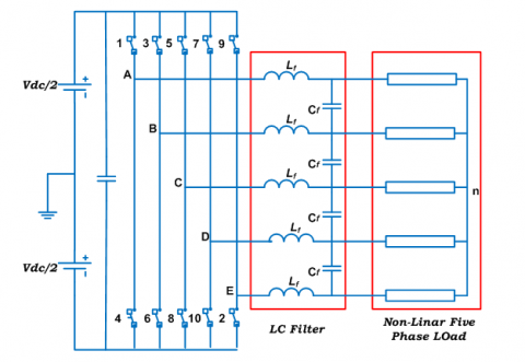
Figure 1 shows the circuit diagram of two-level five-phase voltage source inverter. The inverter input is connected with dc-link source and the output of inverter is connect to non-linear five-phase load through LC filter. Five-phase inverter consists of five legs having two semiconductor switches in each leg, i.e. IGBT, totaling ten switches. The operation of both switches on the same leg is complementary, to avoid the short-circuiting of the input DC source.
Figure 1. Circuit diagram of five phase VSI
Using the SVPWM scheme, a two-level voltage source inverter generates 2n space voltage vector, where n is the number of phases. Therefore, in a five-phase inverter, there will be 25 = 32 switching vectors with thirty active vectors and two zero vectors [3]. The five-phase input voltage equations are:
$v_{a}=\sqrt{2} \cos (\omega t)$
$v_{b}=\sqrt{2} \cos (\omega t-2 \pi / 5)$
$v_{c}=\sqrt{2} \cos (\omega t-4 \pi / 5)$ (1)
$v_{d}=\sqrt{2} \cos (\omega t+4 \pi / 5)$
$v_{e}=\sqrt{2} \cos (\omega t+2 \pi / 5)$
Since it is a five-phase system, all the vectors have to be represented in five axes, i.e. d-q, x-y and zero axis. The power invariant method will use to calculate the angle and magnitude of all vectors using a matrix.
$\mathrm{T}=\frac{2}{5}\left[\begin{array}{ccccc}1 & \cos (\pi / 5) & \cos (2 \pi / 5) & \cos (3 \pi / 5) & \cos (4 \pi / 5) \\ 0 & \sin (\pi / 5) & \sin (2 \pi / 5) & \sin (3 \pi / 5) & \sin (4 \pi / 5) \\ 1 & \cos (2 \pi / 5) & \cos (4 \pi / 5) & \cos (\pi / 5) & \cos (3 \pi / 5) \\ 0 & \sin (2 \pi / 5) & \sin (4 \pi / 5) & \sin (\pi / 5) & \sin (3 \pi / 5) \\ 1 & 1 & 1 & 1 & 1\end{array}\right]$ (2)
Space vector of phase voltages in d-q and x-y axis are defined, using power variant transformation, as:
$v_{d q}=\frac{2}{5}\left(v_{a}+a v_{b}+a^{2} v_{c}+a^{* 2} v_{d}+a^{*} v_{e}\right)$ (3a)
$v_{x y}=\frac{2}{5}\left(v_{a}+a^{2} v_{b}+a^{*} v_{c}+a v_{d}+a^{* 2} v_{e}\right)$ (3b)
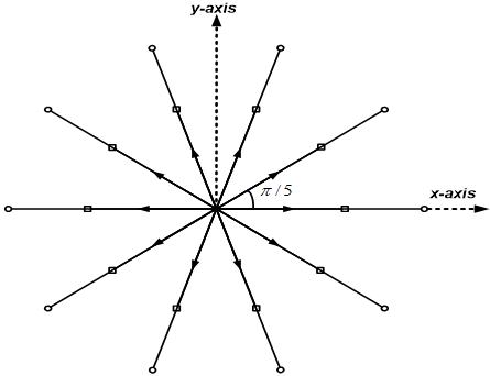
where, $\underline{a}=\exp (\mathrm{j} 2 \pi / 5)$ and * stands for a complex conjugate. The space vector is a complex quantity, which represents the five-phase balanced supply with a single complex variable. The voltage vectors in d-q axis are in Figure 2 and in x-y axis in Figure 3. It can be seen from Figure 2 that the outer decagon space vectors of the d-q plane map into the inner decagon of the x-y plane (Figure 3), the innermost decagon of d-q plane forms the outer decagon of the x-y plane, while the middle decagon space vectors map into the same region.
Figure 2. Space vector in d-q axis
Figure 3. Space vector in x-y Axis
All the thirty active vectors have divided in three groups according to their magnitude, i.e. large vectors, medium vectors and small vectors. The magnitudes are identified with indices l, m and s and are given as:
$v_{l}=(4 / 5) \cos (\pi / 5) \mathrm{V}_{\mathrm{dc}}$
$v_{m}=(2 / 5) \mathrm{V}_{\mathrm{dc}}$ (4)
$v_{s}=(4 / 5) \cos (2 \pi / 5) \mathrm{V}_{\mathrm{d} c}$
Two zero vectors are at the origin with zero magnitude. An ideal SVPWM should satisfy several requirements: (i) to keep the switching frequency constant, each switch can change state only twice in the switching-period (once ‘on’ to ‘off’ and once ‘off’ to ‘on’, or vice-versa), (ii) the RMS value of the fundamental phase voltage of the output must equal the RMS value of the reference space vector, (iii) the scheme must provide full utilisation of the available dc bus voltage, (iv) since the inverter is aimed to supplying the load with sinusoidal voltages, the low-order harmonic content needs to be minimised. There exist two conventional methods for realizing space vector PWM in a five-phase VSI: (a) using large vectors only which generates higher output, but the output is polluted with low-order harmonics, (b) using large and medium vectors which generate lower output, but a pure sinusoidal waveform.
The author has proposed PWM schemes for the five-phase dual VSI using only large vectors in this paper. Large vectors are in the outer-most decagon of space vectors in d-q plane. The input reference voltage vector is synthesised from two active neighbouring large vectors and zero vectors. Figure 4 is showing the positions of all the large vectors and zero vectors.
Figure 4. Space voltage vectors representation only large vectors
Figure 5. Principle of space vector time calculation for a five-phase VSI
The switching vector application time can be used to control the output voltage and frequency. Consider Figure 5, which shows the location of different available space vectors and the reference vector in the first sector to calculate the time of application of different vectors.
The times of active space vector application are from Figure 4 [4].
$t_{a}=\frac{\left|v_{s}^{*}\right| \sin \left(\frac{k \pi}{5}-\alpha\right)}{\left|v_{l}\right| \sin (\pi / 5)}$
$t_{b}=\frac{\left|v_{s}^{*}\right| \sin \left(\alpha-(k-1) \frac{\pi}{5}\right)}{\left|v_{l}\right| \sin (\pi / 5)}$ (5)
$t_{s}=t_{0}+t_{a}+t_{b}$
where, k is the sector number (k= 1,2,3.......10).
$v_{a l}=v_{b l}=v_{l}=(4 / 5) \cos (\pi / 5) \mathrm{V}_{\mathrm{dc}}$.
$v_{S}^{*}$= reference voltage vector.
ta = time of application of vector ‘a’.
tb = time of application of vector ‘b’.
ts = total switching period for one sector.
t0 = time of application of zero vectors.
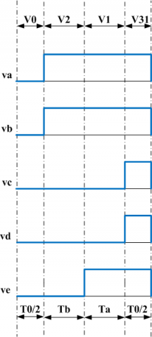
The sequence of vectors applied and corresponding switching pattern for sector 1 as per the conventional SVPWM is in Figure 6, where vectors v0 and v31 are zero vectors. The switching pattern is a mirror image for half of the switching time, i.e., if the total switching period for one cycle is Ts, then the switching pattern for Ts/2 is a mirror image for the other Ts/2 period.
Figure 6. Switching sequence for sector 1 using conventional SVPWM with only large vectors
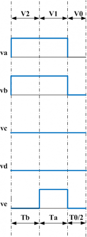
The proposed switching sequences for a five-phase inverter with different time distributions of active vectors (Ta and Tb) and zero vectors (T0) are in Figures 7 to 10. The active and zero vectors are placed and applied in such a way that only one transformation occurs during each sequence, which helps to reduce switching losses.
The switching sequence 1 (SS-1) in Figure 7 is just half of the pattern from the conventional pattern. During the sampling period each sector was divided into four parts for the switching period Ts in switching sequence 1. The switching period Ts = Ta+Tb+T0/2. The zero vector used in this scheme is v31.
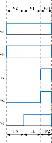
In switching sequence 2 (SS-2), each sector has divided into three segments during switching period Ts for the selected voltage vectors v2, v1 and v31. Figure 7 depicts the switching sequence 2, which only uses the zero vector once per switching cycle.
Figure 9 depicts the switching sequence 3 (SS-3) in which the sector is divided into three segments, but zero vector v0 is used this time. The switching series 4 (SS-4) is depicted in Figure 10. The sector has been divided into four segments, but this time no zero vector has been used; instead, only active vectors have been arranged in such a way that the switching process on sector 1 can be achieved.
Figure 7. Switching sequence-1
Figure 8. Switching sequence-2
Figure 9. Switching sequence-3
Figure 10. Switching sequence-4
The proposed switching sequences were simulated using Matlab/Simulink, and the results have presented for validation. The simulation parameters are 5 kHz inverter switching frequency, 50 Hz fundamental input reference frequency, and unity inverter dc-link voltages. The simulation results for the conventional switching sequence are in Figure 11.
Figure 11. Five phase filtered leg voltages using conventional switching scheme
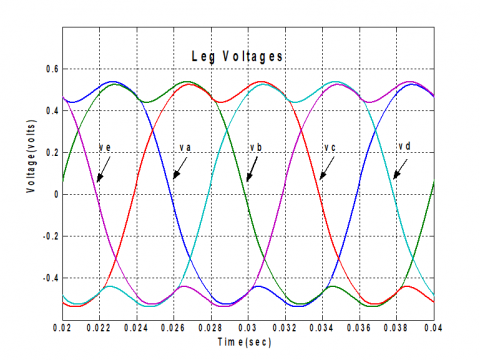
Figure 12. Filtered five phase leg voltages using proposed switching schemes
Figure 12 shows the simulation results for five-phase filtered leg voltages using the proposed schemes, which are identical to the conventional results, indicating that the finding is right. Simulation result shows that all the input phase voltages are 72° displaced from each other. The harmonic spectrum for phase ‘a' voltage for proposed switching sequences is shown in Figures 13 to 15.
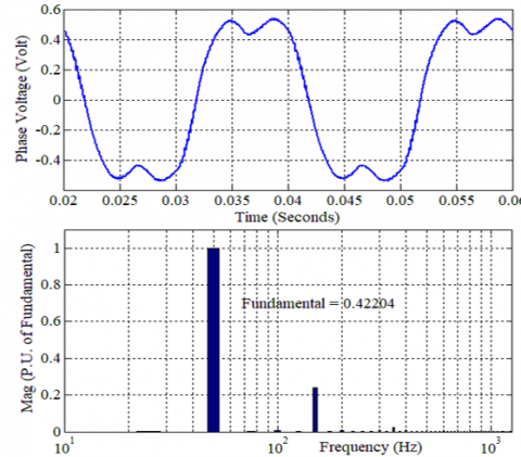
Figure 13. Harmonic spectrum for phase ‘a’ voltage (SS-1)
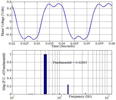
Figure 14. Harmonic spectrum for phase ‘a’ voltage (SS-2 &3)
Figure 15. Harmonic spectrum for phase ‘a’ voltage (SS-4)
Table 1. Comparison of all proposed schemes
|
Switching Sequence |
Fundamental Component (p.u.) |
THD (%) |
|
SS-1 |
0.422036 |
24.02 |
|
SS-2 & SS -3 |
0.422942 |
23.99% |
|
SS-4 |
0.428628 |
23.71% |
The performance of all of the SVPWM switching schemes discussed and simulated in this paper has been investigated, and a comparison of their fundamental components and % THD has been made based on the data obtained from simulation. A fast comparison of all proposed schemes is shown in the Table 1.
The fundamental component of all the schemes is nearly the same, but the %THD for SS-4 is the lowest of all the schemes.
This paper proposes voltage vector switching sequences based on the SVPWM scheme for performance evaluation of a two-level five-phase voltage source inverter. The switching pattern must be configured for quality control of the inverter system. Proposed switching schemes have simulated and the results shows that all of the switching schemes have approximately the same fundamental component magnitude. All of the schemes are easy to execute and dependable. Practical investigations may be used to verify the conclusions.
|
PWM |
Pulse width modulation |
|
SVPWM |
Space Vector pulse width modulation |
|
IGBT |
Insulated-gate bipolar transistor |
|
THD |
Total harmonic distortion |
[1] Van der Broek, H.W., Skudelny, H.C., Stanke, G.V. (1988). Analysis and realization of a pulse width modulator based on voltage space vectors. IEEE Transactions on Industry Applications, 24(1): 142-150. https://doi.org/10.1109/28.87265
[2] Schonung A., Stemmler, H. (1964). Static frequency changers with subharmoniccontrol in conjunction with reversible speed AC drives. Brown Boveri Rev., 51: 555-557.
[3] Iqbal, A., Levi, E. (2005). Space vector modulation schemes for a five phase voltage source inverter. European Conference on Power Electronics and Applications, Dresden, Germany, pp. 12. https://doi.org/10.1109/EPE.2005.219194
[4] Iqbal, A., Moinuddin, S., Khan M.R. (2006). Space vector model of a five-phase voltage source inverter. IEEE International Conference on Industrial Technology, Mumbai, India, pp. 488-493. https://doi.org/10.1109/ICIT.2006.372258
[5] Khan, M.A., Iqbal, A. (2007). Discontinuous space vector PWM techniques for a five-phase VSI with higher DC bus utilization. Indicon 2007 & 16 Annual Symposium of IEEE Bangalore section, Bangalore, pp. 6-8.
[6] Levi, E. (2008). Multiphase electric machines for variable-speed applications. IEEE Transactions on Industrial Electronics, 55(5): 1893-1909. https://doi.org/10.1109/TIE.2008.918488
[7] Holmes, D.G., Lipo, T.A. (2003). Pulse Width Modulation for Power Converters: Principles and Practice. John Wiley & Sons.
[8] Zulkifli, M.S.B., Munim, W.N.B.W.A., Haris H.C.M. (2012). Five phase space vector modulation voltage source inverter using large vector only. International Symposium on Computer Applications and Industrial Electronics (ISCAIE), Kota Kinabalu, Malaysia, pp. 5-9. https://doi.org/10.1109/ISCAIE.2012.6482057
[9] Chinmaya, K.A., Bhasker, M.U. (2014). Analysis of different space vector pulse width modulation techniques for five-phase inverters. Annual IEEE India Conference (INDICON), Pune, India, pp. 1-6. https://doi.org/10.1109/INDICON.2014.7030457
[10] Gupta, S.K., Khan, M.A. Iqbal, A., Husain, Z. (2012). Comparative analysis of pulse width modulation schemes for five phase voltage source inverter. Students Conference on Engineering and Systems, Allahabad, Uttar Pradesh, pp. 1-6. https://doi.org/10.1109/SCES.2012.6199036
[11] Bakhshai, A.T., Joos G., Jin H. (1997). Space vector PWM control of a split-phase induction machine using the vector classification technique. Proc. IEEE APEC, Atlanta, GA., pp. 802-808. https://doi.org/10.1109/APEC.1998.653990
[12] Kelly, J.W., Strangas, E.G., Miller, J.M. (2003). Multiphase space vector pulse width modulation. IEEE Trans. on Energy Conversion, 18(2): 259-264. https://doi.org/10.1109/TEC.2003.811725
[13] DeSilva, P.S.N., Fletcher, J.E., Williams, B.W. (2004). Development of space vector modulation strategies for five-phase voltage source inverters. Second IEE International Conference on Power Electronics, Machines and Drives, Edinburgh, UK, pp. 650-655. https://doi.org/10.1049/cp:20040365
[14] Zhao, Y., Lipo, T.A. (1995). Space vector PWM control of dual three-phase induction machine using vector space decomposition. IEEE Trans. on Industry Applications, 31(5): 1100-1109. https://doi.org/10.1109/28.464525
[15] Iqbal, A., Levi, E. (2006). Space vector PWM techniques for sinusoidal output voltage generation with a five-phase voltage source inverter. Electr. Power Component System, 34(2): 119-140. https://doi.org/10.1080/15325000500244427
[16] Duran, M.J., Levi, E. (2006). Multi-dimensional approach to multi-phase space vector pulse width modulation. IECON 2006 - 32nd Annual Conference on IEEE Industrial Electronics, Paris, France, pp. 2103-2108. https://doi.org/10.1109/IECON.2006.347436
[17] Dujic, D., Iqbal, A., Levi E. (2007). A space vector PWM technique for symmetrical six-phase voltage source inverters. European Power Electronics and Drives, 17(1): 24-32. https://doi.org/10.1080/09398368.2007.11463639
[18] Kestelyn, X., Semail, E., Hautier J.P. (2004). Multi-phase system supplied by SVM VSI: A new fast algorithm to compute duty cycles. EPE Journal, 14(3): 25-31. https://doi.org/10.1080/09398368.2004.11463562
[19] Kianinezhad, R., Nahid, B., Betin, F., Capolino G.A. (2005). Multivector SVM: A new approach to space vector modulation for six-phase induction machines. Proc. IEEE IECON, Raleigh, NC, pp. 1359-1364. https://doi.org/10.1109/IECON.2005.1569103
[20] Xue, S., Wen X. (2005). Simulation analysis of two novel multiphase SVPWM strategies. Proc. IEEE ICIT, Hong Kong, pp. 1401-1406. https://doi.org/10.1109/ICIT.2005.1600843
[21] Ryu, H.M., Kim, J.H., Sul S.K. (2004). Analysis of multiphase space vector pulse-width modulation based on multiple d-q spaces concept. IEEE Trans. Power Electron, 20(6): 1364-1371.https://doi.org/10.1109/TPEL.2005.857551
[22] Xue, S., Wen, X.H., Feng, Z. (2006). A novel multi-dimensional SVPWM strategy of multiphase motor drives. Proc. EPE-PEMC, Portoroz, Slovenia, pp. 931-935. https://doi.org/10.1109/EPEPEMC.2006.4778519
[23] Lavanya, M., Jyothi, B. (2016). Performance analysis of 5-phase multi-level inverter using carrier based pwm technique. International Journal of Applied Power Engineering (IJAPE), 5(3): 151-158. https://doi.org/10.11591/ ijape.v5.i3
[24] Jyothi, B., Rao, M.V.G. (2017). Performance analysis of 3-level 5-phase multilevel inverter topologies. International Journal of Electrical and Computer Engineering, 7(4): 1696-1705. https://doi.org/10.11591/ijece.v7i4
[25] Lihitkar, S., Rangari, S. (2018). Comparative study of IPD and POD for three level five phase inverter. 2018 International Conference on Smart Electric Drives and Power System (ICSEDPS), Nagpur,India, pp. 313-316. https://doi.org/10.1109/ICSEDPS.2018.8536047
[26] Raja, D., Ravi, G. (2019). New switch ladder topology for five phase multilevel inverter fed five phase induction motor. International Journal of Power Systems, 4:64-69.
[27] Sajitha, M., Ramchand, R. (2019). Space vector PWM scheme for three phase three level t-type NPC inverter. 2019 2nd International Conference on Intelligent Computing, Instrumentation and Control Technologies (ICICICT). Kannur, India. https://doi.org/10.1109/ICICICT46008. 2019. 8993215.
[28] Ramasamy, P., Krishnasamy, V. (2020). Minimization of common-mode voltage for five-phase three-level NPC inverter using SVPWM strategy. Iranian Journal of Science and Technology, Transactions of Electrical Engineering, 44: 1221-123.https://doi.org/10.1007/s40998-019-00304-5
[29] Usha, S., Geetha, A., Thentral, T.M.T., Subramani, C., Venkatesan, M. (2020). Mitigation of common mode voltage in five phase multilevel inverter. Proceedings Materialstoday. https://doi.org/10.1016/j.matpr.2020.08.625