Divya Manukonda* | Srinivasa Rao Gorantla
OPEN ACCESS
The utilization of renewable energy sources has become attractive due to their numerous advantages. This paper presents the design of a new affordable bladeless standalone hybrid system utilizing wind energy and solar energy. The proposed new affordable bladeless standalone hybrid system is an integration of bladeless wind turbine and solar panel. This paper consists of mathematical modeling of bladeless wind turbine, solar panel and also involves comparison of bladeless hybrid system with the existing solar wind hybrid system and the comparison is performed in terms of voltage, current, power that are produced from the both the hybrid systems. The bladeless hybrid system is designed and all the results are verified using Matlab Simulink
bladeless standalone wind hybrid system, conventional hybrid system, bladeless wind turbine, vortex vibrations
Now a days the power consumption is more compared to the available power and the pollution is also increasing. So, one of the solutions to overcome the above mentioned two disadvantages is producing the power with the renewable energy sources which are unlimited and non-pollutant. Among the available renewable energy sources, wind and solar sources [1] have number of advantages like unlimited, clean.
Using wind as a source there have been number of wind turbines like Horizontal axis wind turbine, vertical axis wind turbine, Darrius wind turbine but the disadvantages with these wind turbines is high investment, noise, fatal to birds, higher wind speed requirement and no availability of wind all the times. So solar can be used for power generation but even it has disadvantage that it is not available at night times and no power generation. So, using of single renewable source at a time may not meet the load requirement and so by combining these sources [2, 3] they can be effectively used which leads to hybrid system.
Standalone Hybrid power generation system [4-6] produces electrical energy with the use of more than one source and if one is not available another source can be used +for running the load. Standalone Solar wind hybrid power generation system uses solar and wind as sources, but the conventional wind turbine has disadvantages like higher wind speed requirement, high investment, fatal to birds, noise.
Bladeless wind turbine is an alternative solution of generating power with wind and getting rid of the disadvantages of conventional horizontal axis wind turbine and the basic principle behind the bladeless turbine is vortex induced vibrations [4]. Vortex vibrations are the vibrations that are induced with in a structure when wind is passed through it and producing oscillatory motion. These oscillations can be converted into electrical energy using devices like piezoelectric cells, crank and shaft mechanism, linear alternator but producing low energy, high maintenance and so transducer [7] can be opted for energy conversion. But the produced energy may not be sufficient for usage and so high gain step up DC-DC converter can be used for boosting the voltage up to the required value instead of using conventional boost converter. To reduce the filter requirements and to reduce total harmonic distortion of output energy three level inverter [8] can be used instead of conventional two-level inverter.
The paper is organized as follows; the first section of the paper is dealing with the comparision of proposed bladeless hybrid system and conventional hybrid system, the second section of the paper is dealing with the mathematical modelling of proposed bladeless hybrid system and the third part discusses with controller for wind turbine and the fourth part deals with the software realization of proposed system, result and discussion of the proposed system and the fifth part deals with the conclusion.
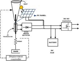
The proposed bladeless hybrid system which is shown in below Figure 1 works on the principle of vortex induced vibrations.
It is an integrated system of bladeless wind turbine and solar panel in which the bladeless wind turbine consists of a tapered cylindrical mast made up of fiber glass or carbon fiber and a rod is pivoted into the mast which provides support to the mast. When wind passes over the mast, vortex vibrations are induced around the mast in which alternating forces are produced and the mast starts displacing. To make the mast to oscillate with continuous to and pro motions and to increase the oscillations of the mast, a spring has been attached at the bottom the turbine.
These oscillations are converted to electrical energy by using electro-acoustic transducer and then to DC power by diode bride rectifier. A solar panel is attached to the bladeless turbine leads to bladeless hybrid system. This DC power can be stored in a battery which can be used if both the sources are not available. But the total DC is not sufficient to meet the AC loads requirement and so a high gain step up converter is used to boost the DC voltage and the boosted DC output is fed to the three level inverter for residential and commercial applications. This bladeless wind turbine has no blades and so no noise, no fatal to the birds and also it consists of less number of parts and so requires less space.
Figure 1. Proposed bladeless wind solar hybrid system
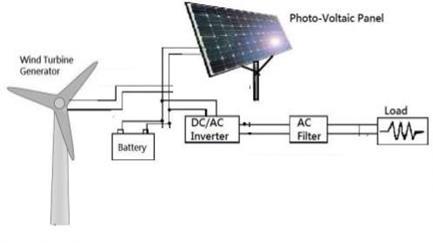
Figure 2. Conventional bladeless wind solar hybrid system
Table 1. Comparison of conventional hybrid system and bladeless hybrid system
|
|
Conventional Hybrid System |
Bladeless Hybrid System |
|
Principle |
Rotatory |
Oscillatory |
|
Type of Turbine |
Tapered Cylindrical Mast |
Rotor with Blades |
|
Output of The Turbine |
Displacement |
Mechanical Energy |
|
Energy Conversion Device |
Transducer |
Alternator |
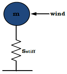
Bladeless wind turbine is basically a system consisting of mass $m$ and spring having stiffness of $S_{\text {stiff}}$ can be shown with mass spring system which is shown in below Figure 3.
Figure 3. Mass spring system
The following are the designing equations [9, 10] involved for the spring mass system.
A tapered cylindrical structured mast made of fiber whose mass is given as
$m=\frac{\pi}{3} \rho L\left(D^{2} / 4\right)$ (1)
where $L$ is length of the mast, $\rho$ is density of $\operatorname{arr}, D$ is the diameter of mast.
The flow of wind over the mast induces vortex vibrations which can be characterized by the Reynolds number and strouhal number given as
$R_{n}=\frac{U_{W} D}{\mu}$ (2)
where $U_{W}$ is velocity of wind, $\mu$ is kinematic viscosity. For the Reynolds number vs strouhal number data strouhal number, $S_{t r n}=0.2$ for considered wind speed.
These vortex vibrations can be determined with a frequency called strouhal frequency $f_{s t r}$ [9] can be given as
$f_{\text {str}}=\frac{S_{\text {trn}} U_{W}}{D}$ (3)
A spring used for increasing oscillations of the mast with spring stiffness [9] given as
$S_{\text {stiff }}=m w_{\text {nat }}^{2}$ (4)
where $W_{n a t}$ is natural frequency of the mass spring system.
The resultant of the vortex vibrations produces alternating lift forces $F_{\text {lift}}$ [9] can be given as
$F_{l i f t}=\frac{1}{2} \rho U_{W}^{2} A_{m} L_{c o e f f}$ (5)
where $A_{m}$ is area of the mast, $L_{\text {coeff }}$ is coefficient of lift force.
The resulting displacement $Z$ of the mast [9] can be given as
$\ddot{z}=\frac{F_{\text {lift}}}{m}-\frac{S_{\text {stiff}} Z}{m}$ (6)
3.2 Solar panel
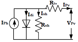
A solar panel consists of solar modules which intern contains solar cells. A solar cell basically consists of a p-n junction diode and internal resistance which is shown in below Figure 4.
Figure 4. Equivalent circuit of solar cell
When sun rays fall on the solar cell, the total current that is generated is $I_{p h}$ .
The following are the designing equations [1-5] involved for the solar cell.
The diode current can be given as
$I_{d i}=I_{o}\left(e^{\frac{q V_{P V}}{n K T}}-1\right)$ (7)
The current through the shunt resistance can be given as
$I_{s h}=\left(\frac{V_{P V}+I_{s e} R_{s e}}{R_{s h}}\right)$ (8)
The current collected at the output of the solar cell can be given as
$I_{P V}=I_{p h}-I_{d i}-I_{s h}$ (9)
The voltage across the solar cell can be given as
$V_{P V}=\frac{K T}{q}\left[\ln \left(1-\frac{\left(I_{P V}-I_{p h}\right)}{I_{o}}\right)\right]$ (10)
where $K$ is Boltzmann constant, $T$ is the temperature, $q$ is charge of electron.
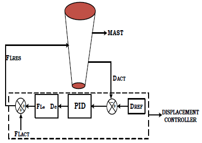
The resultant displacement of the mast is not constant which may vary with environmental conditions and load conditions and so to control the alternating displacement PID based displacement controller has been designed whose block diagram is shown in below Figure 5. The displacement of the bluff body is measured and it is compared with the reference value of the displacement and the error is fed to the PID controller which is processed and with the processed displacement error, the error lift force is produced and the actual lift force is added with this error lift force and the resultant lift force is fed to the mast and there by displacement can be corrected.
Figure 5. Block diagram of displacement controller for mast
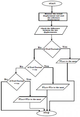
Figure 6. Flow chart of displacement controller for mast
The operation of the above displacement controller can be explained with the flow chart given below.
If the difference in the displacement is zero, the error lift force is zero and actual lift force is fed to the mast.
If the difference in the displacement is positive which means actual displacement is less than the reference displacement, the error lift force produced is positive and resultant lift force which is the sum of actual lift force and error lift force is fed to the mast, thereby increase in the net lift force increases the displacement until it attains reference displacement.
If the difference in the displacement is negative which means actual displacement is greater than the reference displacement, the error lift force produced is negative and resultant lift force which is the difference of actual lift force and error lift force is fed to the mast, thereby decrease in the net lift force decreases the displacement until it attains reference displacement.
The bladeless hybrid system is an integration of bladeless wind turbine and solar panel. When wind passes over the mast due to vortex action displacement whose value is 0.22m is the resultant motion for wind speed U=2m/s, which is shown in below Figure 7.
Figure 7. Displacement of mast
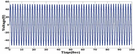
The displacement has been converted into AC power using AC transducer whose value is 52VAC shown in below Figure 8.
Figure 8. Output voltage of an AC transducer
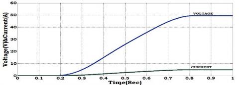
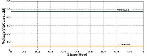
The AC electrical power has been converted into DC power using diode bridge rectifier whose voltage value is 50VDC, current value is 4.7A and is shown in below Figure 9.
Figure 9. Voltage and current of diode bridge rectifier
A solar panel of 48V DC has been designed and its output voltage and current whose values are 48V DC and 4.8A is shown in below Figure 10.
Figure 10. Voltage and current of solar panel
The voltage and current obtained from the bladeless wind turbine, solar panel are integrated and fed to high gain step up DC-DC converter and the voltage, current & power which are boosted which is shown in below Figure 11.
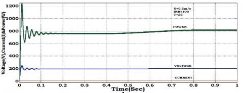
The hybrid system has been simulated for different wind speed conditions U=0.5m/s, U=1m/s, U=1.5m/s, U=2m/s and the four outputs are shown inbelow Figures 12,13 & 14.
Figure 11. Voltage, current and power of hybrid system for U=0.5m/s
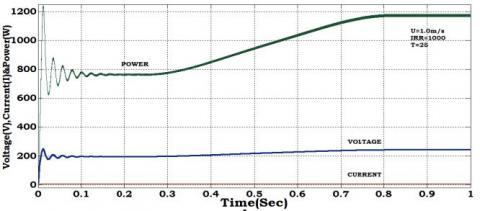
Figure 12. Voltage, current and power of hybrid system for U=1m/s
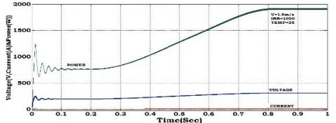
Figure 13. Voltage, current and power of hybrid system for U=1.5m/s
Figure 14. Voltage, current and power of hybrid system for U=2m/s
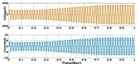
The output from the DC-DC converter is fed to three level inverter and the resultant voltage ,current whose values are 400VAC, 8A are shown in below Figure 15.
Figure 15. Voltage, current and power of three level inverter
Table 2. Proposed hybrid system
|
|
Voltage |
Current |
power |
|
Vortex turbine wind speed(m/s)-2m/s |
50V |
5A |
250W |
|
PVpanel(irr,temp)-1000 $\mathrm{W} / \mathrm{m}^{2}, 25^{\circ} \mathrm{C}$ |
49V |
5A |
240W |
|
DC-DC converter |
400V |
8A |
3200W |
|
Three level inverter |
400V |
8A |
3200W |
Table 3. Proposed hybrid system vs conventional hybrid system
|
Wind speed(m/s)-2m/s Irradiance-1000W/ $m^{2}$ Temperature- $25^{0} C$ |
Proposed hybrid system |
Conventional hybrid system |
|
Voltage |
400V |
150V |
|
Current |
8A |
2A |
|
Power |
3200W |
300W |
The proposed hybrid system and the conventional hybrid system are simulated using MATLAB Simulink and the voltage, current & power are shown in above Table 3.
Table 4. Specifications of bladeless hybrid system
|
S.No. |
Parameter |
Value |
|
1. |
Wind speed,U |
2m/s |
|
2. |
Length of the mast,L |
1m |
|
3. |
Diameter of the mast,D |
150mm |
|
4. |
Transducer input voltage |
5Vrms |
|
5. |
Solar panel |
48V |
|
6. |
Duty cycle of DC-DC converter |
0.6 |
|
7. |
Reynolds number |
22860 |
The above Table 4 shows the specifications of the bladeless hybrid system.
A new affordable standalone bladeless wind solar hybrid system has been designed and its analysis has been done. A comparison has been performed between the designed bladeless wind solar hybrid system and the conventional hybrid system for different wind speed conditions in terms of voltage, current and power. From the comparison it is concluded that designed bladeless hybrid system provides higher power when compared to the conventional hybrid system for lower wind speeds.
[1] Praveen, S., Shimi, S.L., Lini, M. (2016). Design and implementation of MPPT technique applied to solar wind hybrid system. International Journal of Advanced Research in Computer and Communication Engineering, 5(7): 604-609. http://doi.org/10.17148/IJARCCE.2016.57120
[2] Gadad, S.A. (2016). Mathematical modeling of hybrid wind and photovoltaic energy system using Matlab/Simulink. International Journal for Innovative Research in Science & Technology, 3(3): 85-92.
[3] Nnadi, D.B.N., Odeh, C.I., Omeje, C. (2014). Use of hybrid solar-wind energy generation for remote area electrification in South-Eastern Nigeria. Journal of Energy in Southern Africa, 25(2): 61-69. http://doi.org/10.17159/2413-3051/2014/v25i2a2670
[4] Bogaraj, T., Kanakaraj, J., Chelladurai, J. (2015). Modeling and simulation of stand-alone hybrid power system with fuzzy MPPT for remote load application. Archives of Electrical Engineering, 64(2): 487-504. https://doi.org/10.2478/aee-2015-0037
[5] Anjali, R., Mohammad, I. (2015). Implementation of a Wind/PV hybrid system using MATLAB/Simulink. International Journal of Advanced Research in Electrical, Electronics and Instrumentation Engineering, 4(7): 5941-5948. http://doi.org/10.15662/ijareeie.2015.0407019
[6] Manfrida, G., Rinchi, M., Soldi, G. (2016). Dynamic model of a vortex-induced energy converter. In Journal of Energy Resources Technology, 138(6). http://doi.org/10.1115/1.4033587
[7] Baidwan, K.I.S., Kumar, C.R.S. (2015). Design of linear variable differential transformer (LVDT) based displacement sensor with wider linear range characteristics. International Journal of Science & Technoledge, 3(4): 74-79.
[8] Murugesan, M., Pari, R., Sivakumar, R., Sivaranjani, S. (2016). Different types of multilevel inverter topologies–a technical review. International Journal of Advanced Engineering Technology, 7(1): 149-155.
[9] Mohammed, J.M., Intan, Z., Mat, D. (2014). Active vortex induced vibration controller and neuro identification for marine risers. Journal of Theoretical and Applied Information Technology, 70(1): 153-163.
[10] Zhang, M.M., Cheng, L., Zhou, Y. (2004). Closed-loop controlled vortex shedding and vibration of a flexibly supported square cylinder under different schemes. In Physics of Fluids, 16(5). https://doi.org/10.1063/1.1687413