Rahma Gannoun | Walid Hassen | Alberto T. Pérez | Mohammed Naceur Borjini*
OPEN ACCESS
In this article, a numerical study was conducted to analyze the effect of electro-convection and electro-thermo-convection in a solar chimney geometry subjected to the simultaneous action of an electric field and a thermal gradient (in the case of electro-thermo-convection). The full set of equations is solved using the finite element software COMSOL Multiphysics. The effects of thermal and electric Rayleigh numbers on charge density distribution, fluid flow and temperature distribution are analyzed. Also the impact of different chimney collector widths is studied in order to determine the optimum width allowing achieving the maximum fluid velocity. It was shown that using a smaller chimney collector width is more convenient in order to increase the fluid flow velocity. In addition, an evaluation of the heat transfer enhancement was made by observing the evolution of heat flow at the exit of the chimney tower as a function of both, the electric and thermal Rayleigh numbers. It was found that the heat transfer enhancement reaches more than 90 % when thermal Rayleigh rises from 5000 to 20000. Finally, the effect of Prandtl number was investigated.
charge injection, electro-convection, electro-thermo-convection, solar chimney geometry, numerical method
There is a growing awareness that alternative energy resources may play an important role in the production of electricity in many parts of the world. Solar energy is an inexhaustible, non-polluting resource and important to meet the current and future energy needs of humans. There are several ways to exploit solar energy: The solar chimney (SC) is one of these ways. In fact, it is an electricity production tool, which increases the internal energy of fluid flowing through the system using solar radiation.
Pasumarthi and Sheriff [1-2] developed a mathematical model to predict the performance of solar chimney and studied also the effect of the geometrical parameters and the ambient conditions. Ming et al. [3] carried out a steady state numerical simulation based on two dimensional assumptions in order to optimize the dimensions of the chimney. Zhou et al. [4] conducted a research to evaluate the optimal height of the prototype located in Manzanares (Spain). They revealed that the optimal chimney height is 615 m. Using the commercial code “Fluent”, Hu et al. [5] analyzed the divergent solar chimney. Their results showed that the performance of the SC is affected by all the studied parameters (the chimney exit over entrance and the divergent angle of the chimney). Nia and Ghazikhani [6] using a passive flow control method, presented a numerical investigation on the heat transfer enhancement in solar chimney. They had shown that three main mechanisms: flow pattern guidance, agitation in thermal boundary layer, thickening and the emergence of vorticities, allow improving heat transfer.
In fact, all habitual solar chimneys have some deficiencies. Among these deficiencies, the energy conversion process is affected by the limited free convection heat transfer. However, there are some active techniques that would overcome this problem. Electro-thermo-hydrodynamics is one of these techniques. This method is based on the interaction between electric field, flow and temperature. Moghanlou [7] presented an experimental study on EHD induced heat transfer in a mini channel. Lakeh [8] has conducted a computational and experimental approach to study heat transfer in parallel plate configuration using an electrically-induced secondary flow field. Nourdanesh and Esmaeilzadeh [9] studied experimentally EHD pumping for different temperatures and film thickness. They showed that electric power consumption is independent of the temperature, and they confirmed the direct relationship between the film thickness and the applied voltage. Hassen et al. [10] studied the effect of the partial electric charge injection on heat transfer and on the flow structure in a differentially heated square enclosure. Mestiri et al. [11] have conducted an experimental study with two electrodes at the surface of a printed flat plate and a NACA0015 aircraft wing profile and they presented a parametric study of the corona discharge. Yabe et al. [12] proved that the corona wind velocity increases with the electrical current. Gannoun et al. [13] analyzed the mechanism of natural convection in horizontal channel incorporating EHD effects, for different electrodes arrangement. They concluded that the electrodes’ configuration impacts considerably on the heat transfer and an optimization of the positioning of the electrodes was achieved. Heat transfer enhancement was investigated by Velkoff and Godfrey when applying a corona discharge to air flow on a flat plate [14]. In another study, Bushnel [15] employed also corona wind for different velocities in order to decrease the drag force on a flat plate collector.
Using an EHD technique, Kasayapanand [16] investigated the heat transfer in an inclined solar chimney. He observed growing flow and heat transfer for low Rayleigh number and revealed that the optimum angle to achieve the maximum heat transfer was 60°. Nasirivatan found out the enhancement of heat transfer in the collector of the SC by applying an electric field [18]. Ghalamchi [19] implemented an EHD system in the collector part of the SC and investigated three different electrode layouts: parallel, symmetric and radial. His experimental work showed that the performance of SC was increased particularly by the parallel array of electrodes with 6 electrodes having 3 cm spacing between them.
To our knowledge, none of the above cited works has treated numerically the effect of electro-thermo-convection on fluid flow and on heat transfer in the geometry of solar chimneys, which represents the main objective of this paper. In a first stage in this article we will discuss charge density distribution and the flow structure for the purely electrconvective case, where the convection is induced by charge injection in a dielectric fluid. Then thermo-electroconvection will be investigated.
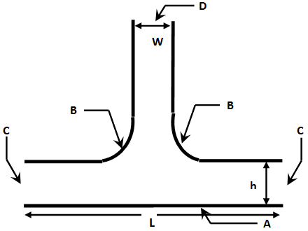
We consider a dielectric fluid layer flowing in solar chimney geometry.
The boundary conditions are similar to the real conditions of the solar chimney. The entries of the collector and the chimney exit are open. The emitting electrodes are also located at the inputs of the collector, while the receiving electrode has been placed at the exit of the tower which is designed to absorb the injected ions.
We applied the non-slip condition everywhere, except at the outlet and at the chimney entrances (Figure 1). For the study of electro-thermo-convection we impose a constant temperature at the bottom wall and constant lower temperature at the opposite walls and the vertical walls of the chimney.
Figure 1. The physical model
The problem is formulated considering the usual hypotheses of Newtonian and incompressible fluid of kinematic viscosity “ν”, density “ρ”, permittivity “ε” and thermal diffusivity “a”.
We assume that charge is injected at the emitting electrodes, and this injection is assumed to be ‘homogeneous’ and ‘autonomous’. The mobility of the ions is denoted by “K”. As it is usually done in electroconvection due to injection, Joule heating is neglected. Finally, we consider the Boussinesq approximation.
The whole set of equations expressing the conservation of mass and momentum (the Navier-Stokes equations) including electrical forces, energy conservation, charge density conservation, the Gauss law and the definition of the electric field via the electric potential V, takes the dimensionless form:
$\nabla .\vec{u}=0$ (1)
$\frac{\partial \vec{u}}{\partial t}+\left( \vec{u}.\nabla \right)\vec{u}=-\nabla \tilde{p}+\frac{{{M}^{2}}}{T}\Delta \vec{u}+{{M}^{2}}q\vec{E}$ (2)
$\frac{\partial q}{\partial t}+\nabla \cdot(q(\vec{u}+\vec{E}))=0$ (3)
$\Delta V=-q$ (4)
$\vec{E}=-\nabla V$ (5)
For the study of the simultaneous action of electric and thermal fields, the equations 2 and 3 take respectively the form:
$\frac{\partial \vec{u}}{\partial t}+\left( \vec{u}.\nabla \right)\vec{u}=-\nabla \tilde{p}+\Delta \vec{u}+RTCq\vec{E}+\frac{Ra}{\Pr }\theta \vec{e}y$ With $R=\frac{T}{{{M}^{2}}}$ (6)
$\frac{\partial q}{\partial t}+\nabla .\left( q\left( \vec{u}+R\vec{E} \right) \right)=0$ (7)
And we add the energy conservation equation:
$\frac{\partial \theta }{\partial t}+\vec{u}.\nabla \theta =\frac{1}{\Pr }\Delta \theta $ (8)
where we have introduced the following dimensionless scales: The applied voltage ∆V=V0-V1 for the electric potential, ∆V/L for the electric field, q0 for the charge density, ε0K∆2/L3 for the current density, V/L for the velocity, P0v2/L2 for the pressure, L2/v for the time and θ/(θ0-θ1) for the temperature.
The above set of coupled equations is solved numerically using the finite element software COMSOL Multiphysics [20-21].
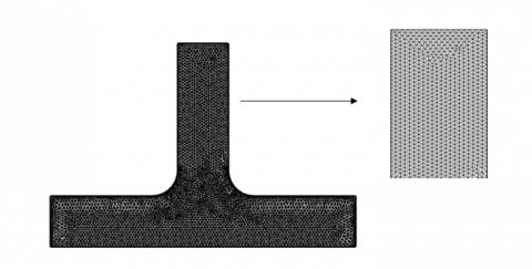
Figure 2 displays the computational mesh. The mesh is extremely fine and consists of 8343 elements. Grid dependence tests have been realized until successive refinement of the grid results in insignificant modification of the solution.
Figure 2. Computational mesh
Table 1. Boundary conditions
|
Boundary conditions |
Details |
|
|
A |
Hot wall |
$u=0 ; \theta=1 ; \frac{\partial q}{\partial y}=\frac{\partial v}{\partial y}=0$ |
|
B |
Cold wall |
$u=0 ; \theta=0 ; \frac{\partial q}{\partial n}=\frac{\partial v}{\partial n}=0$ |
|
C |
chimney inlet equipped with emitter electrode |
$u=0 ; \cdot \theta=1 ; \frac{\partial q}{\partial y}=\frac{\partial v}{\partial y}=0$ |
|
D |
chimney outlet equipped with collector electrode |
$\frac{\partial u}{\partial y}=0 ; \frac{\partial \theta}{\partial y}=0 ; q=v=0$ |
3.1 Pure electroconvection
3.1.1 Charge density distribution
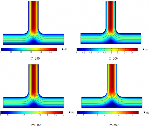
Figure 3 shows the distribution of the charge density for different electric Rayleigh numbers in the pure electroconvective case. The charges are beginning migration from the emitting electrodes symmetrically. The charges density is decreasing across the SC geometry. For T=200 and T=500, all the median region of the geometry remains void of charges.
Figure 3. Isocontours of the electric charge density for different electric Rayleigh numbers (pure electroconvection, C=1, M=10)
When T is increased, the charges invade gradually the entire geometry, then for T=2500, there is higher charge accumulation and the two charges compartments merge total.
3.1.2 Flow structure
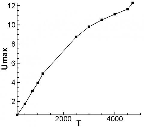
The velocity profile is always independent of the value of the electric Rayleigh number; however the maximum velocity increases progressively when the electric Rayleigh number is increased further. In fact, we note an increase exceeding 1000 % from T=200 to T=2500 (Figure 4), this increase reaches even 2000 % when T=4500 (Figure 5). We realize then a considerable improvement of the fluid flow. We also notice that the flow reaches its maximum velocity always in the chimney tower.
Figure 4. Flow structure for different electric Rayleigh numbers (pure electroconvection)
Figure 5. Maximum velocity versus electric Rayleigh number for C=1, M=10
3.2 Electrother moconvection
3.2.1 Charge density distribution
Figure 6. Isocontours of the electric charge density for different electrical Rayleigh number (Ra=10000, C=1, M=10 and Pr=10)
Figure 6 shows the distribution of the charge density for different electric Rayleigh values for combined electrother moconvection. We notice that the charges have preserved their symmetrical migration from the emitting electrodes. Unlike the purely electro convective case, even for low values of electric Rayleigh, the charges invade the entire geometry thanks to the cooperation of thermal and electric forces. As they progress through the chimney, the density of these electrical charges decreases and the charges are divided into two compartments. However, when T increases the charge dissemination is accelerated. The collector median region void of charges becomes narrower. For T=1200 the concentration of electrical charges is much higher and the two charged compartments tend to merge.
3.2.2 Flow structure
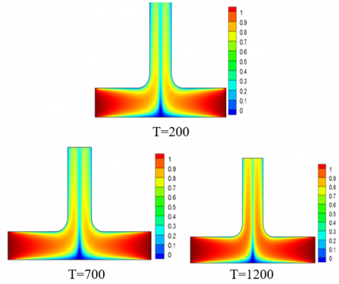
Figure 7 illustrates the streamlines for Ra=10000, C=1, M=10 and Pr=10 at different Rayleigh numbers. Due to the combined effect of thermal and electrical forces, it can be noted that the distribution of the velocity field reaches its maximum at the entrance of the tower. The velocity profile and flow structure always remain independent of the value of T, except some distortions of horizontal streamlines for T=200. However, the intensity of the maximum velocity increases with the electric Rayleigh number. Indeed, an increase of more than 10 times is recorded for T ranging from 200 to 1200.
Figure 7. Representation of stream lines for different electric Rayleigh numbers (Ra=10000, C=1, M=10 and Pr=10)
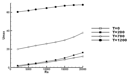
Figure 8. Maximum velocity versus thermal Rayleigh number for C=1, M=10, Pr=10 and for several values of the electric Rayleigh number
Figure 8 shows the maximum velocity versus thermal Rayleigh number for C=1, M=10, Pr=10 and for several values of the electric Rayleigh number. It is clear that the maximum velocity is an increasing function of the electric Rayleigh number. Indeed, for Ra=20000 an enhancement between 33 % and 460 % is recorded compared to the case of pure natural convection. This intensification was quite predictable since the applied electrical forces create additional movements in the fluid flow. A similar trend has been reported for other geometries [22, 23]. It can also be seen that from T=1200, the increase in the thermal Rayleigh number no longer affects the maximum speed, this is also have been confirmed in literature [24]. This means that the movement is entirely controlled and dominated by electrical forces, so the impact of thermal forces is negligible.
3.2.3 Temperature distribution and heat transfer
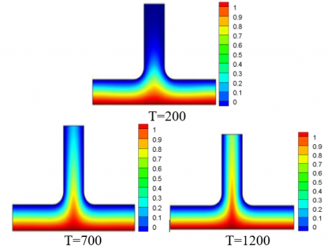
Figure 9 represents the isothermal lines for Ra=10000, C=1, M=10 and Pr=10 for different electric Rayleigh numbers. A symmetric profile is observed for all values of electric Rayleigh number. For T=200 a vertical stratification on the inlet channel takes place. The hot fluid layers cannot reach the tower outlet. In this case almost the entire tower remains at the cold temperature. By increasing T to 700 and then to 1200, a strong penetration of the hot layers of fluid occurs throughout the chimney tower. Despite the intensity of the electric field applied, the stratification at the channel inlet persists.
Figure 9. Representation of isotherms for Ra=10000, C=1, M=10, Pr=10 and for different electric Rayleigh number
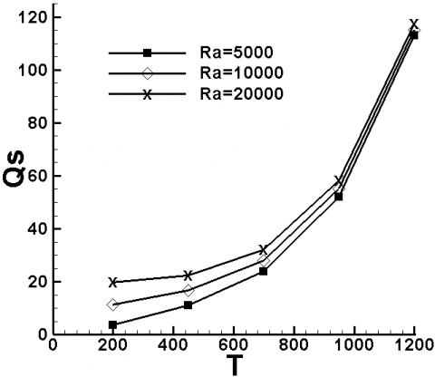
Figure 10. Convective heat flow at the exit of the chimney tower versus electrical Rayleigh number for C=1, M= 10, Pr=10 and for different thermal Rayleigh
Figure 10 displays the convective heat flow at the outlet of the chimney tower versus electric Rayleigh number for C=1, M= 10 and Pr=10 for different thermal Rayleigh numbers. Obviously the convective transfer increases with the thermal and electric forces as confirmed in this figure. We noted an improvement in thermal transfer that exceeds 1000% when T varies from 200 to 1200. This enhancement exceeds 90% when Ra rises from 5000 to 20000. From T=1000 the flow regime is electrically dominated. In this case, the electrical forces control the thermal transfer which becomes almost insensitive to thermal Rayleigh number.
3.2.4 Effect of Prandtl number
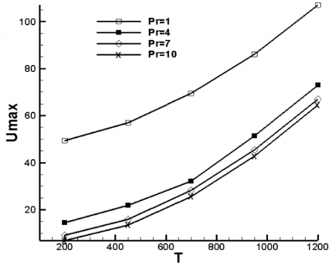
Figure 11 shows the evolution of the velocity magnitude versus the electric Raleigh number for different values of Pr. It is noted that the maximum velocity values are obtained for the lower values of Pr. We note that for Pr≥4, the values of the maximum speed are getting closer, whereas for Pr=1 a sudden increase in the maximum fluid velocity is observed. In fact, for this case, there is a dominance of advection over conduction that is occurring with dominance of inertial forces over viscous forces.
Figure 11. Maximum velocity versus electric Rayleigh number for C = 1, M= 10, Ra=1000 and for different values of the Prandtl number
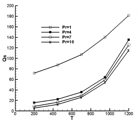
Figure 12. Convective heat flow at the exit of the chimney tower versus electric Rayleigh number for different Prandtl numbers
The similarity between the velocity magnitude profile and the total heat flux profile versus T (Figure 12) can be easily remarked. This result was expected because a higher velocity magnitude produces a higher heat flux. This is specifically noted in the chimney outlet due to the fact that the velocity is reaching its maximum in the entire chimney tower (as shown in Figure 7). On the other hand, the considerable increase of total heat flux for higher applied voltage, and consequently higher electric Rayleigh numbers is confirmed. It is to note that the relative increase of maximum velocity and heat transfer is lower for Pr=1 (air) than for liquid (Pr=10).
3.2.5 Geometric effects
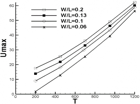
Figure 13 indicates the variation of the maximum velocity versus electric Rayleigh number for C=1, M=10, Pr=10 and for different collector widths. The aspect ratio h/L is equal to 0.2. Here, contrary to what we expected, the increase in the width of the solar chimney does not lead to an increase in the velocity of the fluid. In fact, the increase in the width of the solar chimney has two contradictory consequences. On the one hand, there is an intensification of thermal forces by increasing the heat transfer surfaces, but on the other hand, there is an attenuation of electrical forces by distancing the emitting and collector electrodes. Knowing that for T>200 the impact of the electrical forces is more important, we will have as a result a decrease in the maximum velocity of the flow. Finally, it should be noted that the impact of the width of the solar chimney is more pronounced for the low values of the electric Rayleigh number.
Figure 13. Maximum velocity versus electric Rayleigh number for C = 1, M= 10, Pr=10 and for different collector widths
Numerical simulations were carried out to investigate the effect of different parameters on the charge density, fluid flow and temperature on the solar chimney geometry. We demonstrate that the increase of the electric Rayleigh number leads to higher concentration of electric charges and the chimney tower as well as the median region above the absorber becomes charged. Then the maximum velocity increases more than 10 times for T ranging from 200 to 1200. Compared to the pure natural convection case, we observed an enhancement of the maximum fluid velocity between 33% and 460 % for Ra=20000. Studying the impact of increasing T on temperature distribution, we notice a stronger penetration of hot fluid layers throughout the chimney tower.
We confirmed that heat transfer enhancement is considerably influenced by the variation of electric and thermal Rayleigh numbers. On the one hand, the improvement exceeds 1000 % when T increases from 200 to 1200; On the other hand, the enhancement reaches more than 90 % when Ra rises from 5000 to 20000.Finally, we show that, with electrodes placed at the boundaries of the chimney, it is unavoidable to use a smaller chimney collector width in order to increase the fluid flow velocity.
This work was partially supported by Spanish Goverment Agency Ministeriode Economia y Competitividad (contract CTQ2017-83602-C2 (MINECO-FEDE)) and Junta de Andalucía Ayuda a Grupos Paidi.
|
$\mathrm{C}=\frac{q_{0} \times L^{2}}{\varepsilon_{0} \times \Delta v}$ |
Dimensionless number which measure the injection strength |
|
E |
Dimensionless electric field |
|
g |
Acceleration of gravity, m/s2 |
|
K0 |
Ionic mobility of ions in the fluid, m2/sV |
|
$M=\frac{1}{k_{0}}\left(\frac{\varepsilon_{0}}{\rho}\right)^{0,5}$ |
dimensionless number characterizing EHD properties of the fluid |
|
Pr |
Prandtl number |
|
q |
electric charge density, C/m3 |
|
$\mathrm{R}=\frac{T}{M^{2}}$ |
Electric Reynolds number |
|
$\mathrm{Ra}=\frac{g \times \beta \times \Delta \theta \times L^{3}}{v \cdot a}$ |
Thermal Rayleigh number |
|
$\mathrm{T}=\frac{\varepsilon_{0} \times \Delta V}{\rho \times v \times K_{0}}$ |
Electric Rayleigh number |
|
U |
Dimensionless velocity |
|
V |
Dimensionless electric potential |
|
L |
Collector width, m |
|
W |
Chimney tower width, m |
|
h |
Height of the collector, m |
|
$\tilde{p}$ |
Modified pressure including pressure |
|
Greek symbols |
|
|
β |
coefficient of thermal expansion, K-1 |
|
ε0 |
Electric permittivity of vacuum, F/m |
|
θ |
Dimensionless Temperature |
|
μ,ν |
Dynamic and kinematic viscosity, Pa/s, m2/s |
|
ρ |
Density, kg/m3 |
[1] Pasumarthi, N., Sherif, S.A. (1998). Experimental and theoretical performance of a demonstration solar chimney model-Part I: Mathematical model development. International Journal of Energy Research, 22(3): 277-288. http://dx.doi.org/10.1002/(SICI)1099-114X(19980310)22:3%3C277::AID-ER380%3E3.0.CO;2-R
[2] Pasumarthi, N., Sherif, S.A. (1998). Experimental and theoretical performance of a demonstration solar chimney model-part II: Experimental and theoretical results and economic analysis. International Journal of Energy Research, 22(5): 443-461. http://dx.doi.org/10.1002/(SICI)1099-114X(199804)22:5%3C443::AID-ER381%3E3.0.CO;2-V
[3] Ming, T., Derichter, R.K., Meng, F., Pan, Y., Liu, W. (2011). Chimney shape numerical study for solar chimney power generating systems. International Journal of Energy Research, 37(4): 310-322. https://doi.org/10.1002/er.1910
[4] Zhou, X., Yang, J., Xiao, B., Hou, G., Xing, F. (2009). Analysis of chimney height for solar chimney power plant. Applied Thermal Engineering, 29(1): 178-185. https://doi.org/10.1016/j.applthermaleng.2008.02.014
[5] Hu, S., Leung, D.Y.C., Chan, J.C.Y. (2017). Impact of the geometry of divergent chimneys on the power output of a solar chimney power plant. Energy, 120(1): 1-11. http://dx.doi.org/10.1016/j.energy.2016.12.098
[6] Nia, E.S., Ghazikhani, M. (2015). Numerical investigation on heat transfer characteristicsamelioration of solar chimney power plant through passive flow control approach. Enrgy Convers Manage, 105(15): 588-595. https://doi.org/10.1016/j.enconman.2015.07.030
[7] Moghanlou, F.S., Khorrami, A.S., Esmaeilzadeh, E., Aminfar, H. (2014). Experimental study on electrohydrodynamically induced heat transfer enhancement in a minichannel. Experimental Thermal and Fluid Science, 59: 24-31. https://doi.org/10.1016/j.expthermflusci.2014.07.019
[8] Nasirivatan, S. (2015). Performance optimization of solar chimney power plant using electric/corona wind. Journal of Electrostatics, 78: 22-30. https://doi.org/10.1016/j.elstat.2015.09.007
[9] Nourdanesh, N., Esmaeilzadeh, E. (2013). Experimental study of heat transfer enhancement in electrohydrodynamic conduction pumping of liquid film using flush electrodes. Applied Thermal Engineering, 50(1): 327-333. https://doi.org/10.1016/j.applthermaleng.2012.08.038
[10] Hassen, W., Traoré, P., Borjini, M.N., Ben Aissia, H. (2015). Numerical study of electro-thermo-convection in a differentially heated cavity filled with a dielectric liquid subjected to partial unipolar injection. IJE Transactions C: Aspects, 28(9): 1343-1350.
[11] Mestiri, R., Hadaji, R., Ben Nasrallah, S. (2009). An experimental study of a corona discharge at the surface of an insulating material. International Journal of Heat and Technology, 27(1): 65-68.
[12] Yabe, A., Mori, Y., Hijikata, K. (2014). EHD study of the corona wind between wire and plate electrode. AIAA Journal, 16(4): 340-345. http://dx.doi.org/10.2514/3.7528
[13] Gannoun, R., Hassen, W., Elkhazen, M.I., Borjini, M.N. (2017). Numerical study of pure electro-convection and combined electro-thermo-convection in horizontal channels. IJE Transactions B: Applications, 30(8): 1154-1162.
[14] Velkoff, H., Godfrey, R. (1979). Low-velocity heat transfer to a flat plate in the presence of a corona discharge in air. Journal of Heat Transfer, 101(1): 157-163. https://doi.org/10.1115/1.3450907
[15] Bushnel, D.M. (1983). Turbulent drag reduction for external flows. AIAA Conferences, 21st Aerospace Sciences Meeting, Reno, NV, USA. https://doi.org/10.2514/6.1983-227
[16] Kasayapanand, N. (2008). Enhanced heat transfer in inclined solar chimneys by electrohydrodynamic technique. Renew Energy, 33(3): 444-453. https://doi.org/10.1016/j.renene.2007.03.014
[17] Nasirivatan, S., Kasaeian, A., Ghalamchi, M., Ghalamchi, M. (2015). Performance optimization of solar chimney power plant using electric/corona wind. Journal of Electrostatics, 78: 22-30. https://doi.org/10.1016/j.elstat.2015.09.007
[18] Ghalamchi, M., Kasaeian, A., Ghalamchi, M., Fadaei, N., Daneshazarian, R. (2017). Optimizing of solar chimney performance using electrohydrodynamic system based on array geometry. Energy Conversion and Management, 135(1): 261-269. https://doi.org/10.1016/j.enconman.2016.12.074
[19] Hajji, H., Kolsi, L., Hassen, W., Alrashed, A., Borjini, M.N., Aichouni, M.A. (2018). Finite element simulation of antigen-antibody transport and adsorption in a microfluidic chip. Physica E: Low-dimensional Systems and Nanostructures, 104: 177-186. https://doi.org/10.1016/j.physe.2018.07.034
[20] Mirabedin, S.M. (2016). CFD modeling of natural convection in right angled triangular enclosures. International Journal of Heat and Technology, 34(3): 503-506. https://doi.org/10.18280/ijht.340322
[21] McCluskey, F., Atten, P., Pérez, A.T. (1991). Heat transfer enhancement by electroconvection resulting from an injected space charge between parallel plates. International Journal of Heat and Mass Transfer, 34(9): 2237-2250. https://doi.org/10.1016/0017-9310(91)90050-O
[22] Traoré, P., Pérez, A.T., Koulova, D., Romat, H. (2010). Numerical modelling of finite-amplitude electro-thermo-convection in a dielectric liquid layer subjected to both unipolar injection and temperature gradient. Journal of Fluid Mechanics, 658: 279-293. https://doi.org/10.1017/S0022112010001709
[23] Hassen, W., Borjini, M.N., Ben Aissia, H. (2012). Enhanced heat transfer by unipolar injection of electric charges in differentially heated dielectric liquid layer. FDMP, 8(4): 381-395.