Umar Farooq* | Ghulam Mohammad Rather
© 2019 IIETA. This article is published by IIETA and is licensed under the CC BY 4.0 license (http://creativecommons.org/licenses/by/4.0/).
OPEN ACCESS
The millimeter wave (MMW) communication is a key technology for next-generation wireless applications. However, the antenna design remains a huge challenge for such applications at the MMW band. This paper designs a compact rectangular microstrip antenna (RMSA) for MMW applications at 33.5 GHz (Ka band) of the MMW spectrum. Simulation results show that the RMSA performed well and achieved the return loss of -16.33 dB, voltage standing wave ratio (VSWR) of 1.36, peak gain of 2.58dB and bandwidth of 0.76GHz. To improve the gain and other features, the RMSA was relied on to design an antenna array of 1×3 center feed and 1×3 end feed. The feasibility of the RMSA was verified through experiment and equivalent circuit analysis. The experimental and analysis results agree well with the simulation results. The research results provide supports to a wide range of applications in next-generation wireless networks.
millimeter wave, microstrip antenna, equivalent circuit, VSWR, next generation networks, 5G
MMW communication is the key technology to support the higher data rate and increased capacity requirements of the next generation wireless networks (5G and beyond). However due to the distinguishing traits of MMWs, this technology is in its developmental stage [1-3]. One of the requirements of the MMW communication systems is the antennas with high gain, small size and low cost. Further these antennas should exhibit a constant gain and high efficiency over a broad frequency spectrum with in MMW range [4-5]. Traditionally horn, reflector and lens antennas have been used for these systems but due to their cost and size limitations these cannot be used for modern miniaturized hand held communication devices. In such cases, microstrip antennas can be effectively used as these have low cost and small size and hence can be integrated with Monolithic Microwave Integrated Circuits (MMICs) thus reducing the overall transceiver size and cost [6, 7].
The design rules for microstrip antennas for MMW communication applications are similar to that of the lower frequency counter parts except that the antenna manufacturing techniques should be highly accurate as the antenna sizes are too small at MMW frequencies [8]. The smaller size antennas can be effectively exploited to design large antenna arrays over a small area thereby improving the overall gain and directivity. The realization of such antenna systems for MMW communication applications involves two basic concepts viz; On-chip antennas and in package antennas as shown in Figure 1 [9].
In case of On-chip antennas, the fabrication of the antennas as well as MMIC chip of the transceiver is done on the same substrate. This improves the design flexibility and significantly reduces the transceiver cost. However, the gain and overall efficiency are low. However, these can be improved using the compensating structures like dielectric lenses [10]. The In-Package antennas involve the combining of separate antenna and MMIC chip using the different packaging techniques. This increases the cost and complexity. However, compared to On-chip antennas, these have higher gain and better efficiency.
Figure 1. Configuration of (a) on-chip antenna (b) in-package antenna
This paper presents the design, simulation and analysis of compact RMSA antenna intended for MMW applications at a resonant frequency of 33.5 GHz. The antenna is designed using the inset feed and achieves a peak gain and directivity of 2.58 dB and 6.29 dB respectively. The antenna dimensions are 2.03 mm×2.75 mm. To reduce the overall transceiver cost, this can be fabricated using the On-chip antenna technique. In order to enhance the gain, the design has been extended to a 1×3 center feed and end feed array configurations. The antenna is simulated using CST Microwave Suite [11], fabricated using photolithography process and tested using Vector Network analyzer (VNA). Further in order to validate the simulated results, the analysis of the antenna has been done using the electrical equivalent circuit. The paper has been organized into six sections. Section 1 gives the introduction; Section 2 presents the design procedure of RMSA; The simulated results are given in section 3. It also discusses the extension of the same antenna design to 1×3 end feed and center feed array configurations for enhancement of the gain and other parameters. Section 4 gives the experimental study of the proposed antenna. Section 5 provides an equivalent circuit analysis of the designed antenna. Finally, section 6 concludes the paper.
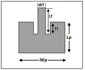
A linearly polarized single band antenna has been designed at 33.5 GHz frequency having the configuration as shown in Figure 2. The design uses the substrate of Fr-4(Lossy) material with dielectric constant 4.3 and thickness ‘h’. The physical parameters related to the design have been computed using the standard relations and optimization techniques [12-14] and are presented in Table 1. In order to ensure the proper impedance matching and simplified design, inset feed technique is used. The designed antenna has been modeled and simulated in CST Microwave studio.
Figure 2. Configuration of the 33.5 GHz antenna
Table 1. Optimised parameters of proposed antenna design
|
Parameter |
Value (mm) |
|
Patch Length (Lp) |
2.034 |
|
Patch Width (Wp) |
2.752 |
|
Length of Ground (Lg) |
4.30 |
|
Width of Ground (Wg) |
5.08 |
|
Substrate thickness (h) |
0.45 |
|
Length of Feedline (Lf) |
1.73 |
|
Width of Feedline (Wf) |
0.52 |
|
Inset depth (Fi) |
0.79 |
3.1 Simulation results
The characteristics of the designed RMSA such as return loss, VSWR, gain, directivity, bandwidth have been investigated by performing full wave simulations using CST Microwave Suite. The results have been plotted and discussed as following:
3.1.1 Return loss
The return loss characteristics of the designed MMW band RMSA has been extracted and plotted as shown in Figure 3. The plot shows that the antenna has the minimum reflection loss of -16.33 dB at the resonant frequency of 33.5 GHz which implies that there is very good impedance matching between the antenna and feed line. The bandwidth of the antenna has also been calculated using the same plot and its value is 0.76 GHz.
Figure 3. Simulated return loss of designed MMW band antenna
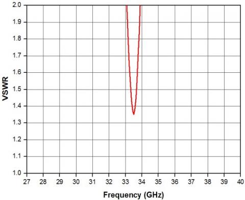
3.1.2 VSWR
The Voltage Standing Wave Ratio (VSWR) response of the designed antenna is shown in Figure 4. The plot shows that the antenna has the VSWR value of 1.36 at the resonant frequency 33.5 GHz. This is well below the standard value of 2.0 [15]. The low VSWR indicates that the reflections are very less.
Figure 4. Simulated VSWR of designed MMW antenna
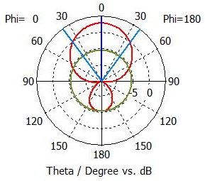
3.1.3 Radiation pattern
The radiation pattern of the designed antenna has been plotted as shown in Figure 5. From this plot it is clear that the antenna achieves a gain and directivity of 2.58 dB and 6.29 dBi, respectively.
Similar single patch RMSA antennas were designed at 1.8 GHz, 2.4 GHz and 5.5 GHz respectively and simulation studies of all these were conducted. The results of the simulation study regarding different parameters of these antennas are given in Table 2. For comparative study, the parameters obtained for RMSA antenna designed for 33.5 GHz frequency are also included in the table. From the table it is very clear that proposed RMSA antenna at 33.5 GHz MMW antenna has relatively very compact dimensions of 2.03 mm×2.75 mm which makes it possible to design large antenna arrays on a small footprint as compared to the antenna designed at 1.8 GHz, 2.4 GHz and 5.5 GHz frequencies. However, the antenna achieves the maximum gain of 2.58 dB and a bandwidth of 0.76 GHz only. Both these parameters can however be further improved using array configuration. This has been done as elaborated in following sub section.
Figure 5. Radiation pattern at 33.5 GHz
Table 2. Result summary of designed antennas at different frequency bands
|
Antenna |
1.8 GHz (L Band) |
2.4 GHz (S Band) |
5.5 GHz (C Band) |
33.5 GHz (Ka Band) |
|
Physical Parameters (mm) |
L=38.32 W= 51.37 Wf= 8.71 h=4.512 |
L=31.14 W=38.39 Wf=6.632 h=2.407 |
L=12.54 W=16.75 Wf=2.89 h=1.253 |
L= 2.034 W=2.752 Wf= 0.52 h= 0.45 |
|
Gain (dB) |
3.67 |
3.15 |
2.97 |
2.58 |
|
VSWR |
1.41 |
1.50 |
1.56 |
1.36 |
|
BW (MHz) |
70.6 |
73.5 |
155.5 |
760 |
|
Pmax (mW/m2) |
185.3 |
164.2 |
157.4 |
144.0 |
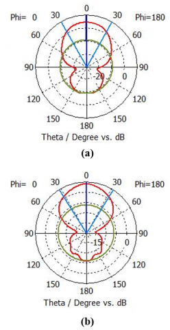
The gain of proposed single patch RMSA is 2.58 dB at 33.5 GHz and in order to enhance the overall gain, the design of the proposed antenna is extended to a center feed and end feed 1×3 antenna array configurations as shown in Figure 6(a, b). The antenna elements used in the array are identical and are designed according to the procedure given in section II. The inter element spacing is kept 4.98 mm which is greater than 0.5λ, to avoid the mutual coupling effect [16].
The simulated studies of the proposed antenna arrays were carried out and the results of the study regarding radiation pattern and VSWR are plotted as shown in Figure 7 and 8. The results are also summarized in Table 3 along with the designed single patch RMSA for comparison. It can be seen that a considerable enhancement in the gain, directivity, bandwidth, VSWR and radiated power is achieved using the arrays which is more remarkable in case of a center fed array as the power is symmetrically distributed to the adjacent antennas of the feeding element. Depending on the particular application requirements, the configuration can be further extended to 1×5, 1×7, 1 × 9 antenna arrays and so on.
Figure 6. Layout of (a) 1×3 center feed (b) 1×3 end feed antenna array
Figure 7. Radiation pattern of (a) 1×3 end feed (b) 1×3 center feed antenna array
Figure 8. VSWR of (a) 1×3 center feed (b) 1×3 center feed antenna array
Table 3. Result summary of designed antennas at 33.5 GHz
|
Parameter |
Configuration |
||
|
Single patch |
End Feed Array |
Center Feed Array |
|
|
Gain (dB) |
2.58 |
3.48 |
4.731 |
|
Directivity(dBi) |
6.29 |
6.87 |
7.960 |
|
VSWR |
1.36 |
1.26 |
1.04 |
|
BW (GHz) |
0.76 |
0.98 |
1.21 |
|
Pmax(mW/m2) |
144 |
186 |
237 |
The proposed MMW antenna has been fabricated using the photolithography process and the return loss results are measured using the VNA. The photo prototype of the fabricated antenna and its measured results are given in Figure 9 and 10, respectively. The slight deviation between the measured and simulated results could be attributed to the tolerances associated with the fabrication process as well as to measurement errors.
Figure 9. Fabricated antenna protype (a) Mask (b) antenna under test
Figure 10. Measured and simulation results of return loss
The equivalent circuit of the proposed RMSA antenna at 33.5 GHz is shown in Figure 11. This has been drawn using the Cavity model [17]. According to this model a microstrip antenna is represented by a parallel RLC resonant circuit, where Ra, La and Ca are the equivalent resistance, inductance and capacitance of the given antenna and ‘Xf’ is the inductive feed point reactance.
Figure 11. Equivalent circuit of designed antenna
The equivalent circuit parameters are obtained using the standard relations [18, 19] given below:
${{C}_{a}}=\frac{{{\varepsilon }_{e}}{{\varepsilon }_{0}}{{L}_{P}}{{W}_{P}}}{2h}\cdot \frac{1}{Co{{s}^{2}}(\beta )}$ where,$\beta =\frac{\pi zo}{{{L}_{P}}}$
$La=\frac{1}{2\pi {{f}_{r}}Ca}$ and $Ra=\frac{Q}{2\pi {{f}_{r}}Ca}$
where, Lp = Patch Length, Wp = Patch Width
zo = feed point location in z direction
Ɛe = Effective dielectric constant
Ɛo = Free Space Permittivity.
h = substrate thickness
fr= 33.5 GHz and Q = 44
The input impedance Zin(f) at feed point of the equivalent circuit can be written as [20]:
$Zin(f)=\frac{1}{\frac{1}{Ra}+\frac{1}{j\omega La}+j\omega Ca}+Xf$ (1)
Or, $Zin\text{ }(f)=({{R}_{p}}+j{{X}_{p}})+Xf$
In terms of magnitude above equation can also be written as:
$|{{Z}_{in}}(f)|=\frac{1}{\sqrt{{{\left( \frac{1}{Ra} \right)}^{2}}+{{\left( \frac{1}{\omega La}-\omega Ca \right)}^{2}}}}+\omega {{L}_{f}}$ (2)
The reflection coefficient of the equivalent circuit can be calculated as:
$\Gamma =\frac{{{Z}_{in}}-{{Z}_{o}}}{{{Z}_{in}}+{{Z}_{o}}}$ (3)
where, Zin = Input impedance
Z0=Characteristic Impedance
Using equation (3), Return loss (RL) of the circuit in dB is given by:
$RL=-20\log (\Gamma )$ (4)
Figure 12. Comparison of (a) input impedance (b) return loss of equivalent circuit and simulated antenna
The input impedance and the return loss results of the equivalent circuit are plotted using (3) and (4) and compared with that of the simulated antenna results as shown in Figure 12. It is observed that a good agreement is realized between the modeled equivalent circuit and the simulated antenna results.
A compact single band inset fed RMSA antenna has been proposed and investigated for MMW communication applications. The antenna has compact dimensions of 2.03 mm×2.75 mm and resonates at 33.5 GHz with a return loss of -16.33 dB and VSWR of 1.36. It also achieves a reasonable gain and bandwidth of 2.58 dB and 0.76 GHz respectively. To enhance the gain and other antenna parameters, a 1×3 center feed and end feed antenna arrays have been proposed, designed and investigated. The simulation investigations of the antenna arrays show reasonably good improvement in all the parameters viz. gain, directivity, bandwidth, VSWR and radiated power. The feasibility of the proposed antenna has been tested experimentally and also analysed using the equivalent circuit model. A good agreement has been realized between the results obtained using equivalent circuit model, experimental study and the simulation results.
In future, this work will be extended to design the multiband MMW antenna in order to support wide range of applications in next generation mobile networks.
[1] Wang, Y., Shi, Z. (2016). Millimeter-wave mobile communications. 5G Mobile Communications, 117-134. https://doi.org/10.1007/978-3-319-34208-5_5
[2] Rappaport, T.S., Murdock, J.N., Gutierrez, F. (2011). State of the art in 60-GHz integrated circuits and systems for wireless communications. Proceedings of the IEEE, 99(8): 1390-1436. https://doi.org/10.1109/jproc.2011.2143650
[3] Farooq, U., Rather, G.M. (2018). Millimeter wave (MMW) communications for fifth generation (5G) mobile networks. Progress in Advanced Computing and Intelligent Engineering, 714: 97-106. https://doi.org/10.1007/978-981-13-0224-4_9
[4] Yeo, K.S., Boon, C.C., Yi, X., Meng, F.Y. (2019). Millimeter-wave communication systems. CMOS Millimeter-Wave Integrated Circuits for Next Generation Wireless Communication Systems, pp. 3-37. https://doi.org/10.1142/9789811202612_0001
[5] Huang, K.C., Edwards, D.J. (2008). Millimetre Wave Antennas for Gigabit Wireless Communications. Wiley; 1.
[6] Singh, D., Gardner, P., Hall, P.S. (1997). Miniaturised microstrip antenna for MMIC applications. Electronics Letters, 33(22): 1830. https://doi.org/10.1049/el:19971240
[7] Du Preez, J., Sinha, S. (2016). Millimeter-wave antennas: Configurations and applications. Signals and Communication Technology. https://doi.org/10.1007/978-3-319-35068-4
[8] Pozar, D.M. (1992). Microstrip antennas. Proceedings of the IEEE, 80(1): 79-91. https://doi.org/10.1109/5.119568
[9] Zhang, Y.P., Liu, D.X. (2009). Antenna-on-chip and antenna-in-package solutions to highly integrated millimeter-wave devices for wireless communications. IEEE Transactions on Antennas and Propagation, 57(10): 2830-2841. https://doi.org/10.1109/tap.2009.2029295
[10] Haraz, O.M., Alshebeili, S.A., Sebak, A.R. (2015). Low-cost high gain printed log-periodic dipole array antenna with dielectric lenses for V-band applications. IET Microwaves, Antennas & Propagation, 9(6): 541-552. https://doi.org/10.1049/iet-map.2014.031
[11] https://www.3ds.com/products services/simulia/products/cst-studio-suite/, accessed on 11 May, 2019.
[12] Kumar, G.P.K. (2003). Broadband microstrip antennas. Artech House.
[13] Matin, M.A., Sayeed, A.I. (2010). A design rule for inset-fed rectangular microstrip patch antenna. WSEAS Transactions on Communications, 9(1): 63-72.
[14] Siakavara, K. (2011). Methods to design microstrip antennas for modern applications. Microstrip Antennas. https://doi.org/10.5772/14676
[15] Raju, G.S.N. (2006). Antennas and wave propagation. Pearson Education India.
[16] Craeye, C., González-Ovejero, D. (2011). A review on array mutual coupling analysis. Radio Science, 46(2). https://doi.org/10.1029/2010rs004518
[17] Garg, R., Bhartia, P., Bahl, I., Ittipiboon, A. (2001). Microstrip Antenna Design Handbook. Artech House Inc.
[18] Bahl, I.J., Bhartia, P. (1980). Design considerations in microstrip antenna fabrication. 10th European Microwave Conference. https://doi.org/10.1109/euma.1980.332817
[19] Shivnarayan, Vishvakarma, B.R. (2004). Analysis of slot loaded microstrip patch antenna. IEEE Antennas and Propagation Society Symposium. https://doi.org/10.1109/aps.2004.1331861
[20] Ansarizadeh, M., Ghorbani, A., Abd-Alhameed, R.A. (2008). An approach to equivalent circuit modeling of rectangular microstrip antennas. Progress in Electromagnetics Research B, 8: 77-86. https://doi.org/10.2528/pierb08050403