Benyettou Loutfi
© 2019 IIETA. This article is published by IIETA and is licensed under the CC BY 4.0 license (http://creativecommons.org/licenses/by/4.0/).
OPEN ACCESS
An open fault detection and analysis method for Multilevel Inverter based on Signal Processing is proposed in this paper. A reconfiguration method is also discussed. The output voltage is used as a diagnostic signal to detect the fault types and locations. In this paper, characteristics of open transistor faults in Multilevel Inverter (cascaded H-bridge seven-level) three-phase PWM-controlled shunt active power filter are determined. Phase currents cannot be trusted as fault indicator, like done in many research works in this field, since their waveforms change slightly in the presence of open transistor fault. The proposed method uses H bridges output voltages to determine the faulty phase, the faulty bridge and more precisely, the open fault transistor. The expected and simulation results are in good agreement with each other, which represents the proposed method can perform satisfactorily to detect the fault types and locations.
active power filter, multilevel inverter, PWM-controlled, open transistor fault, THD, mean values
Multilevel inverter offers interesting advantages such as possibility of operation in medium, high voltage and high power applications, providing a better voltage waveform with low total harmonic distortion for electric machines applications, output filter elimination, dv/dt transient reduction during commutation, low EMI emissions by overvoltages and power loss reduction [1]. Diode-clamped, cascaded-bridges and flying capacitors are the most used multilevel inverters in industry [2-3]. However, the number of switches needed in the topology increases with the number of levels and, although the switches may be highly reliable, a system's fault probability will become increased [4-5]). An unbalanced voltage is generated when a fault occurs which can produce permanent damage to the load or complete system failure [6-7].
Studies about fault detection in multilevel inverter and even fault-tolerant multilevel inverter have been focused on power systems' fault analysis [8-10] as first step to conceive different techniques for obtaining a three-phase balanced output voltage [4-5, 11-12]. Xiao Min analyzed a flying capacitor-based four-level inverter using the material redundancy technique (using extra components) [13]. A cascaded H-bridge multilevel inverter with an additional leg and redundancy technique regarding change of pulse width modulation (PWM) when a fault occurs has also been described [7]. Others [4-6] have shown tolerant control for an asymmetric cascade multilevel inverter using material redundancy. Other works have analyzed a three-level diode clamped multilevel inverter and also used extra components to tolerate faults [14]. Some of these studies used protection functions [15], e.g. passive protection could become activated according to fault time duration [16]. Several papers [17-18] have presented a cascade multilevel inverter and fault-tolerant technique used to change PWM modulation in semiconductor power devices. Others works [19] have dealt with a fault-tolerant system for electrical machines, such as induction motor [20], besides focusing on Aerospatiale applications and electric vehicle applications [21]. Others considered the most common faults in static converters (short and open circuit transistors) [22]. In the same direction, D. Kastha and B. K. Bose considered various fault modes of a two level voltage source PWM inverter system for induction motor drive [23]. They have studied rectifier diode short circuit, inverter transistor base driver open and inverter transistor short-circuit conditions. However, they do not propose to reconFigure the inverter topology.
De Araujo Ribeiro R. L. et al. investigated fault detection of open-switch damage in two level voltage source PWM motor drive systems [24]. They mainly focused on detection and identification of the power switch in which the fault has occurred. In another paper, they investigated the utilization of a two-leg based topology when one of the inverter legs is lost. Then the machine operates with only two stator windings [25]. They proposed to modify PWM control to allow continuous free operation of the drive. E. R. C. Da Silva et al. have studied fault tolerant active power filter system [26]. They proposed to reconFigure power converter and PWM control and examined a fault identification algorithm. T. Benslimane used active filter output currents mean values polarities to detect and localize open switch faults in shunt active three-phase filter based on two level voltage source inverter controlled by current Hysteresis controllers [27]. Surin Khomfoi used artificial neural networks for the diagnostic of open loop PWM controlled cascaded h-bridge multilevel inverter drives. He used inverter output voltages FFT analysis to extract principle component as fault indicators for simultaneous transistor and diode open switch fault [28]. Karimi S. and Pourea P. et al. put into practice an FPGA (Field Programmable Gate Array)-based online fault tolerant control technique of parallel active power filter based on two level three-phase voltage source inverter with redundant leg [29-30].
Most of mentioned works about multilevel inverter faults detection are related to electrical machine drives applications. The few of them, which are related to static applications such as active power filters, considered only two-level voltage source inverter.
This present paper deals with open transistor faults characterization in cascaded H-bridge Seven-level three-phase PWM controlled shunt active power filter. Phase currents can’t be trusted as fault indicator since their waveforms are slightly changed in the presence of open transistor fault. The proposed method uses H-bridges output voltages to determine the faulty phase, the faulty bridge and more precisely, the open faulty transistor. After a brief description of H-bridge seven-level inverter used as active power filter system in section 2, harmonic currents identification method is presented in section 3 followed by introducing the PWM control technique of seven-level inverter in section 4. Open transistor faults characterization of seven-level inverter is discussed in section 5 based on simulation results and their analysis.
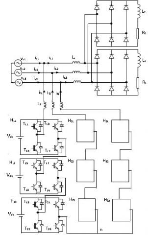
Figure 1 presents the cascaded H-bridge seven -level three-phase shunt active power filter connected to balanced power grid (vsi for i={1, 2, 3}) powering a three phase diode rectifier feeding a variable values series (R, L) load. The active filter is composed, in each phase, of three voltage source H-bridge inverters (Hij, i=1,2,3, j=1,2) with 4 bidirectional electronic switches (transistor + diode) for each one. The filter is connected to the power grid through inductive filter Lf for each phase.
Figure 1. Cascaded H-bridge seven-level three-phase shunt active power filter topology
The output currents of the shunt active filter are controlled to provide the identified reactive and harmonic currents generated by the non-linear load.
Several faulty cases can occur: power transistor or power transistor driver can be faulty. In each case, it results in the following models:
- A transistor is closed instead of being normally open. It results in a short-circuit of the DC voltage source. To isolate the faulty switch as fast as possible, one can use fuses.
- A transistor is open instead of being normally closed. The filter may continue injecting currents to the power supply. These currents don't cause any prompt risk because they are at the same range level as the case of no-fault condition. However, the filter, in this case, may pollute more the power supply instead of elimination of harmonic currents of non-linear load. This case is considered in this paper.
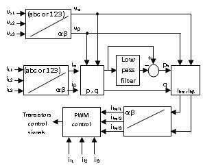
Figure 2 presents a block diagram of the proposed control system. The major advantage of this control principle is its simplicity and easiness to be implemented. The task of this control is to determine the current harmonic references to be generated by the active filter.
Figure 2. Block diagram of the harmonic currents identification
They are defined using classical active and reactive power method proposed by Akagi [31].
By supposing that the main power supply voltages are sinusoidal, current harmonic references will be calculated like indicated in [32].
($α, β$) voltage components at coupling point of active filter ($vα, vβ$) and currents ($iα, iβ$) are defined by the classical Concordia transformation:
$\begin{matrix} \left[ \begin{matrix} x\alpha \\ {} \\ x\beta \\\end{matrix} \right] & \text{=}\begin{matrix} {}^{2}/{}_{3} & {} & \left[ \begin{matrix} 1 & {} & -1/2 & {} & -1/2 \\ {} & {} & {} & {} & {} \\ 0 & {} & -\sqrt{3}/2 & {} & \sqrt{3}/2 \\\end{matrix} \right] & \begin{matrix} {} & \left[ \begin{matrix} x1 \\ {} \\ x2 \\ {} \\ x3 \\\end{matrix} \right] \\\end{matrix} \\\end{matrix} & {} & {} & {} \\\end{matrix}$ (1)
where x={v, vs, i, iL}
The instantaneous real and imaginary powers, noted by p and q, are calculated by:
$\begin{matrix} \left[ \begin{matrix} p \\ {} \\ q \\\end{matrix} \right] & \text{=}\begin{matrix} {} & {} & \left[ \begin{matrix} v\alpha & {} & {} & {} & v\beta \\ {} & {} & {} & {} & {} \\ -v\beta & {} & {} & {} & v\alpha \\\end{matrix} \right] & \begin{matrix} {} & \left[ \begin{matrix} i\alpha \\ {} \\ i\beta \\\end{matrix} \right] \\\end{matrix} \\\end{matrix} & {} & {} & {} \\\end{matrix}$ (2)
These powers are then filtered by high-pass filters, which gives ph and qh and the harmonic components of the currents will be:
$\left[ \begin{matrix} {{i}_{h1}} \\ {{i}_{h2}} \\ {{i}_{h3}} \\\end{matrix} \right]\text{=}\left[ \begin{matrix} {{i}_{fref1}} \\ {{i}_{fref2}} \\ {{i}_{fref3}} \\\end{matrix} \right]\text{=}\frac{1}{v_{\alpha }^{2}+v_{\beta }^{2}}\left[ \begin{matrix} 1 & {} & 0 \\ -1/2 & {} & -\sqrt{3}/2 \\ -1/2 & {} & \sqrt{3}/2 \\\end{matrix} \right]\left[ \begin{matrix} {{v}_{a}} & {{v}_{\beta }} \\ -{{v}_{\beta }} & {{v}_{a}} \\\end{matrix} \right]\left[ \begin{align} & {{p}_{h}} \\ & {{q}_{h}} \\\end{align} \right]$ (3)
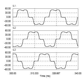
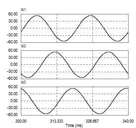
Non linear load (diode rectifier) produces non linear currents which contain harmonics currents (Figure 3.1.a, Figure 3.1.b and Figure 4.1). Compensating the harmonic currents is guaranteed by controlling the seven-level voltage source inverter to generate phase currents similar to harmonic currents of non linear load leading to get approximately sinusoidal electric grid phase currents (Figure. 3.1.c).
Cascaded H-bridge seven-level three-phase shunt active power filter is controlled by horizontally shifted carriers PWM control technique. The difference between active filter current and identified harmonic currant is introduced to the PI regulator. This latter outputs reference signal that is compared to 6 carriers shifted by 60° one to another to generate transistors control signals (Figure 3.2.d).
(a) Non-linear load phase currents
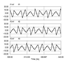
(b) Active filter phase currents and their references
(c) Power grid phase currents
Figure 3.1 Simulation results of H-bridge seven-level three-phase shunt active power filter in normal operating condition (results1)
d. Reference signals and carriers of PWM control technique
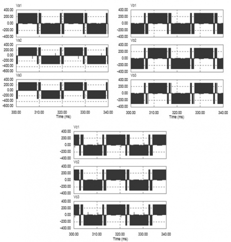
e. Bridges output voltages
Figure 3.2 Simulation results of H-bridge seven-level three-phase shunt active power filter in normal operating condition (results2)
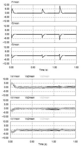
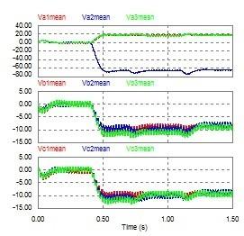
f. Phase currents and bridges output voltages mean values
Figure 3.3 Simulation results of H-bridge seven-level three-phase shunt active power filter in normal operating condition (results 3)
Figure 4.1 Active filter phase currents and their references in T11 open fault condition at t=0.4 s
This section presents analysis of simulation results obtained with PSIM simulator for PWM controlled cascaded H-bridge seven-level three-phase shunt active power filter with normal and faulty open transistors condition. Simulation parameters are:
- Main source grid: $220V, 50 Hz$;
- Non-linear load:
$R1=10 Ohm for t ϵ [0,0.7sec], R1=5 Ohm for t ϵ [0.7,1.5sec], L1=0.005 H, R2=1000 Ohm for t ϵ [0,1.1sec], R2=5 Ohm for t ϵ [1.1, 1.5sec], L2=0.01 H, Ls=0.0015 H$;
- Active filter: $Vdc=300 V, Lf=0.004 H, fp=5000 Hz (PWM carriers frequency), Proportional-integral (PI) regulators: Gain Kp=0.5, time constant Ti=0.001$.
These parameters are chosen to reduce THD of main source currents below 5%. It is noticed that filter output currents are superimposed to their harmonic identified reference currents and that grid source currents are almost sinusoidal (Figure 3.1.b, Figure 3.1.c). It is also remarked that PI output signals (reference signals of PWM control technique: Vref1, Vref2, Vref3) are symmetric (Figure 3.2.d) which produce symmetric output voltages (Va1, Va2, Va3, Vb1, Vb2, Vb3, Vc1, Vc2, Vc3) (Figure 3.2.e) with small mean values Va1mean, Va2mean, Va3mean, Vb1mean, Vb2mean, Vb3mean, Vc1mean, Vc2mean, Vc3mean (Figure 3.3.f).
Faulty phase, faulty bridge and more precisely, open faulty transistor detection is based on the calculation of zero harmonic component (mean value, dc offset) included in H bridges output voltages. This is done by using a second-order low-pass filter with cut-off frequency of 5 Hz and damping ratio of 0.7.
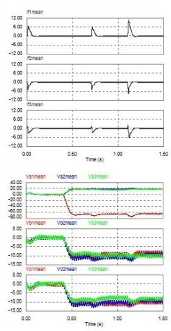
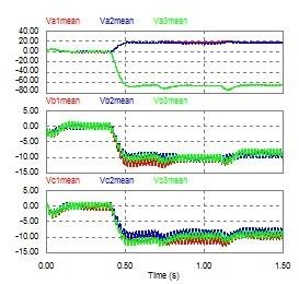
When a transistor is in open fault condition, the PI regulators will output a PWM reference signal in a way to compensate the error due to that faulty transistor. In this case, PWM reference signals will be asymmetric making H bridges output voltages asymmetric too with significant mean values specific to each faulty transistor (Figure 4.2, Figure 4.3, Figure 5, Figure 6, Figure 7 and Figure 8). It is remarked that active filter phase currents are slightly disturbed by the transistor fault keeping small mean values for different non-linear loads (Figure 3.3. f, Figure 4.3). In fact, normal operating bridges in each phase compensate the faulty one especially for low rate currents.
Figure 4.2 Reference signals of PWM control technique and bridges output voltages in T11 open fault condition at t=0.4 s
A change in H bridges output voltages waveforms is defined as the instant at which a sudden increase or decrease is observed in the DC offset component of these voltages. A change is considered to have occurred in the H bridges output voltages mean values when they exceeds or falls below a given band (Figure 4.2, Figure 4.3, Figure 5, Figure 6, Figure 7 and Figure 8).
Phase 1 is linked to bridges H11, H12 and H13. If the open circuit faulty transistor is in phase 1, one of these bridges output voltages will have the maximum mean value ($Va1mean=±62 V, Va2mean=±62 V, Va3mean=±62 V$). If the faulty transistor is in bridge $H11 (T11, T12, T13, T14)$, this latter’s output voltage will have the maximum mean value ($Va1mean=±60 V$) (Figure 4.3.c, Figure 5, Figure 6). If the faulty transistor is in bridge $H12 (T15, T16, T17, T18)$, this latter’s output voltage will have the maximum mean value ($Va2mean=±62 V$) (Figure 7). If the faulty transistor is in bridge H13, this latter’s output voltage will have the maximum mean value ($Va3mean=±62 V$) (Figure 8). If one of the transistors T11 and T12 in bridge H11 is the faulty one, this bridge’s output voltage will have the maximum mean value with negative polarity ($Va1mean=-62 V$). If one of the transistors T13 and T14in bridge H11 is the faulty one, this bridge’s output voltage will have the maximum mean value with positive polarity ($Va1mean=+62 V$).
Figure 4.3 Phase currents and bridges output voltages mean values in T11 open fault condition at t=0.4s
The first phase three bridges open transistor faults characteristics are classified in Table 1. This table could be implemented practically using simple comparators with predefined threshold of H Bridges output voltages mean values.
Figure 5. Simulation results of H-bridge seven-level three-phase shunt active power filter in T13 open fault condition at t=0.4s
Figure 6. Simulation results of H-bridge seven-level three-phase shunt active power filter in T14 open fault condition at t=0.4s
Figure 7. Simulation results of H-bridge seven-level three-phase shunt active power filter in T15 open fault condition at t=0.4s
Figure 8. Simulation results of H-bridge seven-level three-phase shunt active power filter in T19 open fault condition at t=0.4 s
Table 1. H Bridges output voltages mean values corresponding to faulty open circuit transistors of phase 1
|
Open fault transistor |
Faulty bridge |
H Bridges output voltages mean values |
||||||||
|
Va1mean (V) |
Va2mean (V) |
Va3mean (V) |
Vb1mean (V) |
Vb2mean (V) |
Vb3mean (V) |
Vc1mean (V) |
Vc2mean (V) |
Vc3mean (V) |
||
|
T11 or T12 |
H11 |
-62 |
+19 |
+19 |
-10 |
-10 |
-9 |
-10 |
-10 |
-9 |
|
T13 or T14 |
H11 |
+62 |
-19 |
-19 |
+10 |
+10 |
+9 |
+10 |
+10 |
+9 |
|
T15 or T16 |
H12 |
+19 |
-62 |
+19 |
-10 |
-10 |
-9 |
-10 |
-10 |
-9 |
|
T19 or T20 |
H13 |
+19 |
+19 |
-62 |
-10 |
-10 |
-9 |
-10 |
-9 |
-10 |
In this paper a simple, reliable and efficient open transistor faults characterization technique in shunt active three-phase filter based on H-bridge seven-level three-phase PWM-controlled shunt active power filter is presented. H bridges output voltages mean values are used to characterize different open transistor faults and permit the determination of faulty phase, faulty bridge and more precisely the faulty transistor.
Simulation results demonstrate that when optimizing active filter parameters, the zero harmonic component strategy can be used with robustness to detect and localize the open faulty switch in active filter inverter.
Abbreviations and symbols are listed below:
PWM: Pulse Width Modulation
FFT: Fast Fourier Transform
DC: Direct current
PI: Proportional-Integral
PSIM: Power Simulation (Software)
THD: Total Harmonic Distortion
Kp: Gain of proportional-Integral regulator
Ti: Time constant of proportional-Integral regulator
[1] Cortés C, Deprez W, Driesen J, Pérez J. (2008). Determinación de pérdidas eléctricas en motores de inducción modelados electromagnéticamente con el método de los elementos finitos. Ingeniería e Investigación, Universidad Nacional de Colombia, Bogotá, Colombia 28(3): 64-74.
[2] Bin W. (2006). High Power Converters and AC Drives. Wiley Inter-Science, Toronto Canada, 80-87. https://doi.org/10.1002/0471773719
[3] Jae-Chu L, Tae-Jin K, Dae-Wook K, Dong-Seok H. (2006). A Control Method for Improvement of Reliability in Fault Tolerant NPC Inverter System. Power Electronics Specialists Conference, PESC'06, Jeju, Korea, 1304-1308. https://doi.org/10.1109/PESC.2006.1711954
[4] Mingyao M, Lei H, Alian C. (2007). Reconfiguration of carrier-based modulation strategy for fault tolerant multilevel inverters. IEEE Transactions on Power Electronics 22(5): 2050-2060. https://doi.org/10.1109/TPEL.2007.904249
[5] Ma MY, Hu L, Chen AL, He XN. (2007). Reconfiguration of carrier-based modulation strategy for fault tolerant multilevel inverters. 31th Annual Conference of IEEE Industrial Electronics Conference, pp. 1048-1053. https://doi.org/10.1109/TPEL.2007.904249
[6] Barriuso P, Dixon J, Flores P, Morán L. (2009). Fault tolerant reconfiguration system for asymmetric multilevel converters using bi -directional power switches. IEEE Industrial Electronics Society 56(4): 1300-1306. https://doi.org/10.1109/TIE.2008.2005680
[7] Francois B, Hautier J. (2002). Design of a fault tolerant control system for a NPC multilevel inverter. 28th Annual Conference of IEEE Industrial Electronics Conference (IECON). Sevilla, Spain, pp. 1075-1080. https://doi.org/10.1109/ISIE.2002.1025937
[8] Aguayo J, Claudio A, Vela L, Gentile S. (2004). A survey of fault diagnosis methods for induction motors drives under inverter fault conditions. International Conference of Electrical and Electronics Engineering, (ICEEE). Acapulco Guerrero, México, pp. 367-372. https://doi.org/10.1109/ICEEE.2004.1433910
[9] Hernández LP, Flórez JM, Cebayos JB. (2009). A linear approach to determining an SVM-based fault locator's optimal parameters. Ingeniería e Investigación, Universidad Nacional de Colombia, Bogotá, Colombia 29(1): 76-8.
[10] Quiroga J. (2009). Detección de cortocircuito en el devanado de un motor sincrónico de imanes permanentes usando corriente de secuencia negativa en dominio tiempo. Ingeniería e Investigación. Universidad Nacional de Colombia, Bogotá, Colombia 29(2): 48-52. http://www.scielo.org.co/pdf/iei/v29n2/v29n2a07.pdf
[11] Li SM, Xu LY. (2006). Strategies of fault tolerant operation for three-level PWM inverters. IEEE Trans. Power Electronics 21(4): 933-940. https://doi.org/10.1109/TPEL.2006.876867
[12] Wei SM, Wu B, Rizzo S, Zargari NR. (2004). Comparison of control schemes for multilevel inverter with faulty cells. 30th Annual Conference of IEEE Industrial Electronics Conference, IECON. Busan, Korea, pp. 1817-1822. https://doi.org/10.1109/IECON.2004.1431859
[13] Kou XM, Corzine K, Familian Y. (2003).A unique fault-tolerant design for flying capacitor multilevel inverter. IEEE Trans. Power Electronics 19(4): 979-984. https://doi.org/10.1109/IEMDC.2003.1211314
[14] Gun-Tae P, Tae-Jin K, Dae-Wook K, Dong-Seok H. (2004). Control method of npc inverter for continuous operation under one phase fault condition. Power Electronics Specialists Conference, PESC'04, Aachen, Germany, pp. 2188-2193. https://doi.org/10.1109/IAS.2004.1348780
[15] Fuchs F. (2003). Some Diagnosis methods for voltage source inverters in variable speed drives with induction machines a survey. 29th Annual Conference of IEEE Industrial Electronics Conference (IECON), pp. 1378-1385. https://doi.org/10.1109/IECON.2003.1280259
[16] Sun Z, Wang J, Howe D, Jewell G. (2009). Analytical prediction of short-circuit current in fault-tolerant permanent magnet machines. IEEE Transactions on Industrial Electronics 55(12): 4210-4217. https://doi.org/10.1109/TIE.2008.2005019
[17] Wei SM, Wu B, Fahai L, Sun XD. (2003). Control method for cascaded H-bridge multilevel inverter with faulty power cells. Applied Power Electronics Conference and Exposition 9(1): 261-267. https://doi.org/10.1109/APEC.2003.1179224
[18] Khomfoi S, Tolbert L. (2006). A reconfiguration technique for multilevel inverters incorporating diagnostic system based on neural network. Computers in Power Electronics, 317-323. https://doi.org/10.1109/COMPEL.2006.305633
[19] Lillo LD, Empringham L, Wheeler P, Khwan-On S. (2010). Multiphase power converter drive for fault-tolerant machine development in aerospace application. IEEE Transactions on Industrial Electronics 57(2): 575-583. https://doi.org/10.1109/TIE.2009.2036026
[20] Thybo C. (2001). Fault-tolerant control of induction motor drive applications. Proceedings of the American Control Conference 25(4): 2621-2622. https://doi.org/10.1109/ACC.2001.946266
[21] Xiong Y, Cheng X, Shen Z, Chunting M, Hongjie M, Garg V. (2008). Prognostic and warning system for power-electronic modules in electric, hybrid electric, and fuel-cell vehicles. IEEE Transactions on Industrial Electronics 55(6): 2268-2276. https://doi.org/10.1109/TIE.2008.918399
[22] Lu B, Sharma S. (2009). A literature review of IGBT fault diagnostic and protection methods for power inverters. IEEE Transactions on Industrial Electronics 45(5): 1770-1777. https://doi.org/10.1109/TIA.2009.2027535
[23] Kastha D, Bose B. (1994). Investigation of fault modes of voltage-fed inverter system for induction motor drive. IEEE Transactions on Industry Applications 30(4): 1028-1038. https://doi.org/10.1109/28.297920
[24] Ribeiro RDA, Jacobina C, Silva ED, Lima A. (2003). Fault detection of open-switch damage in voltage-fed PWM motor drive systems. IEEE Transactions on Power Electronics 18(2): 587-593. https://doi.org/10.1109/TPEL.2003.809351
[25] Beltrao de Rossiter Correa M, Brandao Jacobina C, Cabral da Silva E, Nogueira Lima A. (2001). An induction motor drive system with improved fault tolerance. IEEE Transactions on Industry Applications 37(3): 873-879. https://doi.org/10.1109/28.924770
[26] Jacobina C, Correa M, Pinheiro R, Lima A, Silva ED. (2001). Improved fault tolerance of active power filter system. IEEE 32nd Annual Power Electronics Specialists Conference PESC, pp. 17-21. https://doi.org/10.1109/PESC.2001.954353
[27] Benyettou L, Benslimane T. (2017). Analysis of transistor open fault diagnosis for shunt active power filters. Indonesian Journal of Electrical Engineering and Computer Science 5(3): 521-529. https://doi.org/10.11591/ijeecs.v5.i3.pp521-529
[28] Khomfoi S. (2007). Fault diagnostic system for cascaded h-bridge multilevel inverter drives based on artificial intelligent approaches incorporating a reconfiguration technique. Doctorate thesis, University of Tennessee, USA.
[29] Pourea P, Weberb P, Theilliol D, Saadate S. (2009). Fault tolerant control of a three-phase three-wire shunt active filter system based on reliability analysis. Electric Power Systems Research 79: 325-334. https://doi.org/10.1016/j.epsr.2008.07.003
[30] Karimi S. (2009). Continuité de service des convertisseurs triphasés de puissance et prototypage, application au filtre actif parallèle, Doctorate thesis, Henri Poincaré University, Nancy-I, France. https://hal.univ-lorraine.fr/tel-01748540/document
[31] Akagi H, Kanazawa Y, Nabae A. (1983). Generalized theory of the instantaneous reactive power filter. Proceedings of International Power Electronics Conference, pp. 1375-1386.
[32] Benyettou L, Benslimane T, Abdelkhalek O. (2017). Comparative study of different methods of active power compensation. Modelling, Measurement and Control A 90(4): 310-327.