Adriana Greco | Adriana R. Farina | Claudia Masselli*
OPEN ACCESS
Magnetic refrigeration is a promising and ecologic technology, alternative to the conventional vapor-compression refrigeration by the employment of solid-state materials as refrigerants instead of the fluid-state ones, own of vapour compression refrigeration. This emerging technology bases its operation on the MagnetoCaloric Effect (MCE), which is a physical phenomenon, related to solid-state materials with magnetic properties. For materials displaying simple magnetic ordering (i.e. paramagnetic to ferromagnetic phase transformations) a rapid increase in magnetic field causes a temperature rise in the material; likewise, a rapid reduction in the field causes cooling. This variation in temperature is called adiabatic temperature change.
In 1982 the Active Magnetic Regenerative refrigeration cycle, well known as AMR cycle was introduced. The innovative idea considers a magnetic Brayton cycle but the main innovation consists of introducing the AMR regenerator concept, i.e. the employment of the magnetic material itself both as refrigerant and as regenerator. A secondary fluid is used to transfer heat from the cold to the hot end of the regenerator. Substantially every section of the regenerator experiments its own AMR cycle, according to the proper working temperature. Through an AMR one can appreciate a larger temperature span among the ends of the regenerator.
magnetocaloric cooling, materials, magnetocaloric effect, curie temperature, thermodynamic cycles, active caloric regenerator
Nowadays, the refrigeration is responsible of more than 20% of the overall energy consumption all over the world and most modern refrigeration units are based on Vapor Compression Plants (VCP). The traditional refrigerant fluids employing VCP, i.e. CFCs and HCFCs, have been banned by the Protocol [1], because of their contribution to the disruption of the stratospheric ozone layer (Ozone-Depleting Potential substances ODPs). Over time it has been following periodical meetings among the Parties to the Montreal Protocol. Since 2000 the usage of HCFCs in new refrigerating systems was forbidden, letting HFCs the only fluorinated refrigerants allowed because of their zero ODP characteristic. Since 2009, each meeting related to Montreal protocol, initially dedicated to the phase-out of the substances depleting the stratospheric ozone layer, namely CFCs and HCFCs, had been leading to conflicting exchanges on high Global Warming Potential HFCs which replace CFCs and HCFCs most of the time. Year after year, human activities have been increasing the concentration of greenhouse gases in the atmosphere, thus resulting in a substantial warming of both earth surface and atmosphere. The impact of greenhouse gases on global warming is quantified by their GWP (Global Warming Potential). Thus, over the year measures to reduces global warming have been taken, beginning with the Protocol [2] and consequently with the EU regulations applying the prescriptions derived from it, like EU regulation 517/2014 [3] on fluorinated greenhouse gases.
The above-described general frameworks led scientific community to studying and applying [4, 5] resolutions with environmentally friendly gases, with small GWP and zero ODP: one of the most focused classes of new generation refrigerants is hydrofluoroolefins (HFO) [6, 7], descending of olefins rather than alkanes (paraffins) and they are known as unsaturated HFCs, with environmentally friendly behavior, quite low costs. Despite all these advances, it is essential to underline that a vapor compression plant produces both a direct and an indirect contribution to global warming. The former depends on the GWP of refrigerant fluids and on the fraction of refrigerant charge which is either directly released in the atmosphere during operation and maintenance or is not recovered when the system is scrapped. The indirect contribution is related to energy-consumption of the plant. In fact, a vapor compression refrigerator requires electrical energy produced by a power plant that typically burns a fossil fuel, thus releasing CO2 into the atmosphere. The amount of CO2 emitted is a strong function of the COP of the vapor compression plant.
For all these reason, in the last decades the interest of scientific community has oriented itself in studying and developing new refrigeration technologies of low impact in our ecosystem: a class of them is composed by solid-state cooling [8-10], which are gaining more and more attention, due to their potential in being performing and ecological methodologies. Recent discoveries of giant caloric effects [11-13] in some ferric materials have opened the door to the use of solid-state materials as an alternative to gases for conventional and cryogenic refrigeration.
Currently magnetocaloric refrigeration (MR) is among the most promising, eco-friendly, emerging solid-state techniques [14], whose main innovation consists in employing solid materials with magnetic properties as refrigerants, able to increase or decrease their temperature when interacting with a magnetic field. Instead of the fluid refrigerants, proper of vapour compression, a magnetocaloric refrigerant is a solid and therefore it has essentially zero vapour pressure, which means no direct ODP and zero GWP.
Specifically, magnetic refrigeration is related to magnetocaloric effect (MCE) [15], a physical phenomenon observed in some material with magnetic properties and it consists in an increment of temperature in the MCE material because of material's magnetization under adiabatic conditions. A regenerative Brayton based thermodynamical cycle, called Active Magnetic Regenerative refrigerant (AMR) cycle, is the one where magnetic refrigeration founds its operations. Therefore, Active Magnetic Regenerator is the core of a magnetic refrigerator system. It is a special kind of thermal regenerator made of material with magnetic properties, which works both as a refrigerant and as a heat regenerating medium. The performance of an AMR system strongly depends on the magnetocaloric effect of the magnetic material used to build the regenerator, on the geometry of the regenerator and on the operating conditions of the system. The cooling efficiency in magnetic refrigerators can reach 60% of the theoretical limit, as compared to the 40% achieved by the best vapor compression plant.
This paper aims to illustrate the peculiarities of this technology from the point of view of the physical phenomenon and the thermodynamic cycles.
Magnetocaloric effect is a physical phenomenon, related to solid-state materials with magnetic properties. MCE consists in a coupling between the entropy of the Magnetocaloric Material (MM) and the variation of an external magnetic field applied to the material, which causes magnetic ordering in the MM structure. If the magnetization is done isothermally, it will decrease the magnetic entropy of the material, by the isothermal entropy change ΔSM and, therefore, a change in the total entropy of the magnetic material is registered.
On the other side, if the magnetization occurs in an adiabatic process, without any interaction with the external environment, the total entropy of MM remains constant and the consequent decreasing in magnetic entropy is countered by an increase in the lattice and electron entropy contributions. This causes a heating of the material and a temperature increase given by the adiabatic temperature change (ΔTad). In Figure 1 the quantities ΔSM and ΔTad during an adiabatic magnetization of a ferromagnetic material are clearly visible.
Dually, under adiabatic demagnetization the magnetic entropy increases, causing a reduction in lattice vibrations and therefore a temperature decrease. At its Curie temperature, where is located its own magnetic phase transition, a MM shows the peak of MCE, in terms of ΔTad and ΔSM. This occurs because the two opposite forces (the ordering force due to exchange interaction of the magnetic moments, and the disordering force of the lattice thermal vibrations) are approximately balanced near the Curie point TC.
Hence, the isothermal application of a magnetic field produces a much greater increase in the magnetization (i.e., an increase of the magnetic order and, consequently, a decrease in magnetic entropy, ΔSM) near the Curie point, rather than far away from Tc. The effect of magnetic field above and below Tc is significantly reduced because only the paramagnetic response of the magnetic lattice can be achieved for T≫Tc, and for T≪Tc the spontaneous magnetization is already close to saturation and cannot be increased much more. Similarly, the adiabatic application of a magnetic field leads to an increase in the magnetic material temperature, ΔTad, which is also sharply peaked near the Tc.
Figure 1. Magnetocaloric effect detected as ΔSM and ΔTad in a ferromagnetic material where it is magnetized by magnetic field going from H0 to H1
The two possible magnetic phase changes that one can observe at the Curie point are First Order Magnetic Transition (FOMT) and Second Order Magnetic Transition (SOMT). At the Curie point a magnetic transition has FOMT characteristics when the material exhibits a discontinuity in the first derivative of the Gibbs free energy (G.f.e.), magnetization function, whereas has a SOMT behavior when the gap is detected in the second derivative of G.f.e., magnetic susceptibility, while its first derivative is a continuous function. Most of the magnetic materials order with a SOMT from a paramagnet to a ferromagnet, ferrimagnet or antiferromagnet.
Considering an internally reversible process, the MCE for SOMT materials can be evaluated as:
$\left(\Delta S_{M}\right)_{T}=\mu_{0} \int_{H_{i}}^{H_{f}}\left(\frac{\partial M}{\partial T}\right)_{H} d H$ (1)
$\left(\Delta T_{a d}\right)_{s}=-\mu_{0} \int_{H_{i}}^{H_{f}} \frac{T}{C_{H}}\left(\frac{\partial M}{\partial T}\right)_{H} d H$ (2)
For that reason, in a SOMT material, while $\left|(d M / d T)_{H}\right|$ exhibits its maximum value, one can register the peak of MCE, located at the Curie temperature or near absolute zero, respectively if the material is a ferromagnetic or paramagnetic. Instead in a FOMT material, the phase transition should ideally take place at constant temperature for an infinite value of $\left|(d M / d T)_{H}\right|$ resulting a giant magnetocaloric effect. The FOMT materials exhibit both an instantaneous orientation of magnetic dipoles and a latent heat correlated with the transition. Moreover, in some FOMT materials it is possible observing a coupled magnetic and crystallographic phase transition. Thus, in this case, applying a magnetic field to these FOMT materials, can produce both the magnetic state transition from a paramagnet or an antiferromagnet to a ferromagnet, simultaneously with a structural variation or a significant phase volume discontinuity but without showing a clear crystallographic alteration. Since that partial first derivatives of G.f.e. regarding T or H present a discontinuity at the first order phase transition, the bulk magnetization varies by ΔM and CH ideally has an infinite value at the Curie temperature. Therefore, the isothermal magnetic entropy change (ΔSM) in a FOMT material can be estimated by Eq. (3) coming from the Clasius-Clapeyron equation:
$\left(\Delta S_{M}\right)_{T}=\left(\frac{d H}{d T_{c}}\right)_{e q}(\Delta M)_{T}$ (3)
where the derivative is kept at equilibrium.
The discovery of giant magnetocaloric effect in Gd5(Si4-xGex), reported by Pecharsky and Gschneidner [11], stimulated a considerable growth of research to both find new materials where the effect is just as potent and to understand the role of magneto-structural transitions play in its enhancement. Giant MCE in FOMT materials, already observed, comes out since it is the result of two phenomena: the conventional magnetic entropy-driven process (magnetic entropy variation $\Delta S_{M}$) and the difference in the entropies of the two crystallographic alterations (structural entropy variation $\Delta S_{S T}$). The second term considers the greater contribution due to entropy variation in FOMT with respect to SOMT materials:
$(\Delta S)_{T}=\left(\Delta S_{M}\right)_{T}+\left(\Delta S_{S T}\right)_{T}$ (4)
Assuming $T / C_{H}$ constant, in a FOMT material $\Delta T_{a d}$ could be estimated as:
$\left(\Delta T_{a d}\right)_{s}=-\mu_{0}\left(\frac{T}{C_{H}}\right)\left(\frac{d H}{d T_{c}}\right)(\Delta M)_{T}$ (5)
The peak of adiabatic temperature variation is greater in most of the FOMT than SOMT materials.
There are fundamental differences in the behavior of FOMT and
SOMT materials:
in a first order transition the MCE is concentrated in a narrow temperature range, whereas in a second order the transition spread over a broad temperature range.
In a SOMT materials the adiabatic temperature variation is nearly immediate whereas it doesn't happen in FOMT materials because of the consequent alteration in their crystallographic structure, which produces a displacement of the atoms, needing thus of an amount of time required many orders of magnitude larger. The non-instantaneous response to the magnetic field of FOMT material, could become a significant problem since the operation frequencies usually adopted by magnetic refrigerators are in [0.5÷10] Hz range, where the delay in materials' answer could assume significant values.
A substantial hysteresis has generally been detected [16, 17] in FOMT materials, whereas it is very low in SOMTs. The consequences of hysteresis when analyzing the MCE are: i) history dependence: parameters such as magnetization and heat capacity now become non-single valued functions of temperature and field; ii) energy dissipation: heat is dissipated during the magnetization process, and the dissipation adds heat to the system.
The large volume variation that one can observe in FOMT materials is another defect that must be considered when deciding to employ these materials.
A magnetocaloric refrigeration cycle is always composed by at least two magnetization and demagnetization processes and two other processes finalized to heat transferring from/toward the heat exchangers.
The basic cycles for magnetic refrigeration are magnetic Carnot cycle, magnetic Stirling cycle, magnetic Ericsson cycle and magnetic Brayton cycle [8, 18]. The employment of a regenerator in the Ericsson and Brayton cycles lets the achievement of a large temperature span and easy operating.
3.1 Magnetocaloric Ericsson cycle
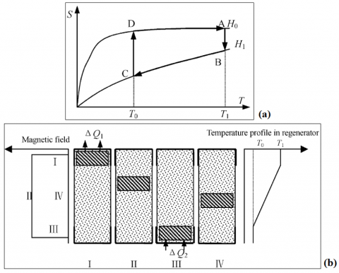
Ericsson cycle consists of two isothermal processes/ stages and two isofield processes as illustrated in Figures 2(a) and 2(b).
Figure 2. (a) The four processes of magnetic Ericsson cycle in T-S diagram. (b) Principle of magnetic Ericsson cycle refrigerator
In the isothermal magnetization process I(A→B in Figure 2(a)), when magnetic field increases from H0 to H1 the heat transferred from magnetic refrigerant to the upper regenerator fluid makes the latter increasing its temperature.
$Q_{a b}=T_{1}\left(S_{a}-S_{b}\right)$ (6)
In the isofield cooling process II (B→C in Figure 2(a)), while magnetic field is kept constant at the maximum value H1, both the refrigerant and the magnet which generates the field move downward to bottom and hence the heat:
$Q_{b c}=\int_{S_{C}}^{S_{b}} T d S$ (7)
is transferred from magnetic refrigerant to regenerator fluid. Then a temperature gradient is set up in the regenerator.
In the isothermal demagnetization process III (C→D in Figure 2(a)), when magnetic field decreases from H1 to H0, the magnetic refrigerant absorbs heat:
$Q_{a b}=T_{0}\left(S_{d}-S_{c}\right)$ (8)
From the lower regenerator fluid. After that the fluid decreases its temperature.
In the isofield heating process IV (D→A in Fig. 2(a)), while the magnetic field has kept constant at the minimum H0, both the magnetic refrigerant and magnet move upward to the top and the regenerator fluid absorbs heat:
$Q_{d a}=\int_{S_{d}}^{S_{a}} T d S$ (9)
To make the Ericsson cycle possess the efficiency of magnetic Carnot cycle, it is required that the heat transferred in two isofield processes Qbc, Qda are equal. For an ideal Ericsson cycle, ‘parallel’ T–S curves are optimal, that is, ΔSM keeps constant in the cooling temperature range.
3.2 Magnetocaloric Brayton cycle
Magnetocaloric Brayton cycle consists of two adiabatic processes and two isofield processes as shown in Figure 3.
The first process (A→B in Figure 3) consists in and adiabatic magnetization, due to magnetic field increasing from H0 to H1, that leads to a temperature increment of ΔTad,AB in the solid refrigerant. With the field kept constant at H1, in the isofield process (B→C in Figure 3) the heat of the area BC14 is transferred from the refrigerant to the hot heat exchanger at temperature TH. In the adiabatic demagnetization (C→D in Figure 3) process the applied magnetic field falls from H1 to H0 and the solid refrigerant reduces its temperature of a quantity ΔTad,CD as a result of magnetocaloric effect. In the isofield process at H0 the heat of the area AD14 is subtracted from the cold heat exchanger at TC. No heat flows from and out of the magnetic refrigerant during the adiabatic magnetization and demagnetization processes.
The Brayton cycle can exhibit optimal performance as well with magnetic refrigerants having parallel T–S curves.
Figure 3. The four processes of magnetic Brayton cycle in S-T diagram
3.3 Magnetocaloric Carnot cycle
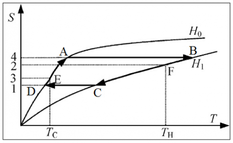
Magnetocaloric Carnot cycle, consists of two adiabatic and two isothermal processes, applied to a magnetic refrigerant, as shown in Figure 4.
An adiabatic magnetization occurs in process 1→2 (Figure 4) and it continues with a further magnetization in stage 2→3, which is now an isothermal magnetization. During this process generated heat is extracted from the system. The next process step, namely 3→4, is an adiabatic demagnetization process. Connecting the system with a heat source leads to an isothermal demagnetization, resulting in process 4→1.
It becomes clear that the Carnot cycle can only be run, if a minimum of four different magnetic fields occurs, through which the magnetocaloric material is moved. In the vertical process 1→2 the alteration of the magnetic field must be applied quickly, not allowing heat to diffuse away or be transported out by convection. In 2→3 the isothermal magnetization requires an alteration of the magnetic field and simultaneous rejection of heat. This process will therefore be slower. The area between (1–2–3–4) represents the work required and the area (1–4–a–b) is related to the thermal cooling energy.
Figure 4. The four processes of magnetic Carnot cycle in T-s diagram
4.1 Cascade systems regenerators
All the cycles previously discussed are ideal cycles. At present the existing magnetocaloric materials could do not show sufficiently wide temperature differences for some frequently occurring refrigeration and heat pump applications. A solution to this problem is to build magnetic refrigerators and heat pumps, which take advantage of cascades. However, both—the regeneration and the cascade systems—show additional irreversibility in their cycles. These leads to lower coefficients of performance.
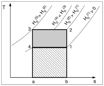
Cascade systems are well known from conventional refrigeration technology. A cascade system is a serial connection of some refrigeration apparatuses. They may be packed into one housing to give the impression of having only a single unit. Each of these apparatuses has a different working domain and temperature range of operation. This can be seen in Figure 5(a) by the decreasing temperature domains of stages I– III. In this figure the cooling energy of stage I (surface: ef14) is applied for the heat rejection of stage II (surface cd23). Analogously, the cooling energy of stage II (surface cd14) is responsible for the heat rejection in stage III. The cooling energy of the entire cascade system is represented by the surface ab14 of the last stage (white domain). The total work performed in the total cascade system is given by the sum of the areas 1234 of all present stages I, II, and III.
Figure 5. Two cascade systems based on the Brayton cycle. In case (a) all stages (I, II and III) are designed to have a different optimally adapted material, whereas in case (b) they are produced with the same material
The magnetocaloric effect is maximal at the Curie temperature. It is large only in the temperature interval around this temperature, with decreasing effect in the case of greater (temperature) differences. It is therefore, advantageous that the operating point of the refrigeration plant and this temperature interval of optimal magnetocaloric effect coincide. If the temperature span of the refrigeration process is too wide, a decrease in efficiency occurs. A solution to this problem is to work with a cascade system, where each internal unit has its own optimally adapted working temperature. Each stage of a cascade system contains a different magnetocaloric material (Figure 5(a)) or it contains the same (Figure 5(b)).
4.2 The regenerators
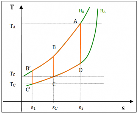
The introduction of the regenerators in a refrigeration system, with reference to magnetic refrigeration, has the purpose to recover heat fluxes involved in Brayton cycle, that otherwise would have gone lost. The approach is particularly needed in room temperature magnetic refrigeration, where the vibrational entropy contribution becomes too high to be neglected. Therefore, a part of the magnetic refrigeration’s cooling capacity is spent to cool the thermal load offered by the crystalline lattice, thus reducing the useful effect of the cycle. As a matter of fact, if a regenerator is added to the system, the heat rejected by the crystalline structure in one of the process of the cycle, is stored and then given back in the other process. By the way, the energy spent to cool the crystalline structure could be utilized effectively to increase of effective entropy change and temperature span [18].
Figure 6. The regeneration effect in the Brayton cycle.
In Figure 6 one can appreciate the effect of the regeneration in Brayton cycle: thanks to the thermal interchange is possible to reach a temperature range TA-TC 'greater than TA-TC, that would occur without regeneration, and a higher entropy change.
It is useful underlining the characteristics proper of the different typologies of regenerator. There are three types of regenerators employable in magnetic refrigerators:
external,
internal,
active.
Heat transferring through external regenerator between the regenerator material (which generally is solid-state) and the magnetic refrigerant is completed by an auxiliary heat transfer fluid.
With internal regenerator solution, the magnetic refrigerant is placed in regenerator together with the regenerator material and heat is transferred directly between themselves so that the regenerator should be in the magnetic field area.
If the regenerator is active, the magnetic material plays the double role of refrigerant and regenerator at the same time. It leads two advantages: both the irreversibility losses, due to the auxiliary fluid, and the losses related to regenerating fluid mixing at different temperature are reduced. Thus the irreversible losses yielded by the second heat transferring in external regenerator or by mixing of the regenerator fluid with different temperature in internal regenerator, can be reduced.
The relative heat capacity between auxiliary fluid and magnetic refrigerant, plays a key role in choosing the best-fitting configuration of regenerator. If the heat capacity of the regenerator’s fluid is higher than refrigerant magnetic material, it is better adopting an internal regenerator, where the temperature span in the regenerator is easily influenced by the fluid mixing. On the contrary case the best choice falls on active magnetic regenerator (AMR), where a high temperature span could be triggered and the requested fluid flow rate, on equal cooling power, is lower than the previous case.
There are several desirable characteristics for the perfect regenerator [19]:
infinite thermal mass compared to the working material being cooled or heated;
infinite heat transfer (a product of thermal conductance multiplied by the contact area) between working material and regenerator mass;
zero void volume;
zero pressure drop for convection of fluid through the regenerator;
zero longitudinal conduction along the regenerator
uniform, linear temperature gradient from the hot end to cold end of the unit.
The irreversible heat losses of the regenerator have a great influence on the performance of the whole magnetic refrigeration system. It has been analyzed the effect of thermal resistances and regenerative losses on the performance of magnetic Ericsson cycle qualitatively [20]. Main irreversible heat losses are:
loss of finite heat transfer between regenerator material and heat transfer fluid;
loss of pressure drop yielded by flow resistance;
thermal conduction along the magnetic material.
loss of mixing of regenerator fluid in the internal regenerator;
loss of heat leakage;
losses of magnetic hysteresis and eddy currents;
loss caused by viscous dissipation in the regenerator fluid;
loss of ‘‘dead volume’’.
In an AMR, some amount of the heat transfer fluid is always in the connecting lines between the beds and the heat exchangers and never cycles both through the beds and the heat exchangers. This trapped heat transfer fluid, commonly referred to as the ‘‘dead volume,’’ is a significant source of inefficiency in active magnetic regenerators [21].
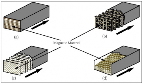
In Figure 7 some typical structural configurations of AMR regenerators are represented. Specifically, they are:
parallel plate configuration;
perforated plate configuration;
grid configuration;
packed bed configuration.
Figure 7. Typical AMR regenerator’s configurations
4.3 Active Magnetic Regenerative refrigerant (AMR) cycle
Barclay [22] firstly introduced the Active Magnetic Regenerative refrigeration cycle, well known as AMR. The innovative idea leads to a new magnetic cycle, different from the previous ones (Carnot, Ericsson, Brayton, or Stirling). It is founded on a magnetic Brayton cycle as shown in Figure 8.
The main innovation consists of introducing the AMR regenerator concept, i.e. the employment of the magnetic material both as refrigerant and regenerator. A secondary fluid is used to transfer heat from the cold to the hot end of the regenerator. Substantially every section of the regenerator experiments its own AMR cycle, according to the proper working temperature. Through an AMR one can appreciate a larger temperature span between the regenerator material and the auxiliary fluid.
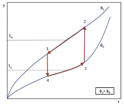
Figure 8. The four processes of AMR cycle in T-s diagram.
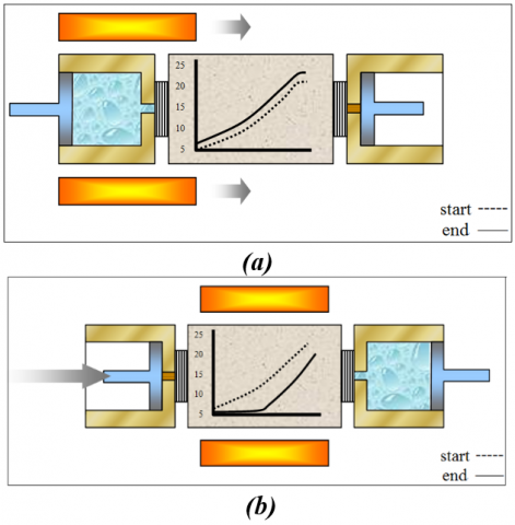
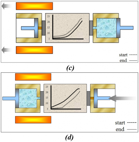
During the entire cycle, the magnetic field induction varies between a minimum value, B0, and a maximum one, B1. The regenerator works between a warm reservoir at TH and a cold one at TC. The AMR cycle consists of four processes. During the magnetization (1→2), the magnetic field is increased adiabatically with no fluid flow, causing the increase of the temperature of the magnetic material due to MCE, as displayed in Figure 9(a). In the cold-to-hot flow process (2→3), visible in Figure 9(b) the secondary fluid blows from the cold to the hot end of the regenerator when the field has kept constant at the maximum value. The fluid absorbs heat from the bed, reaching a temperature above TH and rejects it through the warm heat exchanger. The next process, shown in Figure 9(c), is the adiabatic demagnetization (3→4) where, without any fluid flowing, the magnetic field is removed, and the magnetic material temperature decreases because of the MCE. Finally, the heat transfer fluid flows through the bed from the hot to the cold end (4→1), as Figure 9(d) exhibits, with the applied magnetic field kept fixed at the minimum. The resulting hotter fluid cools the bed and reach a temperature lower than TC. At this stage the secondary fluid absorbs heat from the cold heat exchanger producing a cooling load.
The AMR cycle described in this section has the peculiarity to employ a heat transfer fluid which has alternative motion. Other project solutions could take to slightly modifications of the cycle implementation.
Figure 9. The four processes of AMR cycle
5.1 The criteria for selecting magnetocaloric refrigerants
In terms of the theoretical analyses and the magnetocaloric nature of existing materials, the criteria for selecting magnetic refrigerants for active magnetic refrigerators are given as follows [23, 24]:
the large magnetic entropy change and the large adiabatic temperature change (i.e., the large MCE) at moderate magnetic field;
the large density of magnetic entropy (it is an important factor contributing to the working efficiency of materials);
the small lattice entropy;
nearly zero magnetic hysteresis (it is related to the working efficiency of a magnetic refrigerant material);
very small thermal hysteresis (this is related to the reversibility of the MCE of a magnetic refrigerant material);
small specific heat and large thermal conductivity (these ensure remarkable temperature change and rapid heat exchange);large electric resistance (i.e., the lowering eddy current heating or the small eddy current loss);
high chemical stability and simple sample synthesis route are also required for magnetic refrigerant materials;
no toxic or too expensive elements;
corrosion resistance material;
limited number of elements in the compound in order to facilitate the control of reproducibility;
synthesis process compatible with large-scale production;
instantaneous MCE corresponding to a magnetic field variation;
small volume variation.
5.2 Panorama of the most promising magnetocaloric refrigerants at room temperature
Since Brown [25] first applied ferromagnetic material gadolinium (Gd) in the room temperature magnetic refrigerator, the research field of magnetic refrigeration working materials has been greatly expanded.
The most employed material for the refrigeration at room temperature is gadolinium, a rare-earth metal which exhibits a second order paramagnetic to ferromagnetic transition at its Curie temperature (Tc = 294 K) which exhibits excellent magnetocaloric properties. Gadolinium (Gd) is the only rare earth which orders magnetically near room temperature and is often considered to be a simple Heisenberg ferromagnet, i.e., a representative classical ferromagnet. The paramagnetic to ferromagnetic phase transition is a second-order phase transformation.
There are several reasons why Gd is still considered the benchmark material for magnetic cooling applications: since Gd is considered a classical ferromagnet and it orders near room temperature, it is quite easy to carry out experiments to gain a better understanding of the nature of the paramagnetic to ferromagnetic phase transformation. Second, this transformation has a potentially large practical importance, specifically with regard to magnetic cooling and heating near room temperature.
Recently the magnetic materials undergoing a first-order magnetic transition become the focus after the giant MCE was discovered in GdSiGe alloys.
Gd5(SixGe1-x)4 compounds (where1≤x<0.5) are among the most promising compounds for magnetic refrigeration. Alloys of gadolinium, silicon and germanium, Gd5(SixGe1-x)4 show a First Order Magnetic Transition (FOMT) characterized by a peak of ΔTad and ΔSM much greater than gadolinium ones, but the whole function is quite sharper in Gd5(SixGe1-x)4 alloys. In particular, Gd5(Si2Ge2), which exhibits the larger MCE among Gd5(SixGe1-x)4 compounds and which is named GIANT MagnetoCaloric Effect (GMCE), presents two different phase transitions. At 276 K one can observe in Gd5(Si2Ge2) a FOMT which constitute the MCE highest temperature peak, whereas at 299 K it is possible to appreciate a Second Order Magnetic Transition (SOMT) where, according to it, the material orders paramagnetically. Nevertheless Gd5(Si2Ge2) shows a moderate hysteresis of 2 K [26].
Nowadays a huge part of researchers is orienting its attention on some new alloys of magnetocaloric materials: as a result, many new materials with large MCEs (and many with lesser values) have been discovered, and a much better understanding of this magneto-thermal property has resulted. A number of new magnetocaloric substances with substantial cooling capacity have been discovered: the lanthanide aluminides and the La manganites, some of which have MCEs comparable to Gd between 220 and 290 K; the tunable giant MCE for room temperature range.
The La-Fe binary phase diagram shows an immiscible system, in which no intermetallic compounds form. The addition of small amount of Si or Al allows the formation of a ferromagnetic face-centred-cubic structure; this intermetallic compound exhibits very interesting magnetic behaviour with GMCE. Tuning the temperature transition either by changing the Fe/Si ratio or substituting a different Rare Earth metal for La yielded an almost linear relationship between SM and TC. Moreover, the FOMT changed to a SOMT as temperature increased. A more efficient way to shift Curie temperature to higher temperatures, however, is by partial Co substitution for Fe, as the magnetic moment of Fe is not seriously affected by Co substitution.
Two interesting compounds among La(Fe,Si)13 alloys for magnetic refrigeration at room temperature are: LaFe11.384Mn0.356Si1.26H1.52 [27], which has a first order magnetic phase transition at 290 K, and LaFe13-x-yCoxSiy [28], where the chemical composition of these are LaFe11.06Co0.86Si1.08, LaFe11.05Co0.94Si1.01 and LaFe10.96Co0.97Si1.07, in order to varying the Curie temperature in 275.8÷289.8 K.
MnAs alloys also assume the role of candidates for new magnetic refrigeration materials at room temperature because those compounds have a giant MCE exhibiting at first order magnetic transition; by varying alloy's composition, the Curie temperature could be switched in the range 220÷318 K. Anyway, MnAs shows also a thermal hysteresis that is bad for practical application. Among Mn-based compounds, MnFeP1-xAsx compounds that are stable for 0.15 < x < 0.66 and exhibit interesting magnetic properties associated with a first order metamagnetic transition. The Curie temperature of the alloy increases linearly with the as contents. MnFeP1-xAsx shows a large magnetic entropy change with the same magnitude as Gd5Si2Ge2.
MnFeP0.45As0.55, is an interesting MnAs alloys: it undergoes a FOMT from paramagnetic to ferromagnetic at 307 K (on heating) according to a rapid decrease of the material parameters which changes its Debye temperature and its electronic structure [29]. The first order transition occurs at 302.8 K on cooling, and at 306.6 K on heating. This indicates a thermal hysteresis of 3.8 K. The change in volume at the transition temperature is about 2.2%. The adiabatic temperature change for these compounds is relatively low and the thermal conductivity is significantly lower than that of gadolinium and other magnetic materials.
In this paper all the fundamentals concerning magnetocaloric cooling from the thermodynamic point of view were treated. Many are the cycles that can be employed to structure a magnetocaloric system for cooling or heat pumping. The real bottleneck is located in the development of high efficiency magnetocaloric materials in order to overcome the limits in useful cooling power and maximum working ΔT that, currently, limit the commercialization and therefore the employment of magnetocaloric technology on a large scale.
|
B |
magnetic field induction, T |
|
C |
specific heat, J. kg-1. K-1 |
|
H M |
magnetic field, A.m-1 magnetization, T |
|
Q |
heat, J |
|
S |
entropy, J. kg-1. K-1 |
|
T |
temperature, K |
|
Greek symbols |
|
|
µ0 |
magnetic permeability, H. m-1 |
|
Subscripts |
|
|
C |
Curie |
|
H |
constant magnetic field |
|
M |
constant magnetization |
|
ST |
structural |
[1] Protocol, M. (1987). Montreal protocol on substances that deplete the ozone layer. Washington, DC: US Government Printing Office, 26, 128-136.
[2] Protocol, K. (1997). United Nations Framework Convention on Climate Change. Kyoto Protocol, Kyoto, 19, 497.
[3] EU No 517/2014. European Regulation No 517/2014 on Fluorinated Greenhouse Gases and Repealing Regulation (EC) No 842/2006, 2014, Off. J. Eur. Union.
[4] Aprea, C., Greco, A., Maiorino, A. (2012). An experimental evaluation of the greenhouse effect in the substitution of R134a with CO2. Energy, 45(1), 753-761. https://doi.org/10.1016/j.energy.2012.07.015
[5] Palm, B. (2008). Hydrocarbons as refrigerants in small heat pump and refrigeration systems–A review. International journal of refrigeration, 31(4): 552-563. https://doi.org/10.1016/j.ijrefrig.2007.11.016
[6] Aprea, C., Greco, A., Maiorino, A. (2016). An experimental investigation on the substitution of HFC134a with HFO1234YF in a domestic refrigerator. Applied Thermal Engineering, 106: 959-967. https://doi.org/10.1016/j.applthermaleng.2016.06.098
[7] Mota-Babiloni, A., Navarro-Esbrí, J., Molés, F., Cervera, Á. B., Peris, B., Verdú, G. (2016). A review of refrigerant R1234ze (E) recent investigations. Applied Thermal Engineering, 95: 211-222. https://doi.org/10.1016/j.applthermaleng.2015.09.055
[8] Kitanovski, A., Egolf, P.W. (2006). Thermodynamics of magnetic refrigeration. International Journal of Refrigeration, 29(1): 3-21. https://doi.org/10.1016/j.ijrefrig.2005.04.007
[9] Ožbolt, M., Kitanovski, A., Tušek, J., Poredoš, A. (2014). Electrocaloric refrigeration: thermodynamics, state of the art and future perspectives. International journal of refrigeration, 40: 174-188. https://doi.org/10.1016/j.ijrefrig.2005.04.007
[10] Tušek, J., Engelbrecht, K., Millán‐Solsona, R., Manosa, L., Vives, E., Mikkelsen, L.P., Pryds, N. (2015). The elastocaloric effect: A way to cool efficiently. Advanced Energy Materials, 5(13): 1500361. https://doi.org/10.1002/aenm.201500361
[11] Pecharsky, V. K., Gschneidner Jr, K.A. (1997). Giant magnetocaloric effect in Gd5(Si2Ge2). Physical Review Letters, 78(23): 4494. https://doi.org/10.1103/PhysRevLett.78.4494
[12] Lu, S.G., Rožič, B., Zhang, Q.M. et al. (2010). Organic and inorganic relaxor ferroelectrics with giant electrocaloric effect. Applied Physics Letters, 97(16): 162904. https://doi.org/10.1063/1.3501975
[13] Liu, Y., Infante, I. C., Lou, X., Bellaiche, L., Scott, J.F., Dkhil, B. (2014). Giant room‐temperature elastocaloric effect in ferroelectric ultrathin films. Advanced Materials, 26(35): 6132-6137. https://doi.org/10.1002/adma.201401935
[14] Kitanovski, A., Tomc, U., Poredos, A. (2016). Future developments in magnetocaloric refrigeration and heat pumping. In Proc. of the 7th IIR/IIF International Conference on Magnetic Refrigeration at Room Temperature, THERMAG, 11-14.
[15] Warburg, E. (1881) Magnetische Untersuchungen. Über einige Wirkungen der Coërcitivkraft. Ann. Phys, 13: 141-164.
[16] Aprea, C., Greco, A., Maiorino, A. (2011). A numerical analysis of an active magnetic regenerative cascade system. International Journal of Energy Research, 35(3): 177-188. https://doi.org/10.1002/er.1682
[17] Aprea, C., Greco, A., Maiorino, A., Masselli, C. (2017). A two-dimensional investigation about magnetocaloric regenerator design: parallel plates or packed bed? In Journal of Physics: Conference Series (Vol. 796, No. 1, p. 012018). IOP Publishing. Ferrara, Italy. https://doi.org/10.1088/1742-6596/796/1/012018
[18] Yu, B.F., Gao, Q., Zhang, B., Meng, X.Z., Chen, Z. (2003). Review on research of room temperature magnetic refrigeration. International Journal of Refrigeration, 26(6): 622-636. https://doi.org/10.1016/S0140-7007(03)00048-3
[19] Barclay, J.A. (1994). Active and passive magnetic regenerators in gas/magnetic refrigerators. Journal of Alloys and Compounds, 207: 355-361. https://doi.org/10.1016/0925-8388(94)90239-9
[20] Chen, J., Yan, Z. (1998). The effect of thermal resistances and regenerative losses on the performance characteristics of a magnetic Ericsson refrigeration cycle. Journal of Applied Physics, 84(4): 1791-1795. https://doi.org/10.1063/1.368349
[21] Lawton Jr, L.M., Zimm, C.B., Jastrab, A.G. (1999). U.S. Patent No. 5,934,078. Washington, DC: U.S. Patent and Trademark Office.
[22] Barclay, J.A. (1982). The theory of an active magnetic regenerative refrigerator. NASA STI/Recon Technical Report N, 83, 34087.
[23] Phan, M.H., Yu, S.C. (2007). Review of the magnetocaloric effect in manganite materials. Journal of Magnetism and Magnetic Materials, 308(2): 325-340. https://doi.org/10.1016/j.jmmm.2006.07.025
[24] Aprea, C., Greco, A., Maiorino, A., Masselli, C. (2015). A comparison between rare earth and transition metals working as magnetic materials in an AMR refrigerator in the room temperature range. Applied Thermal Engineering, 91: 767-777. https://doi.org/10.1016/j.applthermaleng.2015.08.083
[25] Brown, G.V. (1976). Magnetic heat pumping near room temperature. Journal of Applied Physics, 47(8): 3673-3680. https://doi.org/10.1063/1.323176
[26] von Moos, L., Bahl, C.R.H., Nielsen, K.K., Engelbrecht, K. (2014). The influence of hysteresis on the determination of the magnetocaloric effect in Gd5Si2Ge2. Journal of Physics D: Applied Physics, 48(2): 025005. https://doi.org/10.1088/0022-3727/48/2/025005
[27] Morrison, K., Sandeman, K.G., Cohen, L.F. et al. (2012). Evaluation of the reliability of the measurement of key magnetocaloric properties: A round robin study of La (Fe, Si, Mn) Hδ conducted by the SSEEC consortium of European laboratories. International Journal of Refrigeration, 35(6): 1528-1536. https://doi.org/10.1016/j.ijrefrig.2012.04.001
[28] Bjørk, R., Bahl, C.R.H., Katter, M. (2010). Magnetocaloric properties of LaFe13− x− yCoxSiy and commercial grade Gd. Journal of Magnetism and Magnetic Materials, 322(24): 3882-3888. https://doi.org/10.1016/j.jmmm.2010.08.013
[29] de Oliveira, N.A., von Ranke, P.J. (2005). Theoretical calculations of the magnetocaloric effect in MnFeP0. 45As0. 55: A model of itinerant electrons. Journal of Physics: Condensed Matter, 17(21): 3325. https://doi.org/10.1088/0953-8984/17/21/025