Stefano Aneli | Roberta Arena | Antonio Gagliano*
OPEN ACCESS
This paper focuses on the possibility to improve the performances of the photovoltaic (PV) modules through the passive cooling of photovoltaic cells, using phase change materials (PCMs.) In particular, the use of two organic PCM to reduce the temperature rise in PV module has been investigated by numerical simulations. A two-dimensional fluid dynamic simplified model has been developed in Ansys Fluent software to characterize the thermal behavior of the PV module where the PCM is incorporated (PV-PCM), as well as for a benchmark PV module. The results show that PCMs allow to achieve better performance if compared to PV modules without PCM, with an increase in terms of peak electric power even higher than 9% and in terms of daily energy of about 5% all year round, except for winter. Moreover, the dynamic analysis performed for several days allows to evaluate the effective performance of the PV-PCM, taking into account the real degree of solidification achieved during the night. This analysis shows that the use of PCM with low melting temperature does not guarantee complete solidification during the night and this limits its effectiveness during the day.
PCM, PV performances, cells temperature, efficiencies, solidification/melting
As the rise in the temperature of photovoltaic (PV) cells leads to a decrease in the solar to electricity conversion efficiency, many methods have been planned to cool the PV cells [1, 2], as well as for increasing their efficiency [3].
They may be differenced into two major categories, active cooling and passive cooling. The active cooling techniques requires energy to operate, while passive cooling techniques are preferable because they do not require energy supply to operate and less maintenance.
One of the main passive cooling techniques is the use of phase change materials (PCM).
PCMs may enable the PV module to operate with good solar electrical conversion efficiency as they absorb energy as latent heat at a constant phase transition temperature. So, the use of PCM creates a temporary shift in temperature rise [4].
PCM can temporarily store renewable or cheap heat or cold respectively and make it available again later when it is needed, so they may be used in combination with electrical storage [5, 6].
The numerical model and experimental tests developed in [7] has highlighted that a tank of 40 mm of PCM attached to the rear of the PV panel allows controlling the temperature of PV for about 150 min under a solar 2 insolation of 750 W m−2.
Usually, for PV-PCM systems, the melting temperature is about 20–40 °C. Using a transitory one-dimensional energy balance model, Kibria et al. [8] studied the effect of the variation of the melting point, obtaining an increase in the performance of the PV-PCM of 5% compared to the standard PV.
It is a fact that the energy flow due to convection inside the melted PCM affects the system’s performance significantly [9]. A CFD analysis performed keeping the air temperatures and solar radiation constant, showing that the greatest electrical producibility is obtained with PCMs that have fusion temperatures close to the air temperatures [10]. Several PCMs analyzed in the paper [11] shown that the increase in latent heat capacity improves the PV performance.
The optimum depth of PCM container to keep the PV cool has been calculated under various daily solar radiation levels in the paper [12]. This study highlights that PCM having a lower melting temperature (near to ambient) can maintain the PV at a lower temperature. Larger quantity PCM of is necessary as ambient temperature increases the optimum depth of PCM container increases and, as wind velocity increases the optimum depth decreases. A very important topic is the study of a PV-PCM performance under real irradiance and environment temperature.
A numerical study using CFD simulation was developed in COMSOL to compare the PV temperature with different PCMs varying solar irradiation and ambient temperature, for two summer days [13]. The results of that study show that the PCM works differently over the two days, even if the working conditions do not change as the PCM does not complete the solidification process overnight due to its low melting temperature. This phenomenon highlights that neglect of the solidification process will lead to inaccurate simulation results, which is an aspect that is not yet deeply considered in the literature.
However, there is a scarcity of both theoretical and experimental studies on PV-PCM system in the Mediterranean area, where more important is the importance to maintain cool the temperature of the PV cells.
To cover this lack of knowledge, this study proposes an unsteady CFD study on a PV module equipped with two different types of PCM installed in Catania (IT).
The daily variation of the cell temperatures, as well as the electrical performance of the PV-PCM module, are compared with that one of a conventional PV module considering the winter solstice, autumn equinox and summer solstice.
To simulate non-steady state conditions a novel CFD model has been built that allows taking into account of real weather conditions, such as the hourly daily solar irradiation environment temperature, and wind velocity.
The simulations are extended for two days, so in this way, it is possible to verify the actual degree of PCM solidification/melting that occurs during such period.
In the last 15 years, scientists are using PCMs in many and varied applications, the interest in these materials is born because of the possibility to store a remarkable amount of energy maintaining the temperature at a constant value.
Ideal PCMs must have a large latent heat of fusion, usually, it is good to have it greater than 150 J/g, because the greater the latent heat the less the quantity of material needed to store a certain amount of energy high thermal conductivity, the melting temperature must be in the practical range of operations, low cost, non-toxic and non-corrosive. Consequently, it is convenient to have PCM as dense as possible [14]. Another important parameter is the thermal conductivity which represents the ability of a substance to transmit heat, therefore the higher the thermal conductivity the faster the heat transfer. Besides, the solidification and melting temperature must be the same or in any case with small differences, many PCMs freeze or melt in an interval of different degrees and therefore will present thermal hysteresis, which therefore leads to a loss of energy in a system. Furthermore, the latent heaters of the PCM cannot be exploited if the thermal hysteresis exceeds the operating temperature range. Finally, PCMs must be chemically stable, as they are subject to different melting/freezing cycles and this could affect melting and freezing points and their latent heat.
PCMs applications are based on the principle that during solidification PCM emits energy avoiding a sharp reduction in temperature, on the other hand, if the PCM is in solid form, it can subtract a certain amount of heat avoiding overheating. In the case of constant specific heat capacities for each phase, the temperature field, which during the phase change is constant, can be defined as:
$T=\left\{\begin{array}{c}
\frac{E}{c_{s}} T<T_{m} \quad \text { (solid phase) } \\
T_{m} T>T_{m} \text { and } 0<E<H \text { (melt zone) } \\
T_{m}+\frac{(E-H)}{c_{l}} T>T_{m} \text { and } E>H \text { (liquid ph.) }
\end{array}\right.$ (1)
The use of PCM gives better results in those places where there is a good difference in temperature between day and night, in fact in this way it is possible to guarantee a complete solidification of the PCM overnight and the following day its latent heat can be fully exploited. Obviously, to achieve this, it is necessary to carefully choose the type of PCM to be used and therefore its melting temperature.
Paraffins and in general organic PCMs are more applicable to PV system cooling, as they have excellent thermal stability with regards to cycling, which is important in a system that heats up and cools down daily [15].
This study compares the thermal behaviour and the electrical yields of a conventional photovoltaic module (PV) with that one of the same PV module equipped with Phase Change Material (PV-PCM).
The efficiency of PV cells is strongly influenced by the temperature of the cells themselves, temperatures increasing cause the decrease of the efficiency. Furthermore, the layers that make up the panel have a very small thickness and therefore small masses and low thermal inertia. Thus, as soon as the solar irradiation grows, they heat up quickly, making production efficiency decline [16].
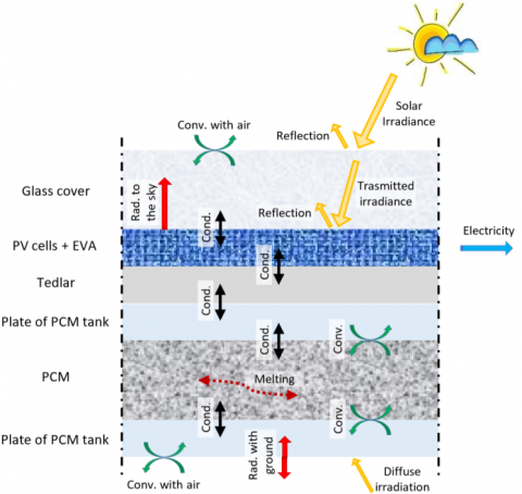
One way to keep the module temperature low for longer is to use Phase Change Materials (PCM). In a PV-PCM module, the variation of the temperature of the cells is determined by the behaviour of the PCM, which during the melting process absorb heat without changing its temperature. Figure 1 shows the main thermal fluxes for the PV-PCM, which can be summarized as follows:
Figure 1. Energy fluxes in PV-PCM module
The container filled with the PCM is constituted by a tank constituted by aluminium sheets.
3.1 CFD simulation
The study of the PV-PCM module through an unsteady state Computational Fluid Dynamics (CFD) analysis allows evaluating the heat fluxes which occur into the PV module taking into account of the effective thermal inertia of the system, as well as of the melting process.
In this research, the ANSYS Fluent software [17] has been used for simulating the thermal behaviour of both a PV-PCM and a conventional PV module, under dynamic conditions.
The PV panels are simulated considering a bi-dimensional geometry being a length of 1.0 m, which allows to include all the layers that compose the PV module. The mesh is of structured type, composed of only quadrangular elements, where the smallest has size 10-4 x 3∙10-4 m and the largest has size 7∙10-4 m x 8∙10-4 m.
To check the quality of the mesh the report orthogonally quality and the ortho skew have been detected finding values of 1.0 and 0.0, which indicates that the mesh has a high quality.
The weather conditions (air temperature, solar irradiance and wind velocity) are implemented through User Defined Functions (UDFs), which are assembled for the specific case. The incident solar irradiation used for defining the equations of thermal balance (Geff) is calculated using Eq. (2).
$G_{e f f}=G \cdot \tau_{g} \cdot \alpha_{p V} \cdot\left(1-\eta_{e l}\right)$ (2)
where, G is the total irradiance on the plane of the module, τg is the transmission coefficient of irradiation through the glass cover, αPV represents the absorption coefficient of PV cells and ηel is the electrical efficiency of the module, calculated using Eq. (3).
$\eta_{e l}=\eta_{\operatorname{src}}\left[1-\gamma\left(T_{P V}-T_{S T c}\right)\right]$ (3)
where, ηSTC and TSTC are respectively the efficiencies and the temperature at Standard Test Condition and γ is the thermal coefficient of the PV panel.
The radiative exchanges between the front of the PV module and the sky-dome have been implemented with a specific UDF and are calculated using the Stefan-Boltzmann law [18]:
$\dot{q}_{r a d, g-s k y}=\sigma_{0} \cdot \varepsilon \cdot F\left(T_{g}^{4}-T_{s k y}^{4}\right)$ (4)
where, σ0 is the Stefan-Boltzmann constant, ε represent the emissivity of the glass and F is the view factor calculated with Eq. (5), where β is the tilt angle of the PV module.
$F=\frac{1+\cos \beta}{2}$ (5)
The radiative exchanges between the rear part of the panel and the ground are calculated once again through Eq (4), where the glass is replaced with the back of the panel and the sky with the ground.
According to the paper [19], the coefficient of convective flux with the air is calculated using Eq. (6), where w represents the wind velocity expressed in m/s.
$h=5.7+3.8 \cdot w$ (6)
3.2 Energy performance
The electrical efficiency of the photovoltaic panel calculated by Eq. (3), is a function of the temperature of the cells, which in turns is calculated through the CFD simulation.
Thus, the electrical power (Pel) produced by the PV panel is calculated from the irradiance on the collector plane G, the surface of the PV cells and the electrical efficiency:
$P_{e l}=\eta_{e l} \cdot A_{P V} \cdot G$ (7)
Finally, the electric energy product is evaluated as:
$E_{e l}=\int P_{e l} \cdot d t$ (8)
The scenarios analyzed refer to a PV module with and without PCM container attached at its rear.
The reference PV module has an STC efficiency (ηSTC) of 17% and the thermal coefficient (γ) of 0.4%/K.
The features of the layers that compose the PV module are specified in Table 1.
Table 1. Properties of the layers that make up the PV and PV-PCM modules
|
|
C J/kgK |
k W/mK |
ρ kg/m3 |
Thickness mm |
|
GlassTable size |
500can be |
1.8 |
3000 |
4.0 |
|
EVA |
2090 |
0.35 |
960 |
0.5 |
|
Silicon |
677 |
148 |
2330 |
0.3 |
|
Tedlar |
1250 |
0.2 |
1200 |
0.1 |
|
Aluminium |
903 |
211 |
2675 |
4.0 |
The PCM’s container, composed of two aluminium sheet, has a thickness of 6.0 cm. Such thickness is suggested by Ma et al. [11] when the solar radiations and outdoor temperatures are high, and the wind velocities are low.
Two different types of PCM are investigated in this study: Rubitherm 28 HC and Rubitherm 35 HC. These PCMs have chosen since they have good stability and high capacity to accumulate energy during the solidification/melting transformation. Table 2 shows the main properties of the PCMs used.
Table 2. Properties of the used PCM materials
|
|
|
Rubitherm28 HC |
Rubitherm 35 HC |
|
TmeltingTable size |
°Ccan be |
27-29 |
34-36 |
|
Tcongeling |
°C |
29-27 |
36-34 |
|
H1 |
kJ/kg |
250 |
240 |
|
CP |
kJ/kgK |
2.00 |
2.00 |
|
ρsolid |
kg/l |
0.88 |
0.88 |
|
ρliquid |
kg/l |
0.77 |
0.77 |
|
k |
W/mK |
0.20 |
0.20 |
Notes: 1 Combination of latent and sensible heat in a temperature range, respectively for Rubitherm 28 HC and 35 HC from 21°C to 36°C and from 27°C to 42.
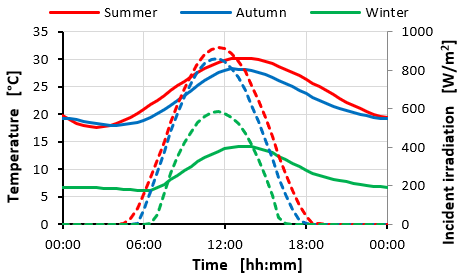
The simulations are carried out considering the two investigated PV modules, with and without the addition of the PCM, located in Catania (IT) (37° 30' 0" N - 15° 6' 0" E). It was assumed that the modules facing south, with a tilt angle of 30 degrees. The weather data, solar irradiation and air temperature were derived from the PV-GIS database [20] considering clear days.
All the analyses are developed considering three annual “representative” days: the winter solstice, autumn equinox and summer solstice.
Figure 2 shows the outdoor temperature (continuous line) and the incident solar irradiation (dashed line) during those three days.
Figure 2. Weather data on the summer solstice, autumn equinox and winter solstice
As regards the wind speed it is assumed constant and equal to 1.0 m/s.
This section compares the thermodynamic behaviours and the energy performance of the conventional PV module with the two PV-PCM modules, equipped one with Rubitherm RT 28 HC (PV-RT28) and the other with Rubitherm RT 35 HC (PV-RT35).
To properly evaluate the effective performances of a PV-PCM module it is mandatory taking into account the degree of solidification achieved by the PCM during the night. Thus, the analysis is conducted for a simulation time of 48 h.
In the following, the results showed are referred to the second day of simulation.
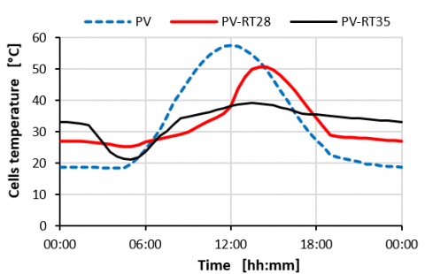
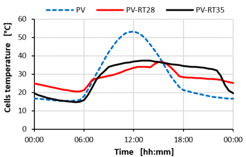
Figure 3 shows the comparisons of the temperature of the photovoltaic cells obtained for the three PV-configurations analyzed during the summer solstice.
Figure 3. PV cells temperature during the summer solstice
It is evident that the attachment of the PCMs in the PV-module allow decreasing of the cell temperatures. It can be noted that the PV-RT35 leads to attaining a reduction of the cell temperature during the whole day, up to a maximum of 20°C at midday. PV-RT28 shows the same or even higher reduction of temperature in the first half of the day, then about at noon the temperature raises abruptly as the RT28 loses its capacity to store the heat, the liquefaction process is completed. The highest temperature of the cells PV-RT28 is 8 °C lower than the maximum temperature touched by the conventional PV module. However, in the second part of the afternoon, after 16:30 for the PV-RT35, and at least one hour before for the PV-RT28, the cell temperatures are higher than that one of the conventional PV module.
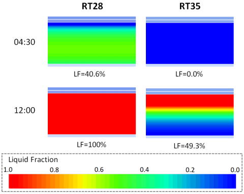
Figure 4 shows the rate of liquefaction of the two PCMs at 4:30 and 12:00.
Figure 4. Liquid fraction on the summer solstice
Figure 5. PV cells temperature profile on the autumn equinox
Figure 6. PV cells temperature profile on the winter solstice
It can be observed that at midnight the RT28 is completely melted otherwise, the RT35 has a liquid fraction of 49.3%. Moreover, RT35 works all day, reaching the maximum liquid fraction of 93.8% at 16:30. Finally, is important to note, that RT28 does not solidify completely overnight, which reaches the lowest liquid fraction of 40.6% at 4:30, while RT35 solidifies completely during the night.
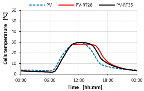
Figures 5 and 6 depict the temperature of the cells respectively for the autumn equinox and winter solstice.
On the autumn equinox, the lower outdoor temperature and solar irradiation represent almost ideal conditions for the operation of PV-PCM equipped with RT28.
The PV-RT28 module operates effectively for all the daily hours by keeping its temperatures lower than the other configurations. Otherwise, RT35 is less effective in cooling the panel, PV-RT35 reaches temperatures higher than PV- RT28PCM. This reversal of behaviour is due to the difficulty for RT35 in reaching the solid/liquid transition temperature for these weather conditions. Anyway, also in this period of the year, the conventional PV-module operates at temperatures higher than both PV-PCM modules. Actually, as in the summer, in the last part of the day, the conventional PV module has lower temperatures than both PV-PCM modules, but in that period of the day the solar radiation is very low and, consequently, such drawbacks have scarce relevance.
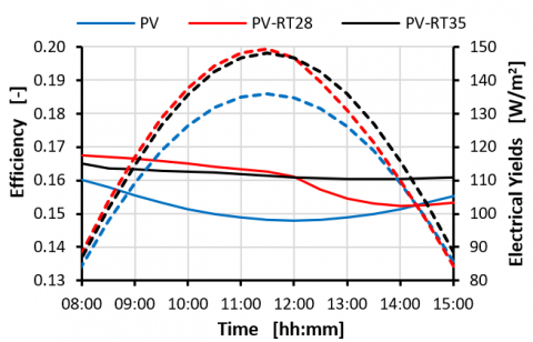
Figure 7. Efficiency and electrical power on the summer solstice
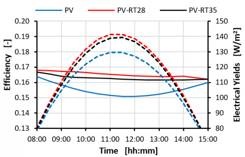
Figure 8. Efficiency and electrical power on the autumn equinox
Results in Figure 6 highlights that on the winter solstice, there is no remarkable difference among the cell’s temperature of the three module configurations. Indeed, the PV cells of a conventional module are lower than 30°C, so the RT35 do not melt, while the PV-RT28 keeps its temperatures at about 28°C, which is the melting point of this PCM. In the last part of the day, it’s possible to notice again an increase in temperature of the PV-PCM modules, due to the increase of the thermal resistance of the PV-PCM modules that delayed the cooling of the PV cells.
Figures 7 and 8 depict the electrical efficiency (continuous lines) and the electrical power (dashed lines) during the summer solstice and the autumn equinox.
The results obtained on the winter solstice are not shown since the efficiency and electrical power are very similar for all the three scenarios due to the very similar cell temperatures.
As shown in Figure 7 the conventional PV module has efficiency and power production lower than both PV-RT28 and PV-RT35 modules. In particular, on the summer solstice in the first part of the day, the PV-RT28 has the highest efficiency, close to ηSTC, while after midday due to exhaustion of PCM work, the efficiency decreases quickly.
Otherwise, the PV-RT35 maintains fairly high efficiency throughout the day, greater than 16%. This trend is repeated for electrical power production it depends on the available solar irradiation and electrical efficiency. Globally, the use of PCMs allows an increase in power production greater than 10.00 W/m2, which is about 10%, during peak hours.
On the autumn equinox, the conventional PV module once again attains the lowest efficiency and power production are the smallest using. In this case, the cell temperatures of the two PV-PCMs modules are very similar during the whole day. So, it is not repeated the decrease of efficiency for the PV- RT28, that was observed after midday on the summer solstice. On this day the presence of PCMs allows an increase in power production during the peak hours of approximately 9.1% and 7.5% respectively using RT28 and RT35. On the winter solstice, as can be deduced from the temperature of the cell in figure 6, there are no remarkable differences between the three PV module, neither in electrical efficiency nor in electrical power.
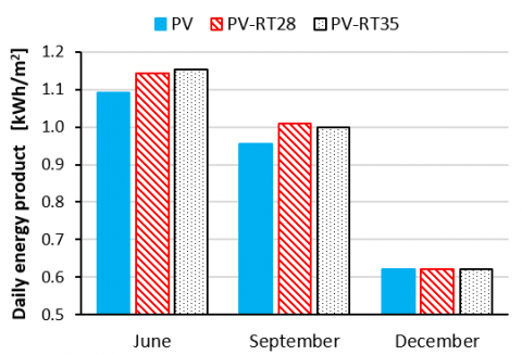
Figure 9 reports the daily electrical yields on the three analyzed days for the three PV-module configurations.
Figure 9. Daily electrical yields
These results reflect what has been already highlighted examining the daily profile of electrical efficiency and power production. The daily electrical yields values, on the winter solstice, are almost the same for the three PV-module configurations, whereas on autumn equinox and summer solstice the lowest daily yields occur in the case of PV-module. The implementation of PCMs improves the performances of PV-modules both on the summer solstice and autumn equinox. On the summer solstice, the daily electrical yields rose by 4.6% using RT28 and by 5.6 % using RT35. Otherwise, on the autumn equinox, this PV- RT28 is the system which has the highest energy production with an increase of about 5.7%, respect to the conventional PV-module, whereas PV- RT35 allows achieving an increase of the daily energy produced of about 4.4%. This finding highlights the importance to carefully choose the type of PCM looking to the climatic conditions of the site of interest. In particular, an important element that has to be observed is the liquefaction temperature of the PCM, and also its complete solidification during the night.
In this study, through CFD analysis, the thermal behavior and the electrical performance of PV-PCM module equipped with two different types of PCM have been evaluated and their performances are compared with that one of a conventional PV module under the same operative conditions.
Using the Fluent simulation software, a model capable of simulating the transfer of heat, mass and momentum of a PCM connected behind a photovoltaic module was developed.
The analyzes were carried out considering the weather conditions of the city of Catania (IT) for different periods of the year.
The simulations were carried out for several consecutive days in such a way to not overlook the actual degree of solidification obtained during the night.
The results of simulations highlight that the use of PCM allows an increase in electrical performance compared to the conventional PV module except on the winter solstice when the cell temperatures and therefore the photovoltaic efficiency are very similar for all the configurations studied.
In detail, the adoption of PV-PCMs allows an increase in terms of peak electric power even higher than 9% compared to PV modules without PCM and an increase of the daily energy yield of about 5.5%.
In general, the use of RT28, which has melting temperatures lower than RT-25 improves the efficiency thanks to its globally greater cooling effect.
However, during the summer days, during very hot days the RT28 runs out of its functionality and the RT-35 perform better in particular after midday. This is also due to the difficulty of solidifying completely during the night for RT 28.
Therefore, it is necessary to carefully choose the type of PCM to be used, observing the climatic conditions of the site of interest throughout the year.
This research is funded by “the Notice 12/2017 for financing the Ph.D. regional grant in Sicily” as part of Operational Program of European Social Funding 2014-2020 (PO FSE 2014-2020).
This work was also financed by the University of Catania within the project "Piano della Ricerca Dipartimentale 2016–2018" of the Department of Electric, Electronics and Computer Engineering of the University of Catania.
|
C |
specific heat, J. kg-1. K-1 |
|
E |
energy, J |
|
F |
dimensionless view factor |
|
G |
solar irradiation, W. m-2 |
|
H |
latent heat, J. kg-1 |
|
H |
convection coefficient, W. m-2. K-1 |
|
LF |
dimensionless liquid fraction |
|
K |
Thermal conductivity, W. m-1. K-1 |
|
P |
power, W |
|
$\dot{\mathrm{q}}$ |
heat flux, W. m-2 |
|
T |
temperature, °C |
|
w |
wind speed, m. s-1 |
|
Greek symbols |
|
|
a |
dimensionless absorption coefficient |
|
b |
tilt angle, rad |
|
γ |
thermal coefficient, K-1 |
|
ε |
dimensionless emessivity |
|
η |
dimensionless, efficiency |
|
ρ |
density, kg. m-3 |
|
σ0 |
Stefan-Botzmann costant, W. m-2. K-4 |
|
τ |
dimensionless transmission coefficient |
|
Subscripts |
|
|
eff |
effective, available |
|
el |
electrical |
|
g |
glass cover |
|
l |
liquid phase |
|
m |
melting |
|
PV |
photovoltaic cells |
|
rad |
radiative flux |
|
s |
solid phase |
|
sky |
sky dome |
|
STC |
standard test conditions |
[1] Zubeer, S.A., Mohammed, H.A., Ilkan, M. (2017). A review of photovoltaic cells cooling techniques. In E3S Web of Conferences, 22: 00205. https://doi.org/10.1051/e3sconf/20172200205
[2] Siecker, J., Kusakana, K., Numbi, B.P. (2017). A review of solar photovoltaic systems cooling technologies. Renewable and Sustainable Energy Reviews, 79: 192-203. https://doi.org/10.1016/j.rser.2017.05.053
[3] Scavo, F.B., Tina, G.M., Gagliano, A., Nižetić, S. (2020). An assessment study of evaporation rate models on a water basin with floating photovoltaic plants. International Journal of Energy Research. https://doi.org/10.1002/er.5170
[4] Atkin, P., Farid, M.M. (2015). Improving the efficiency of photovoltaic cells using PCM infused graphite and aluminium fins. Solar Energy, 114: 217-228. https://doi.org/10.1016/j.solener.2015.01.037
[5] Gagliano, A., Nocera, F. (2017). Analysis of the performances of electric energy storage in residential applications. International Journal of Heat and Technology, 35(S1): S41-S48. https://doi.org/10.18280/ijht.35Sp0106
[6] Buonomo, B., Cirillo, L., Diana, A., di Pasqua, A., Ercole, D., Fardella, V., Manca, O., Nardini, S. (2020). Thermal Energy Storage Systems, 64: 39-44. https://doi.org/10.18280/ti-ijes.640108
[7] Huang, M.J., Eames, P.C., Norton, B. (2004). Thermal regulation of building-integrated photovoltaics using phase change materials. International Journal of heat and mass transfer, 47(12-13): 2715-2733. https://doi.org/10.1016/j.ijheatmasstransfer.2003.11.015
[8] Kibria, M.A., Saidur, R., Al-Sulaiman, F.A., Aziz, M.M.A. (2016). Development of a thermal model for a hybrid photovoltaic module and phase change materials storage integrated in buildings. Solar Energy, 124: 114-123. https://doi.org/10.1016/j.solener.2015.11.027
[9] Kant, K., Shukla, A., Sharma, A., Biwole, P.H. (2016). Heat transfer studies of photovoltaic panel coupled with phase change material. Solar Energy, 140: 151-161. https://doi.org/10.1016/j.solener.2016.11.006
[10] Khanna, S., Reddy, K.S., Mallick, T.K. (2017). Performance analysis of tilted photovoltaic system integrated with phase change material under varying operating conditions. Energy, 133: 887-899. https://doi.org/10.1016/j.energy.2017.05.150
[11] Ma, T., Zhao, J., Han, J. (2017). A parametric study about the potential to integrate phase change material into photovoltaic panel. Energy Procedia, 142: 648-654. https://doi.org/10.1016/j.egypro.2017.12.107
[12] Stritih, U. (2016). Increasing the efficiency of PV panel with the use of PCM. Renewable Energy, 97: 671-679. https://doi.org/10.1016/j.renene.2016.06.011
[13] Nouira, M., Sammouda, H. (2018). Numerical study of an inclined photovoltaic system coupled with phase change material under various operating conditions. Applied Thermal Engineering, 141: 958-975. https://doi.org/10.1016/j.applthermaleng.2018.06.039
[14] Farid, M.M., Khudhair, A.M., Razack, S.A.K., Al-Hallaj, S. (2004). A review on phase change energy storage: materials and applications. Energy conversion and management, 45(9-10): 1597-1615. https://doi.org/10.1016/j.enconman.2003.09.015
[15] Gibbs, B.M., Hasnain, S.M. (1995). DSC study of technical grade phase change heat storage materials for solar heating applications (No. CONF-950336-). American Society of Mechanical Engineers, New York, NY (United States).
[16] Tina, G.M., Gagliano, A. (2016). An improved multi-layer thermal model for photovoltaic modules. In 2016 International Multidisciplinary Conference on Computer and Energy Science (SpliTech), 1-6.
[17] Ansys, I.N.C. (2020). ANSYS FLUENT user’s guide. Canonsburg, PA.
[18] Gagliano, A., Aneli, S. (2020). Analysis of the energy performance of an Opaque Ventilated Façade under winter and summer weather conditions. Solar Energy, 205: 531-544. https://doi.org/10.1016/j.solener.2020.05.078
[19] Skoplaki, E., Boudouvis, A., Palyvos, J. (2008). A simple correlation for the operating temperature of photovoltaic modules of arbitrary mounting. Solar Energy Materials and Solar Cells, 92(11): 1393-1402. https://doi.org/10.1016/j.solmat.2008.05.016
[20] https://ec.europa.eu/jrc/en/pvgis, accessed on 20 March 2020.