OPEN ACCESS
Designers of heat exchangers are regularly searching for new methods that enhance the heat transfer efficiency. A possible substitute of the conventional fins is the use of open-cell metal foams. Low density, good rigidity, high thermal conductivity and huge value of surface/volume ratio represent the best characteristics of porous media. For these features, metal foams are used in several applications such as heat exchangers, fuel cells, heat sinks and solar thermal plants. The need to create new systems in reduced volumes led to the adoption of the aluminum foams for their great specific area surface that allows to have compact heat exchanger characterized by a high thermal performance.
A numerical investigation has been accomplished to analyze the thermal and fluid dynamic behavior of a tubular heat exchanger partially filled with aluminum foam. The Darcy – Brinkman - Forchheimer flow model and the thermal non-equilibrium model (LTNE) for the energy are applied to carry out two-dimensional simulations on the metal foam heat exchanger. The foam has a porosity and (number) pores per inch respectively equal to 0.935 and 20. The heat exchanger is analyzed for different air flow rates and a fixed surface tube temperature. The results are given as average and local heat transfer coefficient evaluated on the external surface of the tubes. Furthermore, the local air temperature profiles in the smaller cross section, between two consecutive tubes are given. Finally, the Energy Performance Ratio (EPR) is evaluated in order to demonstrate the thickness of metal foam that improve the system performances.
aluminum foam, heat exchanger, heat transfer enhancement, partially filled
The industrial world pays particular attention to new techniques that can guarantee an increase in the efficiency of several plants. At the same time, the research is being carried out so that these new techniques cannot increase the risks for the world reducing their negative effects on the environment. Recently, applications of metal foams are employed to improve the heat transfer and consequently energy efficiency of the components. In fact, these materials are generally applied in many industrial fields such as heat exchangers [1], fuel cells, solar power systems [2], heat sinks [3], automotive thermoelectric generator [4], liquefied natural gas system [5], latent thermal energy storage [6].
A review of the literature on heat transfer improvement due to the use of metal foams in a heat exchanger was accomplished by Mahjoob and Vafai [1]. The foam’s morphology influences the thermal and fluid dynamic performance of metal foam heat exchangers, as demonstrated by Huisseune et al. [7].
Kim et al. [8] experimentally analized the influence of the porous fins characterized by different porosity and PPI on the pressure drop and heat transfer in plate-fin heat exchangers. The authors found that the heat transfer was better respect to the case without foam; on the other hand, the porous medium caused a higher pressure drop. An experimental study of thermal and fluid dynamic behavior in a compact heat exchanger with an aluminum foam was carried out by Cicala et al. [9]. Three metal foams were employed, characterized by 10, 20 and 30 PPI and porosity equal to 0.95. The results showed that the maximum heat transfer occurred with the metal foam with a PPI equal to 20.
Several systems of tubes wrapped by metal foam was studied by Chumpia and Hooman [10] experimentally. Several cylinders, characterized by different thicknesses of the aluminum foam, were examined in two-row and three-row bundles to judge their thermo-hydraulic performances. The effects of foam thickness and the row number were estimated. An annular finned tube bundle with the same number of row was employed as sample to do the comparison. The results showed that the second and third rows in the bundle were characterized by a heat exchange major than the first row. The foam bundle was characterized by a friction factor 3 to 6 times larger than that of the finned bundle.
The porous media have been studied using also analytical solutions. Xu et al. [11] carried out an analytical study about the local thermal equilibrium (LTE) model and the local thermal non equilibrium (LTNE) model. The results showed that the heat transfer coefficient in LTE hypothesis is greater than that of LTNE model; furthermore, LTNE model becomes more important when the porosity is low, the difference between the thermal conductivity of the fluid and solid phases is large and the PPI is low. The thermal and fluid dynamic performance of parallel-plate heat exchangers partially filled with foams was analyzed by Lu et al. [12] analytically. The effects of different parameters- such as porosity, pore density, thickness of metal foams- on the system behavior were studied.
The need to have more and more information about the behavior of heat exchangers comes from their numerous applications such as energy conservation and conversion. Several numerical investigations were accomplished in order to estimate the effects of metal foams presence in heat exchange system. Odabaee et al. [13] carried out a numerical study to evaluate the heat transfer efficiency of a cylinder wrapped by metal foam in cross-flow. A comparison was carried out respect to a finned-tube heat exchanger; the results demonstrated that the metal foam cylinder was characterized by a higher heat transfer with an adequate excess of pressure drop. A heat exchanger with porous graphite foam for vehicle cooling was numerically investigated by Lin et al. [14]. Four different arrangements of foams were analyzed in order to evaluate the thermal and fluid dynamic behavior. The results demonstrated that the best configuration was the one with wavy corrugated characterized by a low pressure drop and a high thermal efficiency. A numerical study on heat transfer inside a metal foam was conducted by Zafari et al. [15]. A real geometry was used for the construction of the computational mesh. The results demonstrated that the pressure drop decreased with increasing of the porosity; moreover, the thermal equilibrium between fluid and the solid phases existed for a little size of the porous media.
Alhusseny et al. [16] investigated numerically a double-pipe heat exchanger partially filled with high porosity metal foam and rotating coaxially. The heat transfer improvement was obtained by an active method and a passive method. The active method was the use of a secondary flow near to the surface with metal foam guiding vanes; on the other hand; the passive method was the cover by metal foam of the conducting surface. Several parameters were considered to evaluate the system, like the operating conditions, the arrangement of the guiding vanes, and the geometrical and thermal characteristics of the foam. The rotating porous vanes caused the vortex and so the fluid particles swirled. For this reason, the heat exchange surface changed continually; moreover, the boundary layer became thinner near to the conducting surface. A new Kelvin-cell-based metal foam (KMF) with elliptical struts was analyzed by Moon et al. [17] to estimate the thermal and fluid dynamic behavior of a heat exchanger with metal foam. The authors examined five KMFs with different struts. The results demonstrated that the scheme with the same cross-sectional area had a better behavior than the configuration with the same circumference; in fact, an elliptical KMF with the same cross-section area was characterized by 32% less pumping power than a KMF with circular struts. Alvandifar et al. [18] accomplished a numerical investigation on a heat exchanger with a bank of five rows of tubes wrapped by partially metal foam layers. The arrangement with partially wrapped tubes caused the same heat transfer rate respect to the system totally filled; at the same time, the pressure drop was reduced of 60%, the surface factor increased by 33% and the quantity of the use of foam decreased by 50%. Chiappini et al. [19] used a coupled lattice Boltzmann finite volume method in order to investigate the conjugate heat transfer in a porous medium. The system under investigation was a heat exchanger with open-cell metal foam. The results demonstrated that the metal foam allowed having temperature gradients steeper than the clean channel. In this way, a specific temperature difference was obtained by means of a reduce heat exchanger length. Furthermore, the porous medium allowed enhancing the heat exchange.
This paper is an extension of the work accomplished by Buonomo et al. [20]. In fact, the heat exchanger is analyzed with different thicknesses of the same metal foam in order to study the behavior of the partially filled system. The dimension of the heat exchanger are different respect to the work above indicated because a following study has been carried out with the aim to find the optimal configuration of the system. The results are given in terms of the heat transfer coefficient and pressure drop in order to obtain the metal foam dimension that represents a good trade-off between the improvement of the heat transfer and the increment of the pumping power.
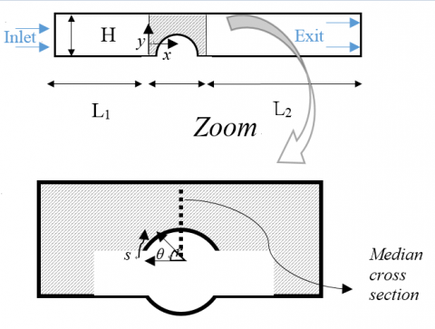
The physical model is a heat exchanger with aluminum foam in forced convection characterized by a steady laminar flow. The 2D sketch of the compact heat exchanger under investigation is showed in Figure 1. An arrangement of five tubes confined into metal foam represents the tubular heat exchanger. The distance 2H, is equal to 16.8 mm and the diameter d of the tubes is 11.2 mm. The heat exchange system is characterized by the height Htot of 84 mm and the length Lmf of 58 mm.
Figure 1. Physical domain
The local volume averaging method is employed, as indicated in [21], in order to reproduce the thermal and fluid dynamic behavior inside the system. Whitaker established the governing equations from the Navier-Stokes and energy equation [22].
An appropriate volume, called Representative Elementary Volume (REV), was used in order to write the average of the local variables. The metal foam, in particular the aluminum foam, is assumed homogeneous and isotropic and the thermal and physical properties of the fluid and solid phases are considered constant. The Darcy–Forchheimer-Brinkman condition and LTNE hypothesis are assumed to model the behavior of the metal foam. The viscous dissipation and buoyancy force are overlooked; moreover, the thermal contact resistances between the tube surface and foam is neglected. The governing equations, using the hypotheses indicated, are:
-Continuity equation
$\frac{\partial u}{\partial x}+\frac{\partial v}{\partial y}=0$ (1)
-x- momentum equation
$\begin{align} & {{\rho }_{f}}\left( \frac{u}{{{\varepsilon }^{2}}}\frac{\partial u}{\partial x}+\frac{v}{{{\varepsilon }^{2}}}\frac{\partial u}{\partial y} \right)=-\frac{\partial p}{\partial x}+\frac{{{\mu }_{f}}}{\varepsilon }\left( \frac{{{\partial }^{2}}u}{\partial {{x}^{2}}}+\frac{{{\partial }^{2}}u}{\partial {{y}^{2}}} \right)+ \\ & -\frac{{{\mu }_{f}}}{K}u-\frac{{{C}_{F}}}{{{K}^{1/2}}}{{\rho }_{f}}\sqrt{{{u}^{2}}+{{v}^{2}}}u \\ \end{align}$ (2)
-y-momentum equation
$\begin{align} & {{\rho }_{f}}\left( \frac{u}{{{\varepsilon }^{2}}}\frac{\partial v}{\partial x}+\frac{v}{{{\varepsilon }^{2}}}\frac{\partial v}{\partial y} \right)=-\frac{\partial p}{\partial y}+\frac{{{\mu }_{f}}}{\varepsilon }\left( \frac{{{\partial }^{2}}v}{\partial {{x}^{2}}}+\frac{{{\partial }^{2}}v}{\partial {{y}^{2}}} \right)+ \\ & -\frac{{{\mu }_{f}}}{K}v-\frac{{{C}_{F}}}{{{K}^{1/2}}}{{\rho }_{f}}\sqrt{{{u}^{2}}+{{v}^{2}}}v \\ \end{align}$ (3)
in which ɛ is the porosity, ρf and μf are fluid density and viscosity, u and v are the velocity components in Cartesian coordinates, K and CF are the metal foam permeability and inertial coefficient, respectively.
-Fluid phase energy equation
$\begin{align} & {{\left( \rho {{c}_{p}} \right)}_{f}}\left( u\frac{\partial {{T}_{f}}}{\partial x}+v\frac{\partial {{T}_{f}}}{\partial y} \right)=\varepsilon {{k}_{f}}\left( \frac{{{\partial }^{2}}{{T}_{f}}}{\partial {{x}^{2}}}+\frac{{{\partial }^{2}}{{T}_{f}}}{\partial {{y}^{2}}} \right)+ \\ & +{{h}_{sf}}{{\alpha }_{sf}}\left( {{T}_{s}}-{{T}_{f}} \right) \\ \end{align}$ (4)
-Solid phase energy equation
$\left( 1-\varepsilon \right){{k}_{s}}\left( \frac{{{\partial }^{2}}{{T}_{f}}}{\partial {{x}^{2}}}+\frac{{{\partial }^{2}}{{T}_{f}}}{\partial {{y}^{2}}} \right)-{{h}_{sf}}{{\alpha }_{sf}}\left( {{T}_{s}}-{{T}_{f}} \right)=0$ (5)
where cp is the fluid specific heat, kf and ks are the fluid and solid phase thermal conductivity, Tf and Ts are the temperature of fluid phase and solid matrix of metal foam, respectively. The terms αsf and hsf are the specific surface area density and the interfacial heat transfer coefficient between the fluid phase and solid matrix, due to the assumption of the LTNE model, respectively.
The correlations of Calmidi are used to evaluate K and CF [23]:
$K=0.00073{{\left( 1-\varepsilon \right)}^{0.0224}}{{\left( \frac{{{d}_{f}}}{{{d}_{p}}} \right)}^{-1.11}}{{d}_{p}}^{2}$ (6)
And
${{C}_{F}}=0.00212{{\left( 1-\varepsilon \right)}^{-0.132}}{{\left( \frac{{{d}_{f}}}{{{d}_{p}}} \right)}^{-1.63}}$ (7)
where df and dp are respectively the fiber and pore diameter of the aluminum foam. The geometrical parameters of the metal foam are in relation with the porosity value, as can be seen in the following correlation [24]:
$\frac{{{d}_{f}}}{{{d}_{p}}}=1.18\sqrt{\frac{1-\varepsilon }{3\pi }}\left( \frac{1}{1-{{e}^{-\left( 1-\varepsilon \right)/0.04}}} \right)$ (8)
The following relationships are employed to evaluate asf and hsf [25]:
${{\alpha }_{sf}}=\frac{3\pi {{d}_{f}}}{{{\left( 0.59{{d}_{p}} \right)}^{2}}}(1-{{e}^{-(1-\varepsilon )/0.04}})~$ (9)
And
$h_{sf}=$$\{ \begin{cases} (0.75Re_{df}^{0.4}Pr^{0.37}_{air})(\frac{k_f}{d_f}) & 1≤Re_{df}≤40\\ (0.51Re_{df}^{0.5}Pr^{0.37}_{air})(\frac{k_f}{d_f}) & 40≤Re_{df}≤10^3\\ (0.26Re_{df}^{0.6}Pr^{0.37}_{air})(\frac{k_f}{d_f}) & 10^3≤Re_{df}≤2\times10^5 \end{cases} $ (10)
where Redf is the Reynolds number referred to ligament diameter:
\([R{{e}_{{{d}_{f}}}}=\frac{{{\rho }_{f}}{{u}_{0}}{{d}_{f}}}{{{\mu }_{f}}}\) (11)
and Prair is the Prandtl number of the working fluid, air, that is evaluated as:
$P{{r}_{air}}=\frac{{{\mu }_{f}}{{c}_{p}}}{{{k}_{f}}}$ (12)
The key parameters of the metal foam, employed in this study, are listed in Table 1.
Table 1. Parameters of the used aluminum foam
|
PPI |
ɛ |
K(m2) |
CF |
|
20 |
0.935 |
1.172 e-7 |
0.1 |
The finite volume method is applied in order to obtain the solutions of the governing equations. Fluent 15.0 is used to carry out the numerical investigations. The SIMPLE algorithm
is accomplished for the pressure-velocity coupling; the least
square cell is used to evaluate the gradient evaluation for the spatial discretization. The pressure calculation is done by means of the PRESTO algorithm; the second order upwind scheme is used for energy and momentum equations. Convergence criteria are considered equal to 10-5 for the continuity and the velocity components while for the energy equal to 10-8.
As the computational domain is utilized half of a single tube, as represented in Figure 2.
Figure 2. Computational domain
The half tube is totally or partially enclosed in the aluminum foam. The height of system is equal to H, the length Lmfis the same of the physical domain. In this scheme, the heat exchanger is arranged in a parallel plates channel with L1and L2equal to 0.20 m and 0.80 m, respectively.
The thicknesses of metal foam have been indicated as t, as can be seen in the Figure 3. Their values have been obtained as ratio respect to the distance center-to-center of two consecutive tubes (I); in fact, in order to obtain the metal foam thicknesses, several ratios t/I have been considered, equal to: ¼, ½, ¾, 1.
Figure 3. Geometrical metal foam configuration
The grid is made up of rectangular cells into the entire computational domain Three different types of grids were analyzed to find an independent solution from the mesh. They are constituted by 28500 cells, 114000 cells and 456000 cells for the configuration characterized by t/I equal to ¾. In corresponding of an inlet air velocity equal 0.511 m/s (Red = 392), the evaluation of the thermal power $\dot{Q}$, as showed in Table 2, highlights that the grid with 114000 cells had 0.3 % error than the mesh with 456000 cells. The grid adopted for the simulations was the one with 114000 elements because it was represented a compromise between solution accuracy and convergence. The grids for the other configurations have been made up of with the same criteria of the construction of the mesh for the ratio t/I equal to ¾.
Table 2. Grid independence and numerical results
|
Cells Number |
$\dot{Q}$ (W) |
% error |
|
28500 |
215.65 |
1.2% |
|
114000 |
213.75 |
0.3% |
|
456000 |
213.09 |
------ |
$R{{e}_{d}}=\frac{{{\rho }_{f}}{{u}_{0}}d}{{{\mu }_{f}}}$ (13)
Ranges from 56 to 1120. The inlet air velocities u0 are estimated from the definition of Red and the following values are obtained, as shown in Table. 3.
Table 3. Inlet air velocity values
|
Red |
uo (m/s) |
|
56 |
0.073 |
|
168 |
0.219 |
|
280 |
0.365 |
|
392 |
0.511 |
|
560 |
0.730 |
|
843 |
1.10 |
|
1120 |
1.46 |
The boundary conditions employed for the investigations are the following: the upper and bottom edges of the domain are considered symmetric, the tube wall is an isothermal edge with the temperature equal to 323.16 K and indicated as Tw, the inlet air temperature, indicated as T0, is equal to 288.16 K and to the exit is imposed the overflow condition. The reference length is the diameter of the tube d for the dimensionless number.
The thermal and fluid dynamic investigations are carried out for a fixed temperature on the external surface of tube equal to 323.16 K and for different inlet air velocity values. The fluid flow is laminar and the LTNE hypothesis is assumed to evaluate the energy equations. For the dimensionless number, the reference length is the diameter of the tube d, equal to 112 mm. The average total heat transfer coefficient $\bar{h_{tot}}$
evaluated as:\({{\bar{h}}_{tot}}={{\bar{h}}_{f}}+{{\bar{h}}_{s}}\) (14)
where $\bar{h_{f}}$ and
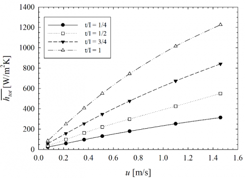
$\bar{h_{s}}$ are the fluid and solid phase heat transfer coefficients, respectively. The average heat transfer coefficient are calculated as $\bar{h_{tot}}=\frac{\dot{Q}_{tot}}{A(T_w-W_o)}$, $\bar{h_{f}}=\frac{\dot{Q}_f}{A(T_w-W_o)}$, $\bar{h_{s}}=\frac{\dot{Q}_s}{A(T_w-W_o)}$ with: $\dot{Q}_{tot}=\dot{Q}_f+\dot{Q}_s$ where $\dot{Q}_{tot}$ (the total heat transfer rate) is equal to sum of the thermal power referred to the fluid phase ($\dot{Q}_f$) and the solid matrix ($\dot{Q}_s$).The heat transfer coefficient results, evaluated on the external tube surface are plotted in the Figure 4 for different values of ratio t/I.
Figure 4. Average heat transfer coefficient as a function of x-velocity for different t/I
This coefficient increases with increasing metal foam thickness because the presence of the foam improves the heat transfer. This enhancement is more visible for higher values of air velocity.
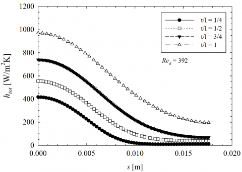
The local heat transfer coefficient, evaluated on the surface of the heated tube, is also reported, in the Figure 5, only for Red equal to 392 because the behavior is the same for all Reynolds numbers.
Figure 5. Local htot as a function of the curvilinear abscissa s for different metal foam thicknesses
Also the local htot values increase with increasing of thickness t for all Reynolds numbers.
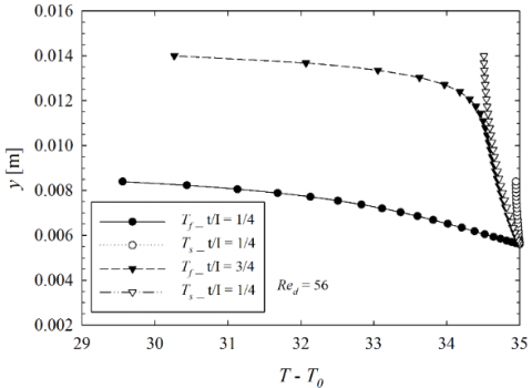
In the Figure 6.a and 6.b, the temperature profiles along the median cross section into metal foam are presented for Red equal to 56 and 1120. It can be observed two different temperature profiles, one referred to the fluid phase and another linked to the solid matrix of the metal foam, for the LTNE model assumption.
(a)
(b)
Figure 6. Temperature profile along the median section for t/I equal to ¼ and ¾
For clarity, the temperature profiles are showed only for t/I equal to ¼ and ¾. One can see the difference between the fluid and solid temperature increases with increasing Redfor both metal foam thickness values. Moreover, in corresponding of Red=56, the discrepancy T –T0 between the two phases is higher for t/I = ¼ respect to t/I equal to ¾; on the other hand, for Red=1120, the difference between the two metal foam phases is almost the same. In addition, one can observe that in corresponding of t/I = ¾, ΔT is higher than the case with a ratio t/I minor because, in the first case, it is obtained a major heat exchange, as seen also with the evaluation of htot.
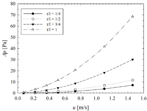
Below, in the Figure 7, the pressure drop Δp between the inlet and outlet sections is reported for the various metal foam thicknesses. As can be observed, the major quantity of metal foam causes an increase of pressure drop because there is an increment of the friction during the fluid motion.
To evaluate the efficacy of the metal foam application and the best metal foam thickness in the heat exchanger, a comparison is executed respect to the case in which the tube is totally enclosed in the metal foam. The Energy Performance Ratio (EPR) is evaluated to appreciate the convenient thickness of the metal foam considering both the improvement of heat transfer and the increase of pressure drop.
The EPR is calculated as below:
$EPR=\frac{{{\left( j/f \right)}_{pf}}}{{{\left( j/f \right)}_{tf}}}$ (15)
Figure 7. Δp as a function of u for several t/I
where the subscripts pf and tf indicates the case partially or totally filled with the metal foam, respectively. In the EPR expression, the friction factor f and the Colburn factor j are evaluated as in the work of Odabaee and Hooman [26]:
$j=\frac{h_{tot}}A{\dot{m}c_p}Pr_{air}^{2/3}$ (16)
and
$f=\frac{2\Delta p}{{{\rho }_{f}}{{u}_{0}}^{2}}$ (17)
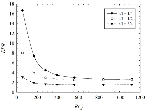
In the Figure 8, the EPR is reported as a function of Red.
Figure 8. EPR for various t/I values
As shown in the Figure 8, the EPR increases with decreasing of ratio t/I, highlighting the advantage of using a metal foam with a lower value of thickness, especially for lower Reynolds numbers.
A numerical analysis on a heat exchanger with aluminum foam characterized by a porosity equal to 0.935 and a PPI number of 20 has been carried out to estimate the thermal and fluid dynamic behavior of the heat exchange system. The results in terms of heat transfer coefficient show that higher thicknesses improve the heat transfer respect to a case with a minor quantity of the aluminum foam. Furthermore, the temperature profiles along the median section into the metal foam for fluid and solid phases are showed demonstrating that the temperature difference between two phases is higher for t/I minor when Red assumes lower values. Another result shows that the pressure drop of the heat exchanger increases with increasing of t. As a final observation, the EPR has been calculated to show how the efficiency worsens with increasing of porous thickness because the pressure drop increases more than the heat exchange.
[1] Mahjoob S, Vafai K. (2008). A synthesis of fluid and thermal transport models for metal foam heat exchangers. Int. J. Heat Mass Transf 51(15–16): 3701-3711. https://doi.org/10.1016/j.ijheatmasstransfer.2007.12.012
[2] Tan WC, Saw LH, Thiam HS, Xuan J, Cai Z, Yew MC. (2018). Overview of porous media/metal foam application in fuel cells and solar power systems. Renew. Sustain. Energy Rev 96: 181-197. https://doi.org/10.1016/j.rser.2018.07.032
[3] Al-Athel KS. (2017). Computational assessment of the heat transfer coefficient under forced convection of multiple metal foam fins heat sinks. Arab. J. Sci. Eng 42(11): 4853-4861. https://doi.org/10.1007/s13369-017-2656-2
[4] Bai WR, Yuan XH, Liu X. (2017). Numerical investigation on the performances of automotive thermoelectric generator employing metal foam. Appl. Therm. Eng 124: 178-184. https://doi.org/10.1016/j.applthermaleng.2017.05.146
[5] Kim DY, Sung TH, Kim KC. (2016). Application of metal foam heat exchangers for a high-performance liquefied natural gas regasification system. Energy 105: 57–69. https://doi.org/10.1016/j.energy.2015.10.056
[6] Buonomo B, Ercole D, Manca O, Nardini S. (2017). Numerical investigation on thermal behaviors of two-dimensional latent thermal energy storage with PCM and aluminum foam. Journal of Physics: Conference Series 796(1): 012031 https://doi:10.1088/1742-6596/796/1/012031
[7] Huisseune H, Schampheleire SD, Ameel B, Paepe MD. (2015). Evaluation of the thermal hydraulic performance of round tube metal foam heat exchangers for HVAC applications. Presented at Proceedings of the 15th Int. Heat Transfer Conf., IHTC-15, Kyoto, Japan, IHTC15-8831.
[8] Kim SY, Paek JW, Kang BH. (2000). Flow and heat transfer correlations for porous fin in a plate-fin heat exchanger. ASME J. Heat Transfer 122: 572-578. https://doi:10.1115/1.1287170
[9] Cicala G, Cirillo L, Diana A, Manca O, Nardini S. (2016). Experimental evaluation of fluid dynamic and thermal behaviors in compact heat exchanger with aluminum foam. Energy Procedia 101: 1103-1110. https://doi.org/10.1016/j.egypro.2016.11.150
[10] Chumpia A, Hooman K. (2019). Performance of tubular aluminum foam heat exchangers in multiple row bundles. J. Therm. Anal. Calorim 135(3): 1813-1822. https://doi.org/10.1007/s10973-018-7348-y
[11] Xu HJ, Gong L, Zhao CY, Yang YH, Xu ZG. (2015). Analytical considerations of local thermal non-equilibrium conditions for thermal transport in metal foams. Int. J. Therm. Sci 95: 73-87. https://doi.org/10.1016/j.ijthermalsci.2015.04.007
[12] Lu W, Zhang T, Yang M, Wu Y. (2017). Analytical solutions of forced convective heat transfer in plate heat exchangers partially filled with metal foams. Int. J. Heat Mass Transf 110: 476-481. https://doi.org/10.1016/j.ijheatmasstransfer.2017.02.087
[13] Odabaee M, Hooman K, Gurgenci H. (2011). Metal foam heat exchangers for heat transfer augmentation from a cylinder in cross-flow. Trans. Porous Media 86: 911-923. https://doi.org/10.1007/s11242-010-9664-y
[14] Lin W, Sunden B, Yuan J. (2013). A performance analysis of porous graphite foam heat exchangers in vehicles. Appl. Therm. Eng 50: 1201-1210. https://doi.org/10.1016/j.applthermaleng.2012.08.047
[15] Zafari M, Panjepour M, Emami MD, Meratian M. (2015). Microtomography-based numerical simulation of fluid flow and heat transfer in open cell metal foams. Appl. Therm. Eng 80: 347–354. https://doi.org/10.1016/j.applthermaleng.2015.01.045
[16] Alhusseny A, Turan A, Nasser A. (2017). Rotating metal foam structures for performance enhancement of double-pipe heat exchangers. Int. J. Heat Mass Transf 105: 124-139. https://doi.org/10.1016/j.ijheatmasstransfer.2016.09.055
[17] Moon C, Kim HD, Kim KC. (2018). Kelvin-cell-based metal foam heat exchanger with elliptical struts for low energy consumption. Appl. Therm. Eng 144: 540-550. https://doi.org/10.1016/j.applthermaleng.2018.07.110
[18] Alvandifar N, Saffar-Avval M, Amani E. (2018). Partially metal foam wrapped tube bundle as a novel generation of air-cooled heat exchangers. Int. J. Heat Mass Transf 118: 171-181. https://doi.org/10.1016/j.ijheatmasstransfer.2017.10.104
[19] Chiappini D, Festuccia A, Bella G. (2018). Coupled lattice Boltzmann finite volume method for conjugate heat transfer in porous media. Numer. Heat Transf. Part A Appl 73(5): 291–306. https://doi.org/10.1080/10407782.2018.1444868
[20] Buonomo B, Pasqua AD, Ercole D, Manca O, Nardini S. (2018). Numerical investigation on aluminum foam application in a tubular heat exchanger. Heat Mass Transf 54: 2589-2597. https://doi.org/10.1007/s00231-018-2305-7
[21] Nield DA, Bejan A. (2013). Convection in porous media. 4th ed springer, New York.
[22] Whitaker S. (1998). The method of volume averaging, springer, Netherlands.
[23] Calmidi VV. (1998). Transport phenomena in high porosity metal foams. Ph.D. thesis University of Colorado, Boulder, CO.
[24] Bhattacharya A, Calmidi VV, Mahajan RL. (2001). Thermophysical properties of high porosity metal foams. Int. J. Heat Mass Transfer 45: 1017-1031. https://doi.org/10.1016/s0017-9310(01) 00220-4
[25] Calmidi VV, Mahajan RL. (2000). Forced convection in high porosity metal foams. ASME J. Heat Transfer 122: 557-565. https://doi.org/10.1115/1.1287793
[26] Odabaee M, Hooman K. (2012). Metal foam heat exchangers for heat transfer augmentation from a tube bank. Appl. Therm. Eng 36: 456-463. https://doi.org/10.1016/j.applthermaleng. 2011.10.063