Ya Wei
OPEN ACCESS
This paper designs a fire detection system based on four-rotor aircraft, aiming to accurate measure the temperature and smoke in the open area at the occurrence of fires and their secondary disasters. The detection platform was established through the analysis on flight dynamic model. The proportional–integral–derivative (PID) control was introduced to control the four rotors in all directions, so that the aircraft can fly stably in open area. A temperature sensor and a smoke sensor were installed to allow the rotors capture temperature and smoke concentration in smooth flight. Through wireless control, the values of the detected temperature and smoke and the scene picture are sent back to the control center in real time. Once the data surpasses the critical values, the system will send out an alarm. The research findings shed new light on fire detection and pre-warning of secondary disasters.
fire detection, four-rotor aircraft, secondary disaster, proportional-integral-derivative (PID) control
Frequent fire accidents are a byproduct of the improving standard of living. The various types of fires (e.g. forest fire and high-rise fire) and their secondary disasters pose a severe challenge to firefighters, making the rescue mission much more complex. To adapt to the new situation, the traditional fire monitoring methods, which rely on patrollers, fixed cameras, aircrafts or satellites, must be improved substantially.
One of the improved methods is the multi-objective coordinated unmanned aerial vehicle (UAV) system. This approach can achieve all-round coverage of the target area, monitor the situation of fireground and pinpoint the source of ignition. However, the system cannot provide rescuers with the relevant data on the environment.
To overcome the limitations of the traditional fire monitoring methods, this paper designs a fire detection system based on four-rotor aircraft, aiming to accurate measure the temperature and smoke in the open area at the occurrence of fires and their secondary disasters [1]. With the system, the temperature and smoke are detected via aerial monitoring, the detected data are sent back to the control center in real time, and the emergency response is made timely based on the data.
In general, the aircraft control targets the following movements: longitudinal motion, hovering motion, pitching motion, yaw motion, flip motion, front and rear motions, as well as left and right motions. To design a proper fire detection system, the first step is to set up a proportional–integral–derivative (PID) controller and construct a dynamic model of the aircraft [2]. In this paper, the system is developed under the following assumptions.
(1) For simplicity, the four-rotor aircraft is considered symmetric, and its center of gravity coincides with the geometric center and the origin of its coordinate system;
(2) The ground effect is negligible when the aircraft flies at a low altitude;
(3) The air resistance only depends on the flying speed;
(4) The lift and reaction torque are both proportional to the square of the rotation speed of the propeller.
According to the requirements of PID control algorithm, the parameter values of the dynamic model were determined by trial and error on Matlab. Then, the PID controller and the dynamic model were combined into the fire detection system based on four-rotor aircraft. Finally, the dynamic response, steady-state error and overshoot of the proposed system were verified through simulation.
3.1 Four-rotor aircraft
The dynamic model was constructed by Newton–Euler equations. First, the inertial matrix of the aircraft was set up under the inertial coordinate system E (OXYZ) and the body coordinate system B (OXYZ). After that, the attitude angle matrix of the Newton-Euler equations was written out, followed by the transformation matrix of B (OXYZ) to E (OXYZ). Based on Newton–Euler equations, the transformation matrix, and the formula of the resultant of lift, gravity and air resistance, the linear motion equations of the four-rotor aircraft in the ground coordinate system can be expressed as:
$\mathrm{mx}=\sum_{1}^{4}(-1)^{i} k w_{i}^{2}(\sin \gamma \sin \varphi+\cos \gamma \cos \varphi \sin \theta)-k_{d x} \dot{x}$ (1)
$\mathrm{my}=\sum_{1}^{4}(-1)^{i} k w_{i}^{2}(\cos \gamma \sin \theta \sin \varphi-\cos \varphi \sin \gamma)-k_{d y} \dot{y}$ (2)
$\mathrm{mz}=\sum_{1}^{4}(-1)^{i} k w_{i}^{2} \cos \theta \cos \gamma-m g-k_{d z} \dot{z}$ (3)
The torques of the four-rotor aircraft during the flight can be described as:
$M^{b}=\left[M_{x} \quad M_{y} \quad M_{z}\right]^{T}=\left[\begin{array}{c}{L\left(K W_{4}^{2}-K W_{2}^{2}\right)} \\ {L\left(K W_{3}^{2}-K W_{1}^{2}\right)} \\ {\sum_{1}^{4}(-1)^{i} k_{d} W_{i}^{2}}\end{array}\right]$ (4)
where
is the coefficient of air resistance. Then, the aircraft torque can be obtained as:$M^{b}=I \Omega^{b}+\Omega^{b} \times\left(I \Omega^{b}\right)=\left[\begin{array}{c}{I_{x} \gamma} \\ {I_{y} \theta} \\ {I_{z} \varphi}\end{array}\right]+\left[\begin{array}{c}{\theta \varphi\left(I_{z}-I_{y}\right)} \\ {\gamma \varphi\left(I_{z}-I_{x}\right)} \\ {\theta \gamma\left(I_{y}-I_{x}\right)}\end{array}\right]=\left[\begin{array}{l}{I_{x} \gamma+\theta \varphi\left(I_{z}-I_{y}\right)} \\ {I_{y} \theta+\gamma \varphi\left(I_{z}-I_{x}\right)} \\ {I_{z} \varphi+\varphi \gamma\left(I_{y}-I_{x}\right)}\end{array}\right]$ (5)
From equations (4) and (5), the angular motion equations of the aircraft can be obtained as:
$I_{x} \gamma=\left(K W_{4}^{2}-K W_{2}^{2}\right) l-\left(I_{z}-I_{y}\right) \theta \varphi$ (6)
$I_{y} \theta=\left(K W_{3}^{2}-K W_{1}^{2}\right) l-\left(I_{z}-I_{x}\right) \gamma \varphi$ (7)
$I_{z} \varphi=\sum_{1}^{4}(-1)^{i} k_{d} W_{i}^{2}-\theta \gamma\left(I_{y}-I_{x}\right)$ (8)
where K is a constant related to the air density and the effective area vertical to the moving direction of the aircraft. Equations (1)~(3) and (6)~(8) constitute the dynamic model of the four-rotor aircraft in our fire detection system. Considering that the stability of the angle under no wind or slow speed, the equilibrium point position of the dynamic model can be simplified as:
$\mathrm{m} \ddot{x}=\sum_{1}^{4}(-1)^{i} k w_{i}(\sin \gamma \sin \varphi+\cos \gamma \cos \varphi \sin \theta)$ (9)
$\mathrm{m} \ddot{\mathrm{y}}=\sum_{1}^{4}(-1)^{i} k w_{i}(\cos \gamma \sin \theta \sin \varphi-\cos \varphi \sin \gamma)$ (10)
$\mathrm{m} \ddot{\mathrm{z}}=\sum_{1}^{4}(-1)^{i} k w_{i} \cos \theta \cos \gamma-m g$ (11)
$I_{x} \gamma=\left(K W_{4}^{2}-K W_{2}^{2}\right) l$ (12)
$I_{y} \theta=\left(K W_{3}^{2}-K W_{1}^{2}\right) l$ (13)
$I_{z} \varphi=\sum_{1}^{4}(-1)^{i} k_{d} W_{i}^{2}$ (14)
3.2 PID control
Based on the PID model design, the transfer function of the PID control can be expressed as:
$\mathrm{G}(\mathrm{s})=\frac{M(S)}{E(S)}=K_{p}\left[1+\frac{1}{T_{i}}+T_{d} S\right]$ (15)
In a stable flight, the constant load of the motor can be described as:
$T_{m}+\frac{d w}{d t}+w=C_{d} u_{a}$ (16)
The aircraft data and PID simulation parameters (Table 1) were acquired through repeated flight tests.
Table 1. The aircraft data and PID simulation parameters
|
Parameter |
Numerical value |
|
m/kg |
1.4 |
|
l/mg |
0.185 |
|
k/(N·s-2) |
3Î10-5 |
|
d/(N·s-2) |
7.5Î10-7 |
|
Ix/(kg·m2) |
2.4Î10-3 |
|
Iy/(kg·m2) |
2.4Î10-3 |
|
Iz/(kg·m2) |
5.3Î10-3 |
|
N |
Kp |
Ti |
Td |
|
1 |
16 |
0.01 |
1 |
|
2 |
4 |
0.01 |
0.01 |
|
3 |
10 |
0.01 |
1 |
|
4 |
10 |
0.1 |
0.01 |
|
5 |
6 |
0.1 |
1 |
|
6 |
10 |
0.01 |
0.01 |
The four-rotor aircraft-based system [3] requires two main functions: smooth flight control and fire monitoring. The hardware of the system was designed according to the two functions.
4.1 Microprocessor
The monitoring function of the system hinges on an ATMEGA2560 (ATMEL) microprocessor. With a clock frequency of 16MHz, the microprocessor features a 4K-bit serial presence detect (SPD) EEPROM, eight-channel PWM input and output, and JTAG, SPI and USART interfaces. This device can correctly compute and output the control signals through the flight, and coordinate the various sensors connected to it.
4.2 Sensors
Sensors [4], as the sensory organs of the aircraft, directly affects the accuracy of monitoring. The sensors of our fire monitoring system must be power efficient, highly reliable, small and lightweight, in addition to meeting the test requirements. In view of these, the HMC5883 compass [5] was selected to orient the aircraft; the acceleration and attitude angle were measured by six-axis MEMS sensor MPU6000 [6], which integrates a three-axis gyroscope and a three-axis accelerator; the attitude angle and acceleration were collected continuously to achieve real-time smooth control of the flight [7]. In addition, the temperature and smoke in fire and secondary disaster were detected by a digital temperature sensor DS18B20, which has a single bus interface, and a smoke sensor MQ-2, which can detect liquefied petroleum gas, methane, propane, butane and smoke.
Once detected, the smoke signal is firstly converted into the analog signal in the MQ-2 detection circuit [8], then into the digital signal via ADS0832, and finally sent to the single-chip microprocessor. If there is no fire, the temperature and smoke concentration being detected are both above the critical values. However, when both the buzzer alarms and the PAO port lights up, there must be an occurrence of fire and secondary disaster.
4.3 Module design
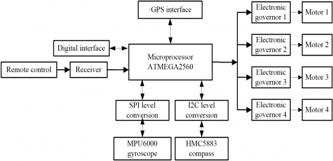
According to the above function, the hardware system includes the controller module, the sensor module, the motor control module and the wireless communication module. The architecture of the hardware system is presented in Figure 1 below.
Figure 1. The architecture of the hardware system
In the controller module, the signal collected by each electronic governor is processed by the microprocessor, and then used to control the motor speed via the I2C bus. In the sensor module, the temperature and smoke signals are collected by the sensors. In the motor control module, the electronic governors control the motor power to life the aircraft, and control the motor speed to achieve the changes between flipping, pitching and yaw motions [8]. The wireless communication module ensures the communication between the control station and the aircraft. The ground station receives the data from the aircraft and sends the control signal to the latter.
5.1 Processing program
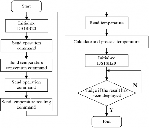
The temperature is detected by the DS18B20 sensor chip [9], which is known for its good stability. The chip integrates the functions of temperature detection and data transmission. Thus, the processing program can be implemented according to the work cycle embedded in the chip [10]. The ambient temperature will be displayed on an LCD 1602 screen [11].
The steps of MCU reading temperature include: (1) skip the ROM operation; (2) send the temperature conversion command; (3) skip the ROM operation; (4) send the command of reading temperature value; (5) read the temperature value, operation flow chart [4] is shown in Figure 2. Note that the temperature after the DS18B20 conversion is stored in binary form within the high-speed memory.
Figure 2. DS18B20 program
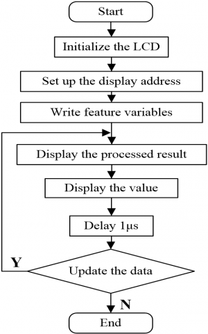
5.2 Display program
The temperature is displayed in the LCD 1602 screen. The input data of the screen must be written in the form of ASCII. After initialization, the data can be imported in random order, and the energy end should be set to a low level, laying the basis for the next operation. The display process is explained in details in Figure 3.
Figure 3. Display program
5.3 Transmission program
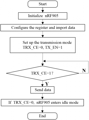
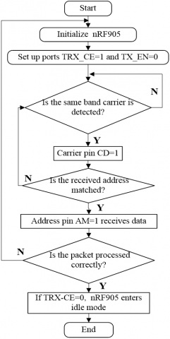
The work mode of nRF905 receiver is presented in Table 3. It can be seen that the SPI port program starts with the register configuration [12]. Then, the data and address are sent to the receiver at the proper time. After that, TRX_CE and TX_EN ports are defined and the Shock Burst TM transmission mode is activated. Next, the nRF905 will continue sending data until reaching a TRX_CE. Finally, the receiver will automatically enter the idle mode [13]. This process is illustrated in Figure 4.
Figure 4. Transmission program 1
Figure 5. Transmission program 2
After the date is initialized in nRF905 receiver, the MCU will configure the TRX_CE and TX_EN ports, turning the receiver into the receiving mode. The receiver will detect data continuously for 650μs and wait for data reception. If a carrier in the same frequency is detected, the carrier pin CD will be set to a high level and start receiving data. The CRC check will be performed until the end of data reception. If an error is detected, the module will return to the data receiving mode; otherwise, TRX_CE will be changed to a low level, and the receiver will automatically enter the idle mode. This process is depicted in Figure 5 above.
After all modules had been connected, the hardware of each module was debugged to ensure normal operation.
6.1 Wireless communication debugging
The wireless communication debugging has three targets, namely, the remote control, the wireless transmission and the compass.
On the remote-control debugging, the 2.4G remote controller has the address code and an automatic frequency conversion mode. First, the remote-control receiver was paired with the transmitter. The pairing is successful if the red light on the receiver stops flickering. Then, the remote controller was calibrated with the flight control chip. The calibration aims to set up the connection between the aircraft and the controller, as well as setting the range of each remote channel and the flight mode. The calibration shows that the travel volumes of the throttle, overturning, yaw and flight transfer channels were respectively 760, 665, 659, 780 and 1,023, respectively, showing that the system is stable.
On wireless transmission debugging, an image was displayed on the screen after the following parts were properly connected and powered: flight control chip, OSD, camera, transmitter and receiver. Then, the transmitter and receiver were set to the same channel.
On compass debugging, the offset of the compass, X: -97, Y:5, Z:0, was obtained by connecting the compass to the flight control chip and the control station, after several rotations. Then, the front of the compass was set to the local north.
6.2 Comprehensive debugging
After all function modules had been correctly connected, the detection system was powered on, the remote controller was initialized, and the wireless transmission receiver was turned on. Soon, the red and blue lights on the flight control board flickered alternatively. When the blue light became stable and the red light flashed, it means the GPS had connected to the satellites and the number of satellites was displayed in the control station or the screen. If there is no image or parameter on the screen, efforts should be made to ensure the receiver and transmitter are in the same channel, and check if the input/output video signals are connected correctly to the signal integration module OSD.
The aircraft was debugged once more. With the hand controller in manual mode, the electronic governor was unlocked by pushing the throttle down the right side for about 3s, and releasing it when the lights on the flight control board stopped flashing (an indicator of successful unlocking and the readiness of the aircraft). If unlocking fails, efforts should be made to check if the throttle stroke of the remote controller is too small or the compass is not accurate enough.
If so, the throttle needs to be reset and the compass requires readjustment. After that, the throttle was pushed, turning on the motor, and controlled so that the aircraft was about to leave the ground. Next, the remote direction stick on the left was turned to check if the remote direction channel is normal. If the arm feels a force from the right, the stick should be pushed forward to see if a force will come from the back. If so, the aircraft operates in a normal procedure and can be used for trial flight. Otherwise, the system should be modified and further debugged.
This paper designs a fire detection system based on four-rotor aircraft. The system design covers both software and hardware, and the parameters of each channel were determined by PID control model and trial and error. The proposed system was debugged module by module simulation. Then, the crucial values of temperature in fire and smoke concentration in secondary disaster were determined through simulation. Compared with the actual data, the system was proved as capable of monitoring the fire scene in real time, and warning the occurrence of secondary disasters.
This paper is supported by Shaanxi Science and Technology Department project (2018GY-145), App Application and Big Data of Intelligent Government Service, General Project (Industrial Field).
[1] Valavanis, K.P. (2013). Special issue on current developments and state of the Artin unmanned aircraft systems. Intelligent & Robotic Systems, 1(3): 46-52. https://doi.org/10.1007/s10846-012-9787-1
[2] Ye, S.Q., Zhan, L. (2015). Quad-rotor aircraft attitude control system based on PID control. Computer and Modernization, (5): 117-120. https://doi.org/10.3969/j.issn.1006-2475.2015.05.025
[3] Niu, H.F., Wu, H.Y., Chen, Y. (2015) Sliding mode control of four rotor aerocraft based on backstepping. High Technology Communication, 25(12): 1083-1091. https://doi.org/10.3772/j.issn.1002-0470.2015.12.013
[4] Nie, B.W., Ma, H.X., Wang, J., Wang, J.W. (2014). Study on actualities and critical technologies of micro/mini quadrotor. Electronics Optics & Control, 14(6): 113-117. https://doi.org/10.3969/j.issn.1671-637X.2007.06.028
[5] Hu, N.B., Li, J., Zhao, J.Y. (2011). Digital electronic compass based on HMC5883. Sensor World, 12(2): 36-38. https://doi.org/10.3969/j.issn.1006-883X.2011.06.008
[6] Zhang, Q., Yuan, Z.H., Liang, D., Ning, Y.K., Zhao, G.R. (2014). Design of low-power wireless body sensor network node based on MPU6000. Computer Measurement & Control, 22(2): 39-47. https://doi.org/10.3969/j.issn.1671-4598.2014.02.071
[7] Gu, L.H., Cui, C., Gao, S.W., Xu, H. (2015). Gait signal acquisition system based on MPU-6050. Journal of Shenyang University of Technology, 37(2): 173-182. https://doi.org/10.7688/j.issn.1000-1646.2015.02.11
[8] Wu, Z.K., Xie, X.L. (2014). Design of voltage monitoring system based on single chip and C#. Automation and Instrumentation, (4): 71-73. https://doi.org/10.3969/j.issn.1001-9227.2014.04.027
[9] Sun, J.Y. (2013). Research on the design of smoke alarm based on single chip microcomputer. Electronic Test, (15): 56-57. https://doi.org/10.3969/j.issn.1000-8519.2013.15.023
[10] Mai, C.Y., Su, L., Zhu, L. (2012). Multi point wireless image transmission system based on ARM11. Micro Computer Information, (6): 110-112.
[11] Zhang, Q.Q., Zhao, Q.N. (2015) Design of fire alarm system based on MQ-2 sensor. Value Engineering, 13(6): 96-98.
[12] Kuang, Y.H., Liu, M.Y., Shi, K.L. (2016). The four rotor VTOL fixed wing aircraft design. Science & Technology Vision, (24): 36-38. https://doi.org/10.3969/j.issn.2095-2457.2016.24.026
[13] Wang, H., Wang, X., Du, S.L. (2011). ARM9-based USB camera image capture compression and wireless transmission. Video Engineering, 35(3): 29-31. https://doi.org/10.3969/j.issn.1002-8692.2011.03.009