Nandure Narayan Rao* | Pavuluri M.V. Rao | Samresh Kumar
© 2021 IIETA. This article is published by IIETA and is licensed under the CC BY 4.0 license (http://creativecommons.org/licenses/by/4.0/).
OPEN ACCESS
Fibre Metal Laminates (FMLs) are laminates consisting of metal layers and fibre reinforced composite layers. These laminates are designed to improve some specific properties of constituent metals and composites layers. Estimation of First Ply Failure (FPF) Loads of these FMLs is a part in the broad characterization of these materials. A numerical method is developed for the estimation of FPF when these laminates are used as simply supported plates subjected to uniformly distributed load. Various failure criterions are used to identify these loads. The proposed method has been validated with the results of exact (Navier) solution available in the literature. FPFs are estimated for different groups of FMLs based on Aluminum, Titanium and Magnesium layers. The results are presented in the form of non-dimensional FPF and deformation values for various aspect ratios.
numerical methods, classical lamination theory, first ply failure, fibre metal laminates
A hybrid composite laminate which consists of metal layers and fibre reinforced composite layers is called as Fibre Metal Laminate (FML). In 1978 Delft University of Technology has introduced first configuration of this group known as ARALL [1, 2]. In these thin high strength Aluminium alloy sheets and uni/bi-directional Aramid fibre laminas are alternately bonded together. The main motive of this approach was to reduce the weight and to improve the damage tolerance characteristics of materials used for aircraft construction. The improvements are also observed in other areas of fatigue, impact, corrosion and damage resistance, Various combinations of metal layers and reinforced composite layers are being studied [3].
Promising application of this group of material has attracted researchers for comprehensive characterization involving experimentation, development of analytical and numerical techniques for the prediction of its behavior under different loading conditions. Interlaminar failure behavior of GLARE laminates under short beam three-point bending load are investigated for different l/h ratios [4]. Works reported in the literature about impact resistance of FMLs was reviewed [5].
Some investigators have proposed numerical and analytical techniques, which can predict the behavior of FMLs like, stress-strain curve, delamination, impact resistance [5, 6]. It was observed from literature survey that, less information is available about FMLs behavior, when it is used as plate subjected to uniformly distributed loads on its surface. However, the analysis about transverse loading on a rectangular plate subjected to different boundary conditions is very essential to understand the behavior of FMLs properly, so that its uses can be extended.
To identify the existing formulations, a brief literature survey is presented here to analyze the composite plates subjected to uniformly distributed loads. It is relevant since the FML is also a composite material and various methods of flexural analysis of composite plates are discussed in the literature [7-9]. For the last two decades research in this area is focused on the Flexure Analysis of simply supported rectangular composite plate. Solutions are arrived by combining with different failure criteria for identification of FPF [9-11]. Out of many such failures criteria, study shows Tsai-Hill failure criteria has been used by many researchers because of its simplicity in implementing in finding FPF loads [9, 12]. Majority of the work is focused on symmetrical cross-ply laminates. A shear deformable finite element (FE) method was used to estimate the FPFs for laminates with different stacking sequences. The developed procedure is compared with the exact solution for various failure criterion [13]. In the similar way a 3D layer wise mixed FE model for thick composite laminated plates has been proposed to predict the FPF. Results from various 3D and 2D failure theories are analyzed [11]. FE models involves considerably more computation compared to Rayleigh-Ritz method. In context of the advantage of this method.
Based on the literature survey the suitable steps in the present analysis have been identified as. a) Developing a numerical technique based on CLT to calculate stresses and deflections. b) Validation of proposed approximate procedures. c) Applying the procedures for FML.
In the present work CLT [14] coupled with Ritz approximation has been used as a basis to develop a numerical technique to calculate stresses and deformations. FPF loads and transverse deflections for different aspect ratios are used to define the behavior of the plate. Various failure theories have been taken to arrive at the FPF loads of the FMLs. The present analysis is also limited to cross-ply laminates in view of widespread applications in research and industry [2, 15-17].
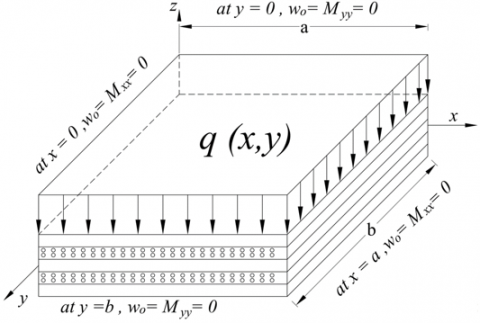
By following the Classical Lamination Theory (CLT) procedure the governing differential equation for a symmetric cross-ply laminate rectangular plate subjected to uniformly distributed load q(x,y),can be expressed as [18].
$D_{11} \frac{\partial^{4} w_{0}}{\partial x^{4}}+2\left(D_{12}+2 D_{66}\right) \frac{\partial^{4} w_{0}}{\partial x^{2} \partial y^{2}}+D_{22} \frac{\partial^{4} w_{0}}{\partial y^{4}}=q(x, y)$ (1)
In the present work Ritz approximation has been considered to develop general form of numerical solution for the above differential equation [19]. The rectangular plate is simply supported at the boundary and as shown in Figure 1. By solving the Eq. (1). The solutions for the approximate central deflections and strains can be obtained as.
$w_{o}(x, y)=\sum_{l=1}^{\infty} \sum_{m=1}^{N} C_{j}^{(l)} \psi_{m}(x) \sin \gamma_{l} y$
$\varepsilon_{x}=\frac{\partial^{2} w_{0}}{\partial x^{2}}=\sum_{l=1}^{\infty} \sum_{m=1}^{N} C_{j}^{(l)} \frac{d^{2} \psi_{m}}{\partial x^{2}} \sin \gamma_{l} y$
$\varepsilon_{y}=\frac{\partial^{2} w_{0}}{\partial y^{2}}=-\sum_{l=1}^{\infty} \sum_{m=1}^{N} C_{j}^{(l)}\left(\gamma_{l}\right)^{2} \psi_{m}(x) \frac{d^{2} \psi_{m}}{\partial x^{2}} \sin \gamma_{l} y$
$\varepsilon_{x y}=\frac{2 \partial^{2} w_{0}}{\partial x \partial y}=-\sum_{l=1}^{\infty} \sum_{m=1}^{N} C_{j}^{(l)} \psi_{m}(x) \frac{d \psi_{0}}{d x} \cos \gamma_{l} y$ (2)
where, $\psi_{m}(x)$ is an approximate function, which satisfy these loading and boundary condition. and $\cos \gamma_{l}=n \times p i / b$.
Figure 1. Loading and boundary conditions of simply supported composite plate
As a composite material, the strength of FML depends on the properties of the materials used, arrangement of the layers in the laminate and on the stress induced due to the loading modes and boundary conditions. With the continuous increase of load on the laminate, the stresses in the individual laminas will also increase. These stresses depend on the arrangement of the laminas in the laminate and may vary in type and magnitude from lamina to lamina. When these stresses in any one of the lamina reaches a value that satisfies a selected failure criterion, that particular lamina can be considered as failed and the load on the laminate at that instant can be considered as First Ply Failure load. Identifying the nature of failure stress and mode of failure (matrix or fiber) are also the features of stress-strain analysis [20]. Different failure criteria are proposed in the literature and in the present work strength-based theories of failure are considered to identify the FPF [11, 13, 20]. These are briefly presented below.
3.1 Maximum stress failure criterion
According to the maximum stress failure criteria, failure of the material is assumed to occur if any one of the conditions satisfied.
fibre tensile mode $\left(\sigma_{1}>0\right), \quad \sigma_{1} \geq S_{1 T}$
fibre compresive mode $\left(\sigma_{1}<0\right), \quad\left|\sigma_{1}\right| \geq\left|S_{1 C}\right|$
Matrix tensile mode $\left(\sigma_{2}>0\right), \quad \sigma_{2} \geq S_{2 T}$
Matrix compressive mode $\left(\sigma_{2}<0\right),$ $\left|\sigma_{2}\right| \geq\left|S_{2 C}\right|$ (3)
3.2 Hashin’s failure criterion
Tensile fibre failure $\left(\sigma_{1}>0\right) ;\left(\frac{\sigma_{1}}{S_{1 T}}\right)^{2}+\left(\frac{\sigma_{12}}{S_{12}}\right)^{2} \geq 1$
compressive fibre failure $\left(\sigma_{1}<0\right) ;\left(\frac{\left|\sigma_{1}\right|}{S_{1 C}}\right) \geq 1$
tension failure $\left(\sigma_{2}>0\right) ;\left(\frac{\sigma_{2}}{s_{2 T}}\right)^{2}+\left(\frac{\sigma_{12}}{S_{12}}\right)^{2} \geq 1$
compressive matrix failure
$\left(\sigma_{2}<0\right) ;\left(\frac{\sigma_{2}}{2 S_{13}}\right)^{2}+\left[\left(\frac{S_{2 C}}{2 S_{13}}\right)^{2}-1\right]\left(\frac{\sigma_{2}}{S_{2 C}}\right)+\left(\frac{\sigma_{12}}{S_{12}}\right)^{2} \geq 1$ (4)
3.3 Puck failure criterion
tesile fibre failure $\left(\sigma_{1}>0\right) ;\left(\frac{\sigma_{1}}{S_{1 T}}\right) \geq 1$
compressive fibre failure $\left(\sigma_{1}<0\right) ;\left(\frac{\left|\sigma_{1}\right|}{S_{1 C}}\right) \geq 1$
tesile matrix failure $\left(\sigma_{2}>0\right) ;$
$\sqrt{\left(\frac{\sigma_{12}}{S_{12}}\right)^{2}+\left(1+P_{\perp t} \frac{S_{2 T}}{S_{12}}\right)\left(\frac{\sigma_{2}}{S_{2 T}}\right)^{2}}+P_{\perp t}\left(\frac{\sigma_{2}}{S_{12}}\right) \geq 1$
matrix shear failure $\left\{\begin{array}{c}\sigma_{2}<0 \\ \left|\frac{\sigma_{2}}{\sigma_{12}}\right| \leq \frac{S_{2 A}}{S_{12 A}}\end{array}\right.$
$\frac{1}{S_{12}}\left[\sqrt{\sigma_{12}^{2}+\left(P_{\perp c} \sigma_{2}\right)^{2}}+P_{\perp c} \sigma_{2}\right] \geq 1$
matrix compression failure $\left\{\begin{array}{c}\sigma_{2}<0 \\ \left|\frac{\sigma_{2}}{\sigma_{12}}\right| \geq \frac{S_{2 A}}{S_{12 A}}\end{array}\right.$
$-\frac{S_{2 C}}{\sigma_{2}}\left[\left(\frac{\sigma_{12}}{2\left(1+P_{\perp 2 C}\right) S_{12}}\right)^{2}+\left(\frac{\sigma_{2}}{S_{2 C}}\right)^{2}\right] \geq 1$ (5)
where $S_{2 A}=\frac{S_{12}}{2 P_{\perp c}}\left[\sqrt{1+2 P_{\perp c} \frac{S_{2 C}}{S_{12}}}-1\right]$
$\begin{array}{c}S_{12 A}=S_{12} \sqrt{1+P_{\perp 2 C}} \\P_{\perp 2 C}=P_{\perp c} \frac{S_{2 A}}{S_{12}}\end{array}$
where $P_{\perp c}$ and $P_{\perp t}$ are fittng parameters, due to lack of expermental data, it was assumed that.
$P_{\perp c}=0.2 \text { and } P_{\perp t}=0.3[21]$
3.4 Tsai-Hill failure criterion
$\left(\frac{\sigma_{1}}{S_{1 T} \text { or } S_{1 C}}\right)^{2}+\left(\frac{\sigma_{2}}{S_{2 T} \text { or } S_{2 C}}\right)^{2}-\left(\frac{1}{S_{1 T}^{2} \text { or } S_{1 C}^{2}}\right)^{2} \sigma_{1} \sigma_{2}+\left(\frac{\tau_{12}}{S_{12}}\right)^{2} \geq 1$ (6)
3.5 Tsai-Wu failure criterion
$\left(\frac{1}{S_{1 T}}-\frac{1}{S_{1 C}}\right) \sigma_{1}+\left(\frac{1}{S_{2 T}}-\frac{1}{S_{2 C}}\right) \sigma_{2}+\frac{\sigma_{1}^{2}}{S_{1 T} S_{1 C}}+\frac{\sigma_{2}^{2}}{S_{2 T} S_{2 C}}-\frac{\sigma_{1} \sigma_{2}}{2 \sqrt{S_{1 T} S_{1 C} S_{2 T} S_{2 C}}}+\left(\frac{\tau_{12}}{S_{12}}\right)^{2} \geq 1$ (7)
3.6 Hoffman failure criterion
$\left(\frac{1}{S_{1 T}}-\frac{1}{S_{1 C}}\right) \sigma_{1}+\left(\frac{1}{S_{2 T}}-\frac{1}{S_{2 C}}\right) \sigma_{2}+\frac{\sigma_{1}^{2}}{S_{1 T} S_{1 C}}+\frac{\sigma_{2}^{2}}{S_{2 T} S_{2 C}}-\frac{\sigma_{1} \sigma_{2}}{S_{1 T} S_{1 C}}+\left(\frac{\tau_{12}}{S_{12}}\right)^{2} \geq 1$ (8)
The computer code has been developed in MATLAB, for calculating stress-stain values as per expressions given in Eq. (2). Initially three configurations of symmetric cross ply composite laminates are analyzed for validating the numerical procedure. The results are validated by comparing them with results available in literature. This method is extended further to FMLs to estimate non-dimensionalized FPF loads [11]. The FML materials chosen are of research importance and some of their other important properties are discussed in the literature [22]
4.1 Validation of the formulation
Table 1. Material Strength Properties
|
Properties |
GFRP [23] S2/FM94 |
Al [8] 2024-T3 |
Ti-Metal [8] |
Mg-Metal [24] AZ31B-H24 |
|
$E_{1}(M p a)$ |
4.86E+04 |
7.11E+04 |
10.0E+04 |
45.0E+03 |
|
$E_{2}($ Mpa $)$ |
8.50E+03 |
7.11E+04 |
10.0E+04 |
45.0E+03 |
|
$G_{12}($ Mpa $)$ |
3.10E+03 |
2.70E+04 |
4.30E+04 |
16.67E+03 |
|
$\mathrm{V}_{12}$ |
0.33 |
0.33 |
0.33 |
0.35 |
|
$S_{1 T}($ Mpa $)$ |
1.90E+03 |
4.55E+02 |
12.90E+02 |
2.20E+02 |
|
$S_{2 T}($ Mpa $)$ |
5.60E+01 |
4.55E+02 |
12.90E+02 |
2.20E+02 |
|
$S_{12}($ Mpa $)$ |
3.80E+01 |
2.48E+02 |
2.95E+02 |
1.60E+02 |
|
$t(\mathrm{~mm})$ |
0.1300 |
0.4100 |
0.14 |
0.211 |
Table 2. The non-dimensionalized FPF load of simply supported symmetric cross ply plates subjected to uniformly distributed out of plane loading
|
Non-dimensionalized FPF load; Exact Solution [11] (Present Numerical solution) |
|||||||
|
|
|
Failure Criteria |
|||||
|
Ply layout (No. of ply) |
Aspect ratio |
Maximum stress |
Tsai-Hill |
Tsai- Wu |
Hoffman |
Hashin’s |
Puck |
|
$[0 / 90 / \overline{0}]_{S}$ (5) |
0.5
1.0
2.0
3.0
4.0 |
9.0078 (9.0412) 5.7858 (5.7952) 5.8850 (5.9001) 5.6959 (5.7016) 5.7181 (5.7248) |
9.0083 (9.0736) 5.7766 (5.7856) 5.8855 (5.9176) 5.6959 (5.7104) 5.7181 (5.7320) |
9.0407 (9.0408) 5.8391 (5.8389) 5.9029 (5.9030) 5.7038 (5.7101) 7.57185 (5.7318) |
9.0085 (9.0084) 5.7705 (5.7703) 5.8858 (5.8854) 5.6962 (5.6960) 5.7188 (5.7320) |
9.0077 (9.0076) 5.7857 (5.7860) 5.8849 (5.8851) 5.6960 (5.6958) 5.7179 (5.7177) |
9.0069 (9.0068) 5.7952 (5.7953) 5.8860 (5.8863) 5.6963 (5.6958) 5.7177 (5.7176) |
|
$[0 / 90 / 0 / \overline{90}]_{S}$ (7) |
0.5
1.0
2.0
3.0
4.0 |
9.6676 (9.6675) 5.7451 (5.7452) 4.6815 (4.6814) 4.4842 (4.4845) 4.5017 (4.5016) |
9.6682 (9.6681) 5.7361 (5.7362) 4.6819 (4.6820) 4.4845 (4.4844) 4.5020 (4.5021) |
9.7022 (9.7021) 5.7978 (5.7977) 4.6962 (4.6963) 4.4909 (4.4907) 4.5075 (4.5076) |
9.6685 (9.6681) 5.7302 (5.7303) 4.6821 (4.6820) 4.4847 (4.4846) 4.5022 (4.5023) |
9.6675 (9.6676) 5.4752 (5.4751) 4.6812 (4.6814) 4.4844 (4.4845) 4.5019 (4.5022) |
9.6678 (9.6677) 5.4753 (5.4751) 4.6813 (4.6815) 4.4841 (4.4842) 4.5020 (4.523) |
|
$[0 / 90 / 0 / 90 / \overline{0}]_{S}$ (9) |
0.5
1.0
2.0
3.0
4.0 |
10.0489 (10.4877) 5.7256 (5.7255) 4.1649 (4.1650) 3.9623 (3.9622) 3.9766 (3.9765) |
10.0489 (10.0487) 5.7168 (5.7166) 4.1652 (4.1653) 3.9626 (3.9625) 3.9769 (3.9770) |
10.0848 (10.0878) 5.7780 (5.7783) 4.1782 (4.1783) 3.9684 (3.9685) 3.9818 (3.9816) |
10.0503 (10.502) 5.7110 (5.7112) 4.1654 (4.1655) 3.9628 (3.9623) 3.9771 (3.9772) |
10.0488 (10.490) 5.7121 (5.7122) 4.1655 (4.1661) 3.9625 (3.9624) 3.9767 (3.9765) |
10.0455 (10.466) 5.7122 (5.7123) 4.1654 (4.1652) 3.9627 (3.9625) 3.9768 (3.9768) |
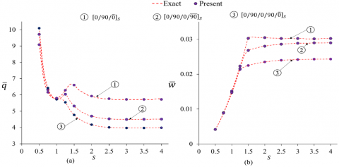
Figure 2. The non-dimensionalized (a) First ply failure with respect to S, (b) Central deflection with respect to S
The results of the exact solution published in the literature [10] are taken to validate the results of the formulation presented in this work. The material considered is GFRP and the properties are given in Table 1. The non-dimensional FPF loads based on present formulation are presented and compared with results of exact solution in Table 2. The non-dimensional FPF loads and transverse deflections calculated based on Tsai-Hill failure theory for different width to length (S=b/a) ratios are presented in Figure 2. The very close proximity of existing formulation results with the exact solution results validated the usefulness of the formulation.
4.2 Application on FMLs
Case-1: Aluminium-GFRP Laminate
Two configurations GLARE $[A l / 0 / 90 / \overline{A l}]_{S}$ and $[A l / 90 / 0 / \overline{A l}]_{S}$ have been considered for analysis for the non-dimensionalized FPF, the results so obtained for various failure criteria are presented in Figure 3.
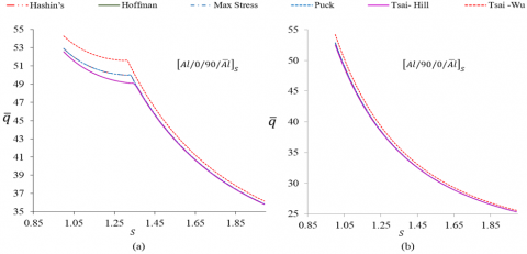
The results have shown that all the failure criterion have predicated more or less same failure loads. However, when width to length (S=b/a) between 0.85 to 1.85 are analyzed further as shown in Figure 4 In case of $[A l / 0 / 90 / \overline{A l}]_{S}$ the failure load predicated by Tsai-Wu criterion has been found to be more compared to other presented failure criterion. While failure load obtained by Tsai Hill and Hoffman are lowest. Whereas failure load obtained by maximum stress and puck failure criteria lies in between them. All the failure criterion has predicted the failure in the top of the first composite layer since this layer is more stressed as compared to the other layers
After S$\geq 1.33$. Failure was reported in second GFRP lamina. This behavior of shifting in the failure position is exhibited as nick in the Figure 4 (a). the larger slope after the nick indicates failure at low loads due to orientation of fibre in second GFRP layer along the large span [8].
Whereas in case of $[A l / 90 / 0 / \overline{A l}]_{S}$ for S$\geq 0.625$ failure reported at the top of the second GFRP after this aspect ratio top surface of first GFRP lamina failed. In this case also Tsai-Wu overestimated the failure load compared to other failure criterion. In this case also Tsai-Wu overestimated the failure load compared to other failure criterion. The change of slope has happened in this case at b/a=0.625 and has negligible influence on the slope of the curve because of laminate configuration and consequent stress distribution.
Figure 3. Non- dimensionalized FPF load with respect to (S) for Aluminium-GFRP Laminate for various failure criterion
Figure 4. Non-dimensionalized FPF load with plate aspect ratio (S) for Al-GFRP Laminate for various failure criterion
Case-2. Magnesium-GFRP Laminate
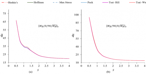
Numerical computation of different configurations of cross ply Magnesium-GFRP Laminate has been undertaken for analysis. Comparison of various failure criterion for different aspect ratios, are represented in Figure 5. In the range, $0.5 \leq S \leq 1$ $[M g / 90 / 0 / \overline{M g}]_{S}$ FPF load is more compare to $[M g / 0 / 90 / \overline{M g}]_{S}$, All the failure criterion shows that both the FMLs fails at more or less at same load. In case of $[M g / 0 / 90 / \overline{M g}]$ up to aspect ratio $S \leq 1.25$ The failures are observed at top of the first GFRP layer. While for $S \geq 1.250$ failure occurred in the top surface of the second GFRP laminate i.e. (90° of second GFRP lamina). For $[M g / 90 / 0 / \overline{M g}]_{S}$ failure occurred in the second GFRP (i.e.0°) layer at the top surface up to $S \leq 0.750$. after this $S \geq 0.875$ failure noted in the top of the first GFRP (i.e. in 90°). For both configurations Tsai-Wu overestimated the FPF load compared other failure criterion.
Figure 5. Non-dimensionalized FPF load with plate aspect ratio (S) for Mg-GFRP Laminate for various failure criterion
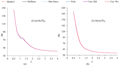
Figure 6. Non-dimensionalizedFPF load with plate aspect ratio (S)for Titanium-GFRP Laminate for various failure criterion
Case-3 Titanium GFRP Laminate
Two configurations of Ti-GFRP based FMLs have been analyzed, various failure criterion used to calculate the FPF. It has been observed that all the failure criteria yield more or less the same FPF. The non-dimensionalized FPF loads for various failure criterion are presented in Figure $6 .$ for $S \leq 1.5, \mathrm{FPF}$ for $\left[T i / 90 / 0 / \bar{T}_{l}\right]_{S}$ has higher than $\left[T i / 0 / 90 / \bar{T}_{l}\right]_{S}$. All failure criterion indicates that failure in the $\left[T i / 0 / 90 / \bar{T}_{l}\right]_{S}$ for $S \leq$ 1.25 occurred in the top of the first GFRP, whereas for $S \geq$ 1.5 failure occurred in the third laminate of GFRP., similarly in $\left[T i / 90 / 0 / \bar{T}_{l}\right]_{S}$ failure occurred at the top of the third GFRP laminate for $\mathrm{S} \leq 0.625,$ whereas after $\mathrm{S} \geq 0.750 \mathrm{FPFs}$ noted in the top of the first GFRP.
The need of the analysis when FMLs are subjected to lateral loads is established. A numerical approximation method has been developed and validated to predict the behavior of FMLs as simply supported rectangular plate subjected to uniformly distributed load.
The results are presented as non-dimensionalized quantities for proper comparison across various aspect ratios. Various failure criterions are studied to understand their influence on the results. From the results the following conclusions are arrived.
The failure loads obtained by numerical technique used for various failure criteria has an excellent correlation with results obtained by exact (Navier’s) solution.
All failure criterion shows for an aspect ratio less than 1, higher strength can be obtained by placing GFRP lamina perpendicular to principal axis at top and bottom of the laminate.
Results from comparison of different failure criterion has shown that all the theories are very close in their approximations. Tsai-Hill failure Criterion is recommended based on its wide application in the failure analysis of composite materials.
|
$w_{o}(x, y)$ |
Central deformation |
|
$S_{i T}, S_{i C}(i=1,2,3)$ |
Lamina strength along direction i in the tension and compression |
|
$S_{i j}(i \neq j ; i, j=1,2,3)$ |
Lamina shear strength on the plane i-j |
|
q(x,y) |
Transverse uniformly distributed load on the surface of the plate |
|
$\bar{q}$ |
Non-dimensional first Ply failure |
|
$\bar{w}$ |
Non-dimensional deformation |
|
$E_{i}(i=1,2,3)$ |
Modulus of Elasticity of lamina along the material principal direction. |
|
$G_{i j}(i \neq j ; i, j=1,2,3)$ |
Shear modulus of lamina in planes |
|
$D_{i j}(i, j=1,2,3)$ |
Bending Stiffness of a lamina |
|
a,b,h |
Length, width, and thickness of a laminate |
|
Greek symbols |
|
|
$\psi_{m}(x)$ |
Approximate function depending upon boundary conditions |
|
$\sigma_{i}(i=1,2)$ |
Stress in the principal direction. |
[1] Carrillo, J.G., Gonzalez-Canche, N.G., Flores-Johnson, E.A., Cortes, P. (2019). Low velocity impact response of fibre metal laminates based on aramid fibre reinforced polypropylene. Composite Structures, 220: 708-716. https://doi.org/10.1016/j.compstruct.2019.04.018
[2] Roebroeks, G.H.J.J. (1994). Fibre-metal laminates: Recent developments and applications. International Journal of Fatigue, 16(1): 33-42. https://doi.org/10.1016/0142-1123(94)90443-X
[3] Chandrasekar, M., Ishak, M.R., Jawaid, M., Leman, Z., Sapuan, S.M. (2017). An experimental review on the mechanical properties and hygrothermal behaviour of fibre metal laminates. Journal of Reinforced Plastics and Composites, 36(1): 72-82. https://doi.org/10.1177/0731684416668260
[4] Liu, C., Du, D., Li, H., Hu, Y., Xu, Y., Tian, J., Tao, J. (2016). Interlaminar failure behavior of GLARE laminates under short-beam three-point-bending load. Composites Part B: Engineering, 97: 361-367. https://doi.org/10.1016/j.compositesb.2016.05.003
[5] Jakubczak, P., Bieniaś, J., Dadej, K. (2020). Experimental and numerical investigation into the impact resistance of aluminium carbon laminates. Composite Structures, 244: 112319. https://doi.org/10.1016/j.compstruct.2020.112319
[6] Rao, P.M., Subba Rao, V.V. (2010). Estimating the failure strength of fiber metal laminates by using a hybrid degradation model. Journal of Reinforced Plastics and Composites, 29(20): 3058-3063. https://doi.org/10.1177%2F0731684409357257
[7] Xue, J., Wang, W.X., Zhang, J.Z., Wu, S.J., Li, H. (2015). Experimental and numerical study on the tensile behaviour of UACS/Al fibre metal laminate. Applied Composite Materials, 22(5): 489-505. https://doi.org/10.1007/s10443-014-9419-y
[8] Rao, N.N., Rao, P.M. (2019). First ply failure analysis of rectangular fiber metal laminated composite plates subjected to uniformly distributed loads. Journal of Failure Analysis and Prevention, 19(6): 1683-1690. https://doi.org/10.1007/s11668-019-00768-x
[9] Turvey, G.J. (1980). An initial flexural failure analysis of symmetrically laminated cross-ply rectangular plates. International Journal of Solids and Structures, 16(5): 451-463. https://doi.org/10.1016/0020-7683(80)90043-8
[10] Turvey, G.J. (1982). Uniformly loaded, antisymmetric cross-ply laminated, rectangular plates: An initial flexural failure analysis. Fibre Science and Technology, 16(1): 1-10. https://doi.org/10.1016/0015-0568(82)90010-0
[11] Ramtekkar, G.S., Desai, Y.M., Shah, A.H. (2004). First ply failure of laminated composite plates-a mixed finite element approach. Journal of Reinforced Plastics and Composites, 23(3): 291-315. https://doi.org/10.1177/0731684404031464
[12] Rao, P.M., Subba Rao, V.V. (2011). Degradation model based on Tsai-Hill factors to model the progressive failure of fiber metal laminates. Journal of Composite Materials, 45(17): 1783-1792. https://doi.org/10.1177/0021998310387682
[13] Smolnicki, M., Stabla, P. (2019). Finite element method analysis of fibre-metal laminates considering different approaches to material model. SN Applied Sciences, 1(5): 1-7. https://doi.org/10.1007/s42452-019-0496-2
[14] Reddy, J.N. (2003). Mechanics of Laminated Composite Plates and Shells: Theory and Analysis. CRC press.
[15] Laliberte, J., Poon, C., Straznicky, P.V., Fahr, A. (2000). Applications of fiber-metal laminates. Polymer Composites, 21(4): 558-567. https://doi.org/10.1002/pc.10211
[16] Ali, A., Pan, L., Duan, L., Zheng, Z., Sapkota, B. (2016). Characterization of seawater hygrothermal conditioning effects on the properties of titanium-based fiber-metal laminates for marine applications. Composite Structures, 158: 199-207. https://doi.org/10.1016/j.compstruct.2016.09.037
[17] Vermeeren, C.A.J.R. (2003). An historic overview of the development of fibre metal laminates. Applied Composite Materials, 10(4): 189-205. https://doi.org/10.1023/A:1025533701806
[18] Alderliesten, R. (2017). Fatigue and Fracture of Fibre Metal Laminates. 236. New York, USA: Springer.
[19] Ray, C., Satsangi, S.K. (1999). Laminated stiffened plate-a first ply failure analysis. Journal of Reinforced Plastics and Composites, 18(12): 1061-1076. https://doi.org/10.1177/073168449901801201
[20] Lee, C.S., Kim, J.H., Kim, S.K., Ryu, D.M., Lee, J.M. (2015). Initial and progressive failure analyses for composite laminates using Puck failure criterion and damage-coupled finite element method. Composite Structures, 121: 406-419. https://doi.org/10.1016/j.compstruct.2014.11.011
[21] Ferrante, L., Sarasini, F., Tirillò, J., Lampani, L., Valente, T., Gaudenzi, P. (2016). Low velocity impact response of basalt-aluminium fibre metal laminates. Materials & Design, 98: 98-107. https://doi.org/10.1016/j.matdes.2016.03.002
[22] Jakubczak, P., Bieniaś, J., Dadej, K. (2020). Experimental and numerical investigation into the impact resistance of aluminium carbon laminates. Composite Structures, 244: 112319. https://doi.org/10.1016/j.compstruct.2020.112319
[23] Nassir, N.A., Birch, R.S., Cantwell, W.J., Sierra, D.R., Edwardson, S.P., Dearden, G., Guan, Z.W. (2020). Experimental and numerical characterization of titanium-based fibre metal laminates. Composite Structures, 245: 112398. https://doi.org/10.1016/j.compstruct.2020.112398
[24] Sun, J., Daliri, A., Lu, G., Ruan, D., Lv, Y. (2019). Tensile failure of fibre-metal-laminates made of titanium and carbon-fibre/epoxy laminates. Materials & Design, 183: 108139. https://doi.org/10.1016/j.matdes.2019.108139