OPEN ACCESS
This research describes numerical investigations on the impacts of inner radius (bottom r1) on the thermal capability (heating and cooling) of the vortex tube and the heat and mass transfer between the cold and hot vortex cores inside a Ranque-Hilsch vortex tube applying the 3D CFD models. The cooling and heating capabilities increase severely with an increase in r1 value upto 1.5 mm (optimum value) and beyond this optimal value the thermal effectiveness of vortex tube decreases. The results have been compared to the experimental values with good agreement (less than 7 %).
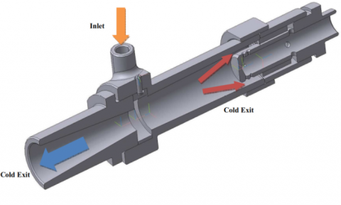
vortex tube, inner radiuses, heat transfer, energy separation
Vortex tube was explored or invented based on an accidental investigation by Ranque [1]. Several years later a German scientist [2] directed his efforts on improving this amazing device and vortex tube was introduced academically for the first time in 1947. As seen in Figure. 1, a vortex tube includes different parts such as: one or more inlet nozzles, a vortex-chamber, a cold end orifice, a throttle valve that is located at the end of main tube and a working tube. When pressured fluid is entered into the vortex-chamber tangentially via the nozzles, a strong rotational flow field is created. When the fluid tangentially swirls to the center of the vortex tube it is expanded and cooled. After occurrence of the energy separation in the vortex tube the pressured inlet fluid stream was divided into two different fluid streams including hot and cold exhaust fluids. The “cold exit or cold orifice” is located at near the inlet nozzles and at the other side of the working tube there is a changeable stream restriction part namely the control or throttle valve which determines the mass flow rate of hot exit. a percent of the compressed gas escapes through the valve at the end of the working tube as hot stream and the remaining gas returns in an inner swirl flow and leaves through the cold exit orifice. Opening the throttle valve reduces the cold airflow and closing the valve increases the cold mass flow ratio. Some of investigations on various aspects of vortex tubes are briefly mentioned below. Dutta et al. [3] performed a numerical study on energy separation inside a simple vortex tube. In their work a three dimensional Computational Fluid Dynamics (CFD) model is applied to study the phenomena of energy separation in a vortex tube with compressed air at normal atmospheric temperature and cryogenic temperature as the working fluid. Also in this work the NIST real gas model is employed for the first time to accurately compute the thermodynamic and transport properties of working fluid inside the vortex tube. Mohammadi et al. [4] carried out an experimental study to optimize the vortex tube parameters. In their study, a simple vortex tube with various parts is employed to obtain the optimum nozzle intake numbers and diameter. The influence of inlet pressure and cold mass fraction are also studied. Results illustrate that increasing the nozzle numbers causes a temperature drop and the optimum nozzle diameter corresponds to quarter of working tube diameter. The heat and mass transfer between the cold and hot cores (inside the vortex tube) is analyzed by Rafiee and Sadeghiazad [5]. The capabilities of different turbulence models (the RSM, LES, k–ω, k–ɛ and SST k–ω) for predicting the flow structures within the air separator were examined by Baghdad et al. [6] and Rafiee and Sadeghiazad [7]. Rafiee and Rahimi [8] studied the thermal performance of vortex tubes with different inlet temperature. Pourmahmoud et al. [9] analyzed the effect of shell heat transfer on vortex tube performance. Pourmahmoud et al. [10] determined the optimum value for the length of vortex tube. Some variations in the temperature drops are seen when a bended main tube is used in the structure of the air separator. These variations are reported in comparison with the air separator equipped with the straight main tube [11]. The effect of divergent main tube has been investigated by Rahimi et al. [12] and the optimum angle for the divergent main tube has been achieved numerically. Some factors regarding the vortex tube structure (the inlet of slots, the ratio of slots, the hot and cold exit area, the rounding off edge radius, the internal radius of main tube and the convergent slots) were optimized by Rafiee et al. [13], Rafiee and Sadeghiazad [14] and Pourmahmoud et al. [15]. Some refrigerant gases (R728, R32, R134a, R161, R744, and R22) have been examined in the vortex tube air separator and the thermal performance of air separator has been studied and the best refrigerant gas has been determined [16-17]. Rafiee and Sadeghiazad [18] analyzed the effect of different boundary conditions (pressure outlet and pressure far field) at the outlets and different working gases on the energy separation inside a vortex tube. Rafiee and Sadeghiazad [19-20] managed some experimental setups to optimize the control valve structural parameters such as the conical angle and the cone length and proved that there are some optimized values which lead to the best thermal capability. The impact of a new shape of the hot tube (the convergent main tube) is experimentally tested by Rafiee et al. [21] and Rafiee and Sadeghiazad [22-26]. Their results stated that there is an optimized angle for the convergent main tube to produce the best cooling capacity. Rafiee and Sadeghiazad [27] proposed a new energy explanation to analyze the thermal distribution and the exergy density inside the air separator applying the measured flow factors along the hot tube. The thermophysical parameters inside the vortex tube are comprehensively reported by Rafiee and Rahimi [28]. A comprehensive study was done to analyze the isotope separation using vortex tubes by Lorenzini et al. [29]. The effect of shape of control valve is analyzed by Rafiee and Sadeghiazad [30]. The effect of inlet temperature on the VT performance is evaluated by Pourmahmoud et al. [31]. Vortex tubes can help to separate the articles from the air. The air climate and related energy is investigated by Alberto Mirandola and Enrico Lorenzini [32].
Figure 1. A schematic drawing of Ranque-Hilsch vortex tube
The performance measurements on the VT systems (usually) are pointed and presented based on the temperature differences (there is no difference what kind of the VT is used, RHVT, PVT). There are three definitions; first, the cold temperature difference or $\Delta T_{\text { cold }}$ (difference between cold and inlet sides), the total temperature difference or $\Delta T$ (difference between cold and hot sides) and the hot temperature difference or $\Delta T_{\text { hot }}$ (difference between hot and inlet sides), these definitions are as bellow:
$\Delta T_{h}=T_{h}-T_{\text {inlet}}$ (1)
$\Delta T_{C}=T_{i n l e t}-T_{C}$ (2)
The 3D CFD model is created on basis of that was used by Skye et al. [33] in their experimental work. It is noteworthy that, an ExairTM 708 slpm vortex tube was used by Skye et al. [33] to perform all tests and to take all of the experimental data. Figure. 2 shows the geometrical parameters of the vortex tube which is under optimization. The 3D CFD mesh grid is shown in Figure. 3. In this model a regular organized mesh grid has been used. All radial line of this model of meshing has been connected to the centerline and the circuit lines have been designed organized from wall to centerline. So, the volume units that have been created in this model are regular cubic volumes. This meshing system helps the computations to be operated faster than the irregular and unorganized meshing, and the procedure of computations have been done more precisely.
Figure 2. Schematic of vortex tube
For this reason the CFD model has been assumed a rotational periodic condition. Hence, only a sector of the flow domain with angle of 60° needs to consider for computations as shown in Figure 3.
Figure 3. 3D CFD model of vortex chamber
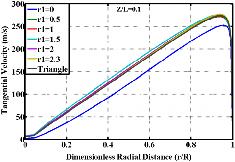
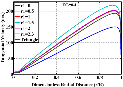
The numerical results achieved from the model, which involve the effect of edge radius change on different vortex tube parameters, are presented in this section. Although the separation at both exits is affected by the change in the edge radius inside the vortex-chamber, it is the cold exit temperature separation that is of special interest to us, owing to the potential industrial applications for gas flows of such low temperatures. In order to demonstrate the effect of edge radius change on radial profiles of tangential velocity, the profiles at three axial locations (Z/L= 0.1, 0.4, and 0.7) at the cold mass fraction 0.3 were analyzed, the diagrams of which are depicted in Figure.4. As seen in these Figureures, a vortex-chamber with a radius edge creates a larger magnitude of tangential velocity in comparison with a vortex-chamber without a radius edge in the critical zone. The diagrams show that at Z/L= 0.1 (near the chamber), the magnitude of tangential velocity at r1=2, 2.3 and 1.5 is greater than its value at r1=0, 0.5, 1 and triangle model.
Figure 4. Radial profile of tangential velocity at Z/L=0.1, Z/L=0.4 and 0.7 for ε =0.3
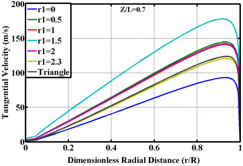
In Figureure 4, the radial profiles for the tangential velocity at Z/L= 0.1, 0.4, and 0.7 are provided for all of the created models. The swirl (tangential) velocity magnitude decreases as we move towards the hot end exit. This is clearly observable that the tangential velocity magnitude in the model of r1=1.5 is the greatest swirl velocity among the all of created models. The radial profile of the tangential velocity shows a free vortex near the wall. On the other hand, another, forced, vortex is formed in the core, in which swirl velocity values decrease as we move towards the centerline of working tube.
The total temperature variations for different edge radiuses at the three axial locations Z/L= 0.1, 0.4, and 0.7 are presented in Figure 5.
Figure 5. Radial profile of total temperature at Z/L=0.1, Z/L=0.4 and 0.7 for ε =0.3
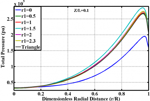
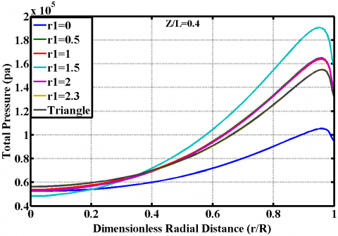
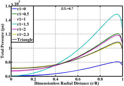
For all the edge radiuses, the maximum total temperature occurred near the periphery of the tube wall. The low temperature zone in the core coincides with the negligible tangential velocity zone. At the all of axial locations, the centerline total temperature in case (c1) has the lowest magnitude among the created models. This means that; a vortex tube which have a vortex-chamber with the edge radius r1=1.5 can create a colder stream than common produced models. As shown in temperature Figureures, the common model of vortex chamber (r1=0) is not an efficient model. Figureure 6 show the total pressure variations for different edge radiuses at the three axial locations Z/L= 0.1, 0.4, and 0.7 as a function of dimensionless radial distance of working tube. The maximum total pressure is observed near the periphery of the tube wall.
Figure 6. Radial profile of total pressure at Z/L=0.1, Z/L=0.4 and 0.7 for ε =0.3
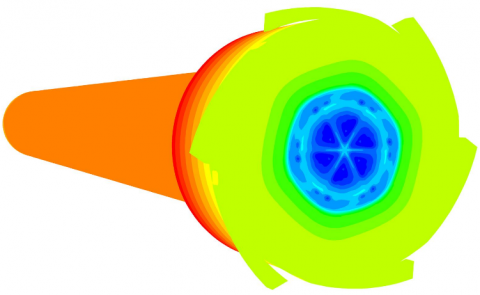
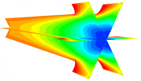
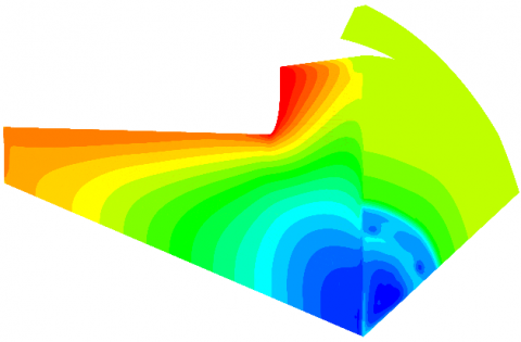
As seen in Figure. 6, fluid stream has greater total pressure in case (c1) in comparison with other cases. Figureure 6 demonstrates that the case (c1) has better swirl velocity, total pressure and the efficient total temperature than other cases. Case (c1) has lower cold exit temperature than the other models. So case (c1) is the efficient case. Figure. 7 shows the total temperature contour of optimal model.
Figure 7. Total temperature contour of optimized model
An optimization model of vortex-chamber has been modeled in this paper. We developed a 3D computational fluid dynamic model to simulate a vortex-chamber of vortex tube. Some changes have been implemented on vortex-chamber’s geometry and the effect of these changes has been studied to achieve the better performance of vortex tube. Primitive results have been validated with Skye et al.’s experimental data and show a good agreement with these results. The existence of edges at point 1 and 2 inside the vortex-chamber is an effective parameter of vortex tube’s performance. Optimized value of r1 at point 1 has been determined and that is 1.5 mm.
[1] Ranque GJ. (1933). Experiments on expansion in a vortex with simultaneous exhaust of hot air and cold air. Le J. de Physique et le Radium 4: 112-114.
[2] Hilsch R. (1947). The use of expansion of gases in a centrifugal field as a cooling process. Rev Sci Instrum. 18: 108-113. https://doi.org/10.1063/1.1740893
[3] Dutta T, Sinhamahapatra KP, Bandyopadhyay SS. (2011). Numerical investigation of gas species and energy separation in the Ranque–Hilsch vortex tube using real gas model. Int. J. Refrigeration 26(8): 2118-2128.
[4] Mohammadi S, Farhadi F. (2013). Experimental analysis of a Ranque–Hilsch vortex tube for optimizing nozzle numbers and diameter. Applied Thermal Engineering 61(2): 500-506.
[5] Rafiee SE, Sadeghiazad MM. (2016). Heat and mass transfer between cold and hot vortex cor,es inside ranque-hilsch vortex tube-optimization of hot tube length. International Journal of Heat and Technology 34(1): 31-38. https://doi.org/10.18280/ijht.340105
[6] Baghdad M, Ouadha A, Imine O, Addad Y. (2011). Numerical study of energy separation in a vortex tube with different RANS models. Int. J. Thermal Sciences 50(12): 2377-2385. https://doi.org/10.1016/j.ijthermalsci.2011.07.011
[7] Rafiee SE, Sadeghiazad MM. (2016). Three-dimensional computational prediction of vortex separation phenomenon inside Ranque-Hilsch vortex tube. Aviation 20(1): 21-31. https://doi.org/10.3846/16487788.2016.1139814
[8] Rafiee SE, Rahimi M. (2013). Experimental study and three-dimensional (3D) computational fluid dynamics (CFD) analysis on the effect of the convergence ratio, pressure inlet and number of nozzle intake on vortex tube performance-Validation and CFD optimization. Energy 63: 195-204. https://doi.org/10.1016/j.energy.2013.09.060
[9] Pourmahmoud N, Abbaszadeh M, Rashidzadeh M. (2016). Numerical simulation of effect of shell heat Transfer on the vortex tube performance. International Journal of Heat and Technology 34(2): 293-301. https://doi.org/10.18280/ijht.340220.
[10] Pourmahmoud N, Esmaily R, Hassanzadeh A. (2015). CFD investigation of vortex tube length effect as a designing criterion. International Journal of Heat and Technology 33(1): 129-136. https://doi.org/10.18280/ijht.330118
[11] Rafiee SE, Ayenehpour S, Sadeghiazad MM. (2016). A study on the optimization of the angle of curvature for a Ranque–Hilsch vortex tube, using both experimental and full Reynolds stress turbulence numerical modeling. Heat and Mass Transfer 52(2): 337-350.
[12] Rahimi M, Rafiee SE, Pourmahmoud N. (2013). Numerical investigation of the effect of divergent hot tube on the energy separation in a vortex tube. International Journal of Heat and Technology 31(2): 17-26.
[13] Rafiee SE, Rahimi M, Pourmahmoud N. (2013). Three-Dimensional numerical investigation on a commercial vortex tube based on an experimental model- part I: optimization of the working tube radius. International Journal of Heat and Technology 31(1): 49-56.
[14] Rafiee SE, Sadeghiazad MM. (2015). 3D numerical analysis on the effect of rounding off edge radius on thermal separation inside a vortex tube. International Journal of Heat and Technology 33(1): 83-90.
[15] Pourmahmoud N, Hasanzadeh A, Rafiee SE, Rahimi M. (2012). Three-dimensional numerical investigation of effect of convergent nozzles on the energy separation in a vortex tube. International Journal of Heat and Technology 30(2): 133-140.
[16] Pourmahmoud N, Rafiee SE, Rahimi M, Hasanzadeh A. (2013). Numerical energy separation analysis on the commercial Ranque-Hilsch vortex tube on basis of application of different gases. Scientia Iranica 20(5): 1528-1537.
[17] Rafiee SE, Sadeghiazad MM. (2016). Three-dimensional CFD simulation of fluid flow inside a vortex tube on basis of an experimental model- the optimization of vortex chamber radius. International Journal of Heat and Technology 34(2): 236-244. https://doi.org/10.18280/ijht.340212
[18] Rafiee SE, Sadeghiazad MM. (2016). Three-dimensional numerical investigation of the separation process inside vortex tube using different operating conditions. Journal of Marine Science and Application 06: 1-10. https://doi.org/10.1007/s11804-016-1348-8
[19] Rafiee SE, Sadeghiazad MM. (2014). Effect of conical. valve angle on cold-exit temperature of vortex tube. Journal of Thermophysics and heat transfer 28: 785-794. https://doi.org/10.2514/1.T4376
[20] Rafiee SE, Sadeghiazad MM. (2014). Three-dimensional and experimental investigation on the effect of cone length of throttle valve on thermal performance of a vortex tube using k–ɛturbulence model. Applied Thermal Engineering, 66(1–2): 65–74. https://doi.org/10.1016/j.applthermaleng.2014.01.073
[21] Rafiee SE, Sadeghiazad MM, Mostafavinia N. (2015). Experimental and numerical investigation on effect of convergent angle and cold orifice diameter on thermal performance of convergent vortex tube. J. Thermal Sci. Eng. Appl. 7(4). https://doi.org/10.1115/1.4030639
[22] Rafiee SE, Sadeghiazad MM. (2017). Efficiency evaluation of vortex tube cyclone separator. Applied Thermal Engineering 114(5): 300–327. https://doi.org/10.1016/j.applthermaleng.
[23] Rafiee SE, Sadeghiazad MM. (2017). Experimental and 3D-CFD investigation on optimization of the air separator structural parameters for maximum separation efficiency. Separation Science and Technology 52(5): 903-929. https://doi.org/10.1080/01496395.2016.1267755
[24] Rafiee SE, Sadeghiazad M.M. (2016). Experimental study and 3D CFD analysis on the optimization of throttle angle for a convergent vortex tube. Journal of Marine Science and Application 15(4): 388–404. https://doi.org/10.1007/s11804-016-1387-1
[25] Rafiee SE, Sadeghiazad MM. (2016). Experimental and 3D-CFD study on optimization of control valve diameter for a convergent vortex tube. Frontiers in Heat and Mass Transfer 7(1): 1-15. https://doi.org/10.5098/hmt.7.13
[26] Rafiee SE., Sadeghiazad MM. (2016). Experimental and 3D CFD investigation on energy separation inside a convergent vortex tube air separator. Scientia Iranica 23(4).
[27] Rafiee SE, Sadeghiazad MM. (2014).3D CFD exergy analysis of the performance of a counter flow vortex tube, International Journal of Heat and Technology 32(1-2): 71-77.
[28] Rafiee SE, Rahimi M. (2014). Three-dimensional simulation of fluid flow and energy separation inside a vortex tube. Journal of Thermophysics and Heat Transfer 28: 87-99. https://doi.org/10.2514/1.T4198
[29] Lorenzini E, Spiga M. (1982). Aspetti fluidodinamici della separazione isotopica mediante tubi a vortice di Hilsch Ingegneria 121-126 (maggio-giugno).
[30] Rafiee SE, Sadeghiazad MM. (2017). Experimental and 3D CFD investigation on heat transfer and energy separation inside a counter flow vortex tube using different shapes of hot control valves. Applied Thermal Engineering 110: 648-664.
[31] Pourmahmoud N, Rahimi M, Rafiee SE, Hassanzadeh A, (2014) A numerical simulation of the effect of inlet gas temperature on the energy separation in a vortex tube. Journal of Engineering Science and Technology 9(1): 81-96.
[32] Mirandola A, Lorenzini E. (2016). Energy, environment and climate: from the past to the future. International Journal of Heat and Technology 34(2): 159-164. https://doi.org/10.18280/ijht.340201
[33] Skye HM, Nellis GF, Klein SA. (2006). Comparison of CFD analysis to empirical data in a commercial vortex tube. Int. J. Refrig 29: 7180. https://doi.org/10.1016/j.ijrefrig.2005.