Abdelrahman Youssef | Amgad M. Bayoumy* | Mostafa R.A. Atia
© 2021 IIETA. This article is published by IIETA and is licensed under the CC BY 4.0 license (http://creativecommons.org/licenses/by/4.0/).
OPEN ACCESS
Although the Delta robot has many applications in pick-and-place operations, some problems limit its use. The difficult programming is one of these limitations. Parallel robot programming depends on solving the forward and inverse kinematics equations of the robot. These equations relate the geometric parameters, such as length and angle of every robot arm, to the position of the end effector and vice versa. The kinematic equations are hard to be derived. Moreover, any change in the robot geometry, due to a change in the application condition, requires that new kinematic equations be derived. This needs a very sophisticated and specialized programmer, who is not always available. Consequently, this problem limits the use of parallel robots. This paper discusses the use of ANN and embedded systems in addition to stereo vision to command delta robot in pick-and-place operations. The method is implemented and tested giving satisfactory results.
parallel robot, delta robot, neural networks, artificial intelligence, pick and place, forward kinematics, inverse kinematics
Since most of the manufacturing is heading towards smarter facilities and human free operators, Delta robots have the lead in a lot of pick and place applications because of its accuracy, speed, and heavy payload it can carry. However, its drawback is that an expert in robotics is not always available. Moreover, programming such a robot is a challenge that is not only time-consuming, but could also end up with a lot of error.
Professor Reymond Clavel is the leader behind using the parallelograms to build his first Delta robot; he used three rotational joints and one translational joint. The reason behind his design was to find speed as well as an accurate method to handle light objects. He won the Golden robot award upon his creation in 1999. From this time, every company was searching for a new technique for handling pick-and-place tasks. One of the lead companies in manufacturing this kind of robots is ABB for Robotics [1].
The Delta robot can carry a much higher payload than a serial one. On top of that, its accuracy in reaching the target point is much better. The Delta robot can be divided into two main categories: planner motion and 3d motion which depend on its configuration with the actuators [2].
Ali Rouhollahi used a 4 degree of freedom (DOF) parallel robot called Quattro, and a vision was attached to the robot for object detection. Objects were delivered through a conveyor system. The position of the end effector depends on the motion of the servo; therefore, he used a PID controller [3].
Roshni N mentioned that teaching robots where is the object is essential for pick and place. Teaching is done by machine vision integrated with sensors. Roshni focused on how to alter the difference between the target object and obstacle, and finally, how to grasp a moving target successfully. The proposed technique was done using the ABB IRB 1200 robot [4].
Özkan established a 5 DOF closed kinematics chain robot that is in charge of injecting small creatures using needles. His technique improved the precision of the needle position by using a visual follower. He measured the accuracy of the system before using the optical follower and after it, and he found out that the error had decreased from 5mm to 0.4mm [5].
Daniel Chaparro-Altamirano proposed a method for obtaining the forward kinematics using a geometrical approach. He used Neural Networks and Newton Raphson to describe the workspace of the parallel robot [6].
Mahfuzah Mustafa had proposed a method that solves forward kinematics. This method is using a Spherical-Spherical joint pair. She stated that the arm of the delta robot moves in spherical motion, and that the intersection of the three-sphere is the position of the end-effector. Comparing the results with the actual position, she confirmed that they are the same [7].
Igor Gritsenko stated that there is a new method for calculating the Forward Kinematics (FK) of a Parallel Robot (PR), which relies on the verification of the analytical and the numerical method. This method had also shown its ability to calculate the workspace of the PR in about 150 microseconds [8].
Nima Karbasizadeh had stated that his main concern for his Delta robot was to know its kinematics. Therefore, he used a stereo-camera like Microsoft Kinect as a sensor; to know the position of the end effector [9].
M. Dehghani also expressed that it is challenging to obtain the FK because it is not the same as with the serial robot. She suggested a proper numerical technique for defining the FK for the HEXA robot that she used, and she also mentioned that this method has drawbacks, as it relies on achieving the convergence. That is why she suggested the usage of Neural Networks, which provide minimal modelling error [10].
Manuel Cardona used the numerical method to find the FK of Stewart-Gough PR. His analysis depended on placing the PR in a specific position and using the Newton Rhapshon method to estimate the location of the end-effector [11].
Pannawit Srisuk used a Neural Network to get the Inverse kinematics of a 3 DOF arm robot. The inputs for the ANN were the angles of rotation, and outputs were the cartesian coordinates. The proposed model consisted of 2 hidden layers. Srisuk claimed that his model is easy to implement, and that for more than 3 arms, the number of input neurons can be increased by one [12].
Fazeleh Tavassolian mentioned that FK is the key problem in every PR. The type of PR he used was planner, and he divided the PR workspace into subspaces. For each subspace, he used an ANN to estimate the position of the end-effector. The proposed model showed a reduction in memory requirement and needed less computational time [13].
Xinxin Guouse used a machine training method called the Elman Recurrent Network, which is used to extract the FK. The training sample was obtained by calculating the IK and the proposed model was applied on a Stewart delta robot. He mentioned that the trained model showed excellent performance [14].
This paper proposes a programming method for supervised learning using a Stereo camera on a robot whose target is to detect the object to be picked. A 3 DOF Delta robot has been manufactured, with sensors attached to its arms, to provide feedback for the angles of rotation. A calibration process has been accomplished using predefined positions. Then, the dataset to be used in the training process was generated. The generated algorithm has then been capable of moving the robot to the target object with fair accuracy. The proposed method could help in spreading the usage of delta robots in pick-and-place applications.
In the proposed approach, an ANN is trained using a dataset of the robot arm angles and the end effector position. The arm angles are measured by rotary resistive sensors. The end effector position is defined in cartesian coordinates using a stereo camera system. An image processing module is used to analyse the camera system output and define the end effector position. In this research, the ANN is designed, trained, and evaluated using a test rig. There are two approaches that are used to test the behavior of the ANN: either using a laptop or using a stand-alone embedded system like Raspberry-Pi Single Board Computer (RaPi SBC). As shown in Figure 1, the framework is constructed from RaPi, which is used to acquire images from the stereo camera. The stereo camera is connected to the RaPi using two USB ports. The acquired images are sent to the PC wirelessly. In addition, the MyRio data acquisition device is used as a data logger and an analog to digital converter (ADC) to record potentiometer readings corresponding to joint angles. These readings are fed to the 12-bit resolution ADC. This number of bits implies that the achieved resolution of the potentiometer readings are less than 0.05 step for one degree. In addition, a 9x7 checkerboard is used for camera caliberation by placing an object in predefined locations.
Figure 1. The proposed approach
2.1 Forward kinematics
For parallel delta robot, FK is very difficult to be obtained since it requires solving multiple coupled nonlinear equations. An alternate solution is to find the position of the end-effector using a trigonometric technique.
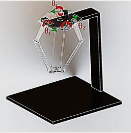
For the FK of the Delta robot, the given parameters are the angles of rotation of the joints ($\theta_{i}, i=1,2,3$) as shown in Figure 2, and it is required to calculate the position of the end effector [15].
Figure 2. Delta robot diagram
By applying the method that is used to calculate the inverse and forward kinematics based on Robert L. Williams solution [16], where the axes X0, Y0, and Z0 are obtained graphically using the Spherical-Spherical method, we find that:
$x_{0}=\left(a_{1} z_{0}+b_{1}\right) /\left(y_{2}-y_{1}\right) x_{3}-\left(y_{3}-y_{1}\right) x_{2}$
$y_{0}=\left(a_{2} z_{0}+b_{2}\right) /\left(y_{2}-y_{1}\right) x_{3}-\left(y_{3}-y_{1}\right) x_{2}$
$z_{0}=\frac{-b \pm \sqrt{\left(b^{2}-4 a c\right)}}{2 a}$
where:
$a_{1}=\frac{1}{d}\left[\left(z_{2}-z_{1}\right)\left(y_{3}-y_{1}\right)-\left(z_{3}-z_{1}\right)\left(y_{2}-y_{1}\right)\right]$
$a_{2}=\frac{1}{d}\left[\left(z_{2}-z_{1}\right) x_{3}-\left(z_{3}-z_{1}\right) x_{2}\right]$
$b_{1}=\frac{1}{2 d}\left[\left(w_{2}-w_{1}\right)\left(y_{3}-y_{1}\right)-\left(w_{3}-w_{1}\right)\left(y_{2}-y_{1}\right)\right]$
$b_{2}=\frac{1}{2 d}\left[\left(w_{2}-w_{1}\right) x_{3}-\left(w_{3}-w_{1}\right) x_{2}\right]$
$a=a 1^{2}+a 2^{2}+\left(y_{2}-y_{1}\right) x_{3}-\left(y_{3}-y_{1}\right) x_{2}$
$b=2\left(a_{1} b_{1}+a_{2}\left(b_{2}-y_{1}\left(\left(y_{2}-y_{1}\right) x_{3}-\left(y_{3}-y_{1}\right) x_{2}\right)\right.\right.$$\left.\quad-z_{1}\left(\left(y_{2}-y_{1}\right) x_{3}-\left(y_{3}-y_{1}\right) x_{2}\right)\right)^{2}$
$\begin{aligned} c=\left(b_{2}-y_{2}(\right.&\left.\left.\left(y_{2}-y_{1}\right) x_{3}-\left(y_{3}-y_{1}\right) x_{2}\right)\right)^{2}+b_{1}^{2} +\left(b_{2}-y_{2}\left(\left(y_{2}-y_{1}\right) x_{3}-\left(y_{3}\right.\right.\right.\left.\left.\left.-y_{1}\right) x_{2}\right)\right)^{2}\left(b_{1}^{2}-r_{e}^{2}\right) \end{aligned}$
The following table shows the parameters of the proposed delta robot (Table 1). Where: rf is the distance from the center of the actuators to intersection of the rod, re is the distance from the center of the joint on the end-effector to the rod, f is the side length of the base triangle, and e is side length of the end-effector.
Table 1. Delta Robot Kinematics parameters
|
Parameters |
Dimension in mm |
|
rf |
125 |
|
re |
265 |
|
f |
260 |
|
e |
139 |
2.2 Artificial Neural Networks
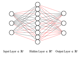
The new technology is heading towards making the robotics smarter, more able of modeling complex nonlinear behavior, and performing decision making. Artificial Neural Networks (ANNs) are introduced to simulate the learning behavior of humans. The main construction of the Neural Network can be divided into three layers, as shown in Figure 3.
Figure 3. Neural Network construction
The sequence of the proposed approach is:
The hardware is chosen such that it has the necessary components to implement the proposed approach and the common practice. Therefore, the experiments needed the following: (1) a lightweight robot with smart actuators, (2) an accurate machine vision that can generate RGB images and depth map of the environment, (3) object detection and distance measurements, (4) performing machine training, (5) end-effector tool to grasp detected object.
The operator moves the end-effector to a certain position; those positions should be detected using the stereo camera. The main aim of the machine vision is to obtain the X, Y and Z coordinates of that position. Next, the collected data will be used as a baseline that describes the workspace. On the other hand, the angles of motion are also recorded. This means that every position on the calibration sheet has a certain angle value. The more points are generated for the calibration, the better the workspace description is achieved.
The procedure is then repeated for 3 objects with different heights of values: 180, 130 and 100 mm. They are placed on a calibration sheet that has 15 points. Each object is placed at each point, then the position and angles are recorded and used for the Neural Network training.
3.1 Delta robot
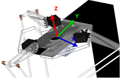
The Delta robot is designed using SOLIDWORKS 2017 as shown in Figures 4 and 5. The most important thing is to define the coordinate system for the Delta robot, which is going to be at the center of the plane passing through the shafts of the servos.
Figure 4. Delta robot origin
The design helps us in extracting the kinematics parameters.
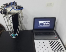
Figure 5. Delta robot setup
3.2 NI My-Rio 1900
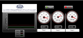
A graphical user interface was desgined to work as a data logger for the joint angles. This GUI was done using LabVIEW connected with My-Rio. The potentiometer reading is fed to the analog to digital converter (ADC) port of the My-Rio. The ADC has a resolution of 12 bits; therefore, a minimum change in potentiometer values will be less than 0.05 step for one degree. The GUI shows the measured angles according to the position of the end-effector as shown in Figure 6.
Figure 6. Graphical User Interface (GUI) for data logging for angle movement
3.3 Potentiometer
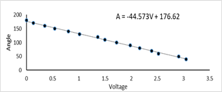
To measure angles of the servos, a potentiometer is placed in front of the shaft. The three potentiometers are rotary with 100 kOhms. The used potentiometer is a single turn. The terminals of the potentiometers are connected to My-Rio. The potentiometer could give a nonlinear response; therefore, it should be calibrated. Multiple readings are obtained by measuring the angle using a protractor. The data is then recorder with the voltage reading. Next, by performing curve fitting using excel, the linearized equation is be extracted as shown in Figure 7.
Figure 7. Potentiometer calibration
3.4 Machine vision
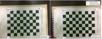
A stereo camera has been attached at the bottom of the fixed base of the Delta robot as shown. The function of the stereo camera is to make sure that we detected the object as well as to get the depth coordinates. The stereo camera is consisting of 2 RGB cameras with max resolution of 640*480 pixels and 30 frames per second (FPS). A machine vision calibration is performed to export calibration parameters for the stereo camera. This is done by printing an A4 checkerboard consisting of (7x9) squares, 20mm x 20mm each, as shown in Figure 8.
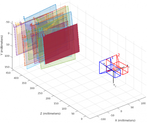
The results of the calibration process is shown in Figure 9. By the end of the calibration process, a file with camera parameters is exported. The parameters have multiple information about stereo vision. These include the rotation and translation of one camera with respect to the other one. The extrinsic parameters of the camera determine the location of the reference point, as it unifies the information given from the coordinate of the stereo image. This file of parameters is necessary for the triangulation process to detect the depth of the object. The final achieved accuracy is shown in Figure 10. As shown in figure, calibration error is less than 1 pixel.
Figure 8. Checkerboard for stereo calibration
Figure 9. Camera calibration
3.5 Raspberry Pi
The RPi SBC is used to acquire images from the stereo camera, which is connected to it using two USB ports. The acquired images are then sent to the PC wirelessly.
3.6 Datasets for the Neural Network Training
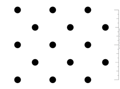
Before training the ANN, experimental data is needed to be collected. This is done by placing the target object in a certain location on top of the calibration sheet. The distance from the center of each circle is 32 mm in the x-direction and 32 mm in y direction as shown in Figure 11.
Three objects are placed on the 15 points of the calibration sheet. As a result, a 45 stereo image is acquired. The heights of the 3 objects are 180 mm, 130 mm, and 100 mm respectively.
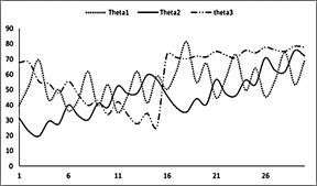
By moving the end-effector to the specific location, the angles change, and have been recorded and plotted as shown in Figure 12.
Figure 10. Calibration error
Figure 11. Position calibration sheet
Figure 12. Angles movement
The collected data is divided into three datasets: training, validation and testing. For the machine training using the Neural Network on MATLAB, it is required to import input data and output data for the training. The input data for the training is the position of the detected object, and the output data is the measured angles of the actuators.
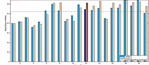
The proposed system has one hidden layer with 9 neurons, and the training function is Levenberg-Maraquardt. The performance of the proposed system is measured by the Mean Square Error as shown in Figure 13.
The relationship between the controlled input and output is shown in Figure 14 for the training, validation, and testing datasets. As shown in figure the correlation coefficient (R) is approximately one in all datasets.
In Figure 14, the three main graphs represent the training, validation, and testing datasets. The dashed line indicates the target, which is the difference between the perfect result and the output of the neural network. The R value indicates how far the output value is from the perfect result. It is clear that the R value is close to 1; this indicates that there is a linear relation between the output and the perfect result.
Figure 13. Neural Network construction
Figure 14. Artificial Neural Network regression
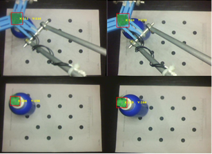
Training and testing the performance of the ANN on multiple objects with different heights were performed to reduce the position error, especially in the Z-direction. This was achieved by carrying out the sample generation process for the three different objects of different heights. The XYZ position and the joint angles were then obtained for every training location in the calibration sheet for each of the different objects. After that, the Neural Network performance was tested by placing the three objects in the different positions, then the end-effector was moved using output form the ANN. The position of the end effector was measured by the stereo camera (as shown in Figure 15) and the results were compared with the FK of the Delta robot. Table 2 shows the normalized errors over X, Y, and Z coordinates. These normalized errors are averaged over the total number of samples.
Figure 15. Acquired position of the object
Table 2. Normalized errors in X, Y, Z and all dimensions corresponding to number of samples
|
No. of Samples |
X |
Y |
Z |
All |
|
15 |
37 |
32 |
43.5 |
37.5 |
|
30 |
20.15 |
28 |
16 |
21.4 |
|
45 |
11.9 |
16.3 |
13 |
13.7 |
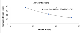
The number of samples with the required normalized error could be obtained using the equation in Figure 16.
Figure 16. Normalized error
From the results that have been obtained, the proposed approach can easily command a complex mechanism like that of the Delta robot without knowing the details of its FK. This technique does not require a pre-knowledge about design parameters, like the knee and hip of the Delta robot. On top of that, it is easy to be implemented as it only requires placing objects in multiple locations that define the boundaries of the workspace to enable the machine to get trained. The proposed approach shows fewer steps and consumes less programming time than the common ones. The impact of the errors resulting from the proposed approach on the pick-and-place is like the common practice, such as the programming of control point and robot mechanical issues. The normalized error of the position is decreased by increasing the number of samples for the training purposes. As a conclusion, the proposed method of programming delta robot could be a good alternative of existing methods.
The authors would like to thank Eng. Nadine Amr Mahmoud for critically reviewing this paper and providing many helpful comments.
[1] Pessina, L.A. Reymond Clavel, creator of the Delta Robot, reflects on his career. https://sti.epfl.ch/reymond-clavel-creator-of-the-delta-robot-reflects-on-his-career/, accessed on Sep. 18, 2021.
[2] Robotic carton/case loader debuts high speed pick-and-place applications 2014. https://www.packagingstrategies.com/articles/86823-robotic-cartoncase-loader-debuts-high-speed-pick-and-place-applications, accessed on accessed on Sep. 18, 2021.
[3] Rouhollahi, A., Azmoun, M., Masouleh, M.T. (2018). Experimental study on the visual servoing of a 4-DOF parallel robot for pick-and-place purpose. 2018 6th Iranian Joint Congress on Fuzzy and Intelligent Systems (CFIS), Kerman, Iran, pp. 27-30. https://doi.org/10.1109/CFIS.2018.8336617
[4] Roshni, N., Kumar, T.K.S. (2017). Pick-and-place robot using the centre of gravity value of the moving object. 2017 IEEE International Conference on Intelligent Techniques in Control, Optimization and Signal Processing (INCOS), Srivilliputtur, India, pp. 1-5. https://doi.org/10.1109/ITCOSP.2017.8303079
[5] Hwang, B.Ö., Hwang, M.J., Cavusoglu, M.C. (2013). Design of a parallel robot for needle-based interventions on small animals. IEEE/ASME Transactions on Mechatronics, 18(1): 62-73. https://doi.org/10.1109/TMECH.2011.2162427
[6] Chaparro-Altamirano, D., Zavala-Yoe, R., Ramirez-Mendoza, R. (2013). Kinematic and workspace analysis of a parallel robot used in security applications. 2013 International Conference on Mechatronics, Electronics and Automotive Engineering, Morelos, Mexico. https://doi.org/10.1109/ICMEAE.2013.6
[7] Mustafa, M., Misuari, R., Daniyal, H. (2007). Forward kinematics of 3 degree of freedom delta robot. 2007 5th Student Conference on Research and Development, Selangor, Malaysia, pp. 1-4. https://doi.org/10.1109/SCORED.2007.4451401
[8] Gritsenko, A., Seidakhmet, A., Abduraimov, A., Gritsenko, P., Bekbaganbetov, A. (2017). Delta robot forward kinematics method with one root. 2017 International Conference on Robotics and Automation Sciences (ICRAS), Hong Kong, China, pp. 39-42. https://doi.org/10.1109/ICRAS.2017.8071913
[9] Karbasizadeh, N., Masouleh, M.T., Kalhor, A. (2016). Experimental kinematic identification of a 3-DOF decoupled parallel robot using calibrated kinect sensor. 2016 4th International Conference on Robotics and Mechatronics (ICROM), Tehran, Iran, pp. 160-165. https://doi.org/10.1109/ICRoM.2016.7886839
[10] Dehghani, M., Ahmadi, M., Khayatian, A., Eghtesad, M., Farid, M. (2008). Neural network solution for forward kinematics problem of HEXA parallel robot. The 2008 American Control Conference, Seattle, WA, USA. https://doi.org/10.1109/ACC.2008.4587155
[11] Cardona, M. (2015). A new approach for the forward kinematics of general Stewart Gough platforms. 2015 IEEE Thirty Fifth Central American and Panama Convention (CONCAPAN XXXV), Tegucigalpa, Honduras, pp. 1-6. https://doi.org/10.1109/CONCAPAN.2015.7428478
[12] Srisuk, P., Sento, A., Kitjaidure, Y. (2017). Inverse kinematics solution using neural networks from forward kinematics equations. 2017 9th International Conference on Knowledge and Smart Technology (KST), Chonburi, Thailand, pp. 61-65. https://doi.org/10.1109/KST.2017.7886084
[13] Tavassolian, F., Khotanlou, H., Varshovi-Jaghargh, P. (2018). Forward kinematics analysis of a 3-PRR planer parallel robot using a combined method based on the neural network. 2018 8th International Conference on Computer and Knowledge Engineering (ICCKE), Mashhad, Iran, pp. 320-325. https://doi.org/10.1109/ICCKE.2018.8566243
[14] Guo, X., Ke, G., Zheng, F., Zhang, L. (2013). Forward kinematics analysis of the Stewart parallel platform based on the Elman recurrent network. 2013 5th International Conference on Intelligent Human-Machine Systems and Cybernetics, 2: 175-177. https://doi.org/10.1109/IHMSC.2013.189
[15] Staicu, S., Carp-Ciocardia, D.C. (2003). Dynamic analysis of Clavel’s Delta parallel robot. 2003 IEEE International Conference on Robotics and Automation (Cat. No.03CH37422), Taipei, Taiwan. https://doi.org/10.1109/ROBOT.2003.1242230
[16] Robot, A.F.D. (2016). The Delta Parallel Robot: Kinematics Solutions Robert L. Williams II, Ph. D., williar4@ ohio. edu Mechanical Engineering, Ohio University. https://www.ohio.edu/mechanical-faculty/williams/html/PDF/DeltaKin.pdf.