Adekunle T. Oyelami* | Samuel O.O. Olusunle
OPEN ACCESS
Spherical shapes are known to be the ideal theoretical profile for a vessel that resists internal pressure mainly because the tensile stresses developed at the wall of a pressurized spherical vessel is uniform in all directions. This makes a sphere very strong structure and the preferred shape for storing high pressure fluids since it is the only known shape that has no weak points. The major reason why spherical tanks are not commonly used is because of the complexity of the procedure for their development and the associated high cost of production. This work has successfully developed a relatively simplified framework for the design of the constituent sections of a spherical storage tank thereby providing a way out of the difficulty normally associated with its development. The framework developed was validated by using it to design and develop a 225 liter capacity spherical tank. Two models of same capacity were developed and evaluated. The first model was developed through 10-section members while the second model used 30-section members.
modeling, pressurized sections, sphere and stresses
A sphere is the optimal geometry for a closed pressure vessel in the sense of being the most structurally efficient shape. A cylindrical vessel is somewhat less efficient for two reasons: (1) the wall stresses vary with direction, (2) closure by end caps can alter significantly the ideal membrane state, requiring additional local reinforcements. However the cylindrical shape may be more convenient to fabricate and transport.
Spherical storage tanks are preferred for storage of high pressure fluids. A spherical tank is considered stronger than its counterparts such as the common fixed roof tank, open top tank, and floating roof tank [1-3]. The even distribution of stresses on the sphere's surfaces, both internally and externally, generally means that there are no weak points. Pressure inside a true spherical tank is known to be identical on every axis. Common storage tanks are comprised of numerous components or pieces of metal that are welded or bolted together, in the field or in the shop. Welds and seams are generally accepted as weak points in high pressure scenarios. The spherical shape creates great strength in resisting these pressures and offers the least amount of exterior surface, which reduces the transfer of warmer ambient temperatures on the overall volume. Spherical storage tanks are more expensive to fabricate than the other common types, and become more economically feasible as the tank design gets larger. Vertical cylindrical tanks resting on the ground are however sometimes used in lieu of spherical tanks on account of their low manufacturing cost and higher capacities [1].
Spherical tank finds great use in applications involving pressure vessels and pressure vessels have been in wide use for many years in petroleum, chemical, military industries and also in nuclear power plants [4, 5]. Other recorded uses of spherical tanks include storing of various liquids ranging from non-flammable liquids to dangerous flammable or toxic chemicals with explosive nature and are installed almost in each sector of contemporary industry like nuclear, energy, chemical etc. [3]. During ordinary operation, the liquid storage. They are known to be usually subjected to high pressures and temperatures which may be constant or cycling.
The conventional method of manufacturing spherical tanks/vessels involves forming of spherical petal blanks after which the petal blanks are fabricated and welded to make spherical vessel. An approach previously developed involves integral forming after fabrication and welding, in which the sheet metal will be first cut into predesigned shapes of flat blanks and thereafter fabricated and welded into a closed single-curvature shell [6]. The shell will then filled be with a liquid after which it will be hydro bulged where resulting internal pressure from the pressure pump will cause plastic deformation in the shell under the effect of the hastening-circle moment which promotes the tendency of an internally pressurized shell to be spherical.
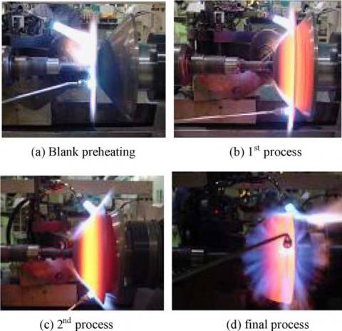
There were two other different procedures developed whereby pressure vessels can be manufactured. The first method was described as a process of spin forming and Tungsten Inert Gas (TIG) welding as shown in Figure 1 while the second method involved blow forming together with solid-state diffusion bonding process [7-9].
Another method for the design and manufacturing process of a spherical tank as described involved manufacturing by the dieless hydra-bulging technology involving cutting, roll-bending, assembling, welding, hydro-bulging, final inspecting and tempering [9].
Figure 1. Hot spinning process of hemisphere for altitude control tank [7]
3.1 Stress assumptions in spherical vessels
The following assumptions are made when analyzing the stresses in Spherical Vessels
1. All shear stresses are zero:
$\tau_{\mathrm{r\upsilon}}=\tau_{\mathrm{\upsilon r}}=0, \tau_{\mathrm{r} \theta}=\tau_{\theta \mathrm{r}}=0$ and $\tau_{\theta \mathrm{\upsilon}}=\tau_{\mathrm{\upsilon\theta}}=0$
2. The normal stress σrr varies from zero on the outside free surface to the negative of the pressure p on the inside surface. Again there is the need to neglect this value when compared to the other normal stresses and justify this assumption a posteriori.
The force generated on the shell (the surface of revolution) due to axially symmetrical load can be represented by meridional force (Nφ) and circumferential force (NƟ) [6].
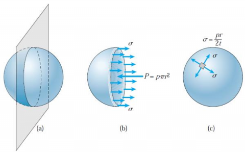
Figure 2. Tensile stresses σ in a spherical pressure vessel [11]
A more general approach at finding the Tensile Stress σ is by cutting the sphere into two hemispheres [10, 11] as shown in Figure 2 which can be used to show that
$\sigma=\frac{P r}{2 t}$ (1)
where σ represents the tensile stresses in the wall of the vessel, the fluid pressure is p and t is the wall thickness
Any section that passes through the center of the sphere yields the same result.
3.2 Sections development
Mathematical modeling of spherical tank as previously developed was derived based on the structure and the output transfer function where the spherical tank system was identified as a nonlinear complex structure [12]. The framework developed in this work is however simplified and has been successfully used to develop some prototypes. Another previous Mathematical model of spherical screw lines developed also involved the use of relatively complex single-blade helicoid equation together with the equation of a curve of crossing of surfaces of the sphere and helicoid [13, 14].
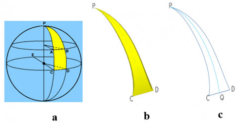
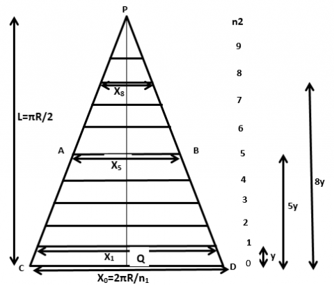
In this work however, the approach employed in developing the spherical tank involved dividing the sphere into two hemispheres and subsequent division of each of the hemispheres into sections. The material used is mild steel and a simplified procedure was established for the section/profile development and the number of sections needed to obtain a near-perfect spherical shape established. Each of the sections developed is as represented by the profile PCD in Figures 3 and 4.
The procedure for the sectional development (Figures 3 and 4) involves the following
$X_{0}=^{2 \pi R} / n_{1}$ (2)
Figure 3. Sectional development
Figure 4. Hemisphere used for mathematical analysis
Figure 5. Sectional divisions along minor circles
Figure 6. Major circle sectional analysis
Figure 7. First minor circle sectional analysis
Figure 8. Fifth minor circle sectional analysis
Figure 9. n2th minor circle sectional analysis
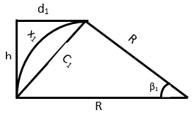
From Figure 6 and using the Cosine Rule for the cord length C0 is
$C_{0}^{2}=R^{2}+R^{2}-2 . R . R \cos \alpha$
$C_{0}=\sqrt{2 R^{2}(1-\cos \alpha)}$
$C_{0}=\sqrt{2 R^{2}(1-\operatorname{Cos}(360 / n 1))}$ (3)
Length of the arc CD from Figures 5 and 6 is
$x_{0}=\frac{2 \pi R}{n 1}=\frac{\alpha}{360} 2 \pi R$ (4)
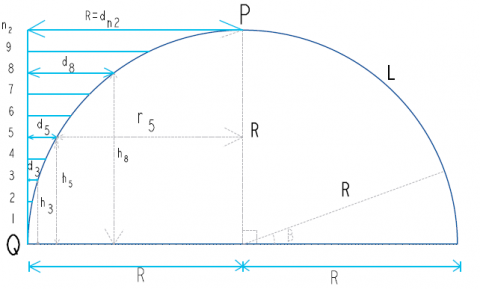
Using Figures 7 to 9;
From the Cosine Rule, Cord length C1 corresponding to arc length x1 is
$C_{1}^{2}=R^{2}+R^{2}-2 . R . R \operatorname{Cos} \beta_{1}$
$C_{1}=\sqrt{2 R^{2}\left(1-\operatorname{Cos} \beta_{1}\right)}$ (5)
where β1=90/n2 (see Figure 4)
From Figure 7, using Pythagoras theorem and taking h1 = h = R/n2; $d_{1}=\sqrt{C_{1}^{2}-h^{2}}$; $r_{1}=R-d_{1}$ (see Figure 8).
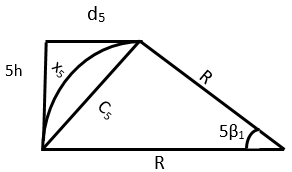
Similarly from Figure 8,
$C_{5}=\sqrt{2 R^{2}\left(1-\cos \beta_{5}\right)}$
where $\beta_{5}=5 \beta_{1}=5 * 90 / n_{2}$ and $d_{5}=\sqrt{C_{5}^{2}-h_{5}^{2}}=\sqrt{C_{5}^{2}-(5 h)^{2}}$; $r_{5}=R-d_{5}$
For n2 number of divisions which is equivalent to the number of minor circles obtained for each of the two hemispheres of the spherical shape of interest,
$\begin{aligned} d_{n 2}=\sqrt{C_{n 2}^{2}-h_{n 2}^{2}} &=\sqrt{C_{n 2}^{2}-\left(n_{2} . h\right)^{2}} \\ r_{n 2} &=R-d_{n 2}=R-R=0 \end{aligned}$ (6)
since $d_{n 2}=R$ (7)
Eq. (7) implies that there is no minor circle at the tip of the sphere.
With reference to Eq. (6);
Since $d_{n 2}=R$; together with n2 and h are known
Eq. (6) becomes
$R=\sqrt{C_{n 2}^{2}-\left(n_{2} \cdot h\right)^{2}} \quad$ or
At $x_{o}=\frac{2 \pi R}{n 1} ; \mathrm{d}_{\mathrm{o}}=0 ; \mathrm{h}_{\mathrm{o}}=0$
For our spherical shape to be well formed, the cord length C0 must be approximately equal to the arc length x0.
Using Eqns. (3) and (4) and tabulating Cord Length C0 and Arc Length L for different values of n1 results in Table 1. The higher the number of sections n1 used, the closer is the value of C0 to L
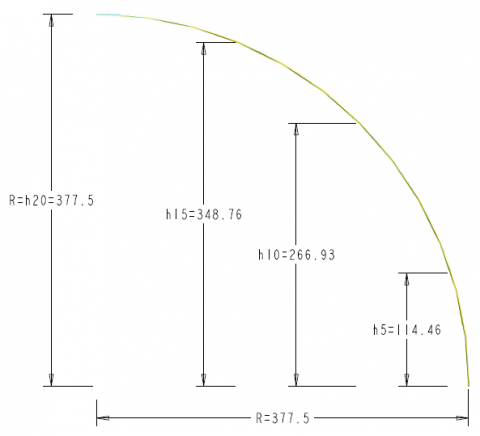
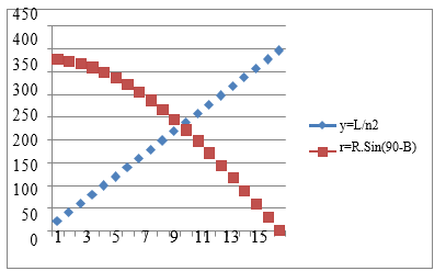
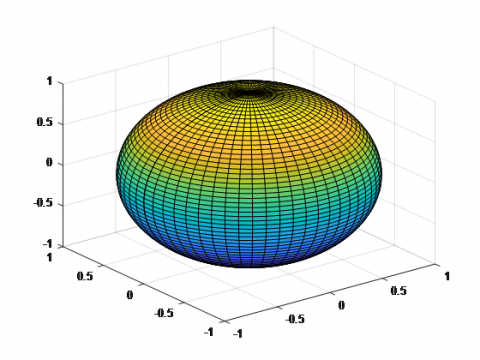
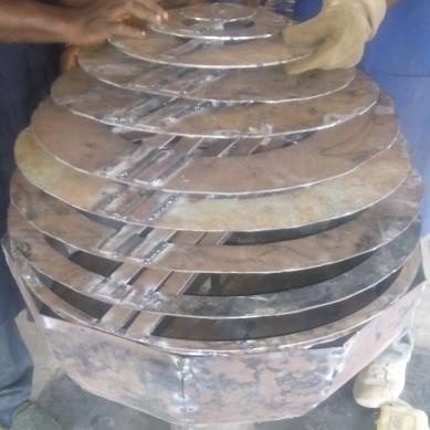
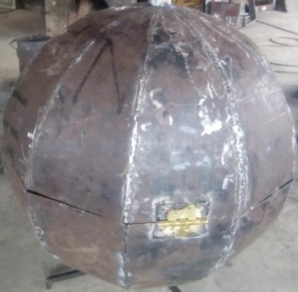
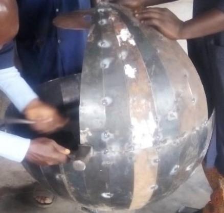
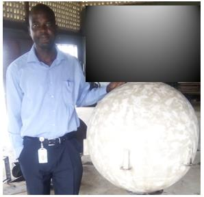
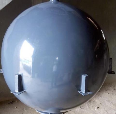
A more comprehensive analysis and comparisons of the generated data from the developed Mathematical models are as shown in Table 2. Figure 10 shows some of the points of reference on the developed section of the sphere as previously depicted in Figure 3 while Figure 11 shows the variation of the linearized sectional height to the actual equivalent sectorial arc length. Figures 12 and 13 illustrate the level of sphericalness achieved by using different number of sections, that is, n1=10 and n1=30 for spherical shapes formation which is equivalent to n1=20 and 60 respectively for the corresponding hemispherical shapes. The developed spherical tanks at different levels of welding/fabrication are as shown in Figure 14 to 20.
Table 1. Table of values of C0 approaching L as n1 increases
|
R |
n1 |
A=360/n1 |
C0=sqrt((2*R^2)-2*R*R*cosd(A)) |
L=(A*PI*R)/180 |
L-C0 |
|
377.5 |
5 |
72.000 |
443.778 |
474.380 |
30.603 |
|
10 |
36.000 |
233.308 |
237.190 |
3.882 |
|
|
15 |
24.000 |
156.973 |
158.127 |
1.154 |
|
|
20 |
18.000 |
118.108 |
118.595 |
0.487 |
|
|
25 |
14.400 |
94.627 |
94.876 |
0.250 |
|
|
30 |
12.000 |
78.919 |
79.063 |
0.144 |
|
|
35 |
10.286 |
67.678 |
67.769 |
0.091 |
|
|
40 |
9.000 |
59.237 |
59.298 |
0.061 |
|
|
45 |
8.000 |
52.666 |
52.709 |
0.043 |
|
|
50 |
7.200 |
47.407 |
47.438 |
0.031 |
|
|
55 |
6.545 |
43.102 |
43.125 |
0.023 |
|
|
60 |
6.000 |
39.514 |
39.532 |
0.018 |
|
n1 = |
|
|
n2= |
20.00 |
R= |
377.50 |
B= |
90.00 |
|
x0=2.PI*R/n1 |
|
n1(th) |
n2 |
n2(th) |
R |
L |
y=L/n2 |
B=90/n2 |
h =R.Cos(90- B) |
r =R.Sin(90- B) |
x =2.PI.r/n1 |
|
|
1 |
20 |
1 |
377.50 |
592.98 |
19.77 |
4.50 |
29.62 |
376.34 |
78.82 |
1.00 |
|
2 |
20 |
2 |
377.50 |
592.98 |
39.53 |
9.00 |
59.05 |
372.85 |
78.09 |
2.00 |
|
3 |
20 |
3 |
377.50 |
592.98 |
59.30 |
13.50 |
88.13 |
367.07 |
76.88 |
3.00 |
|
4 |
20 |
4 |
377.50 |
592.98 |
79.06 |
18.00 |
116.65 |
359.02 |
75.19 |
4.00 |
|
5 |
20 |
5 |
377.50 |
592.98 |
98.83 |
22.50 |
144.46 |
348.76 |
73.05 |
5.00 |
|
6 |
20 |
6 |
377.50 |
592.98 |
118.60 |
27.00 |
171.38 |
336.35 |
70.45 |
6.00 |
|
7 |
20 |
7 |
377.50 |
592.98 |
138.36 |
31.50 |
197.24 |
321.87 |
67.41 |
7.00 |
|
8 |
20 |
8 |
377.50 |
592.98 |
158.13 |
36.00 |
221.89 |
305.40 |
63.96 |
8.00 |
|
9 |
20 |
9 |
377.50 |
592.98 |
177.89 |
40.50 |
245.17 |
287.05 |
60.12 |
9.00 |
|
10 |
20 |
10 |
377.50 |
592.98 |
197.66 |
45.00 |
266.93 |
266.93 |
55.91 |
10.00 |
|
11 |
20 |
11 |
377.50 |
592.98 |
217.42 |
49.50 |
287.05 |
245.17 |
51.35 |
11.00 |
|
12 |
20 |
12 |
377.50 |
592.98 |
237.19 |
54.00 |
305.40 |
221.89 |
46.47 |
12.00 |
|
13 |
20 |
13 |
377.50 |
592.98 |
256.96 |
58.50 |
321.87 |
197.24 |
41.31 |
13.00 |
|
14 |
20 |
14 |
377.50 |
592.98 |
276.72 |
63.00 |
336.35 |
171.38 |
35.89 |
14.00 |
|
15 |
20 |
15 |
377.50 |
592.98 |
296.49 |
67.50 |
348.76 |
144.46 |
30.26 |
15.00 |
|
16 |
20 |
16 |
377.50 |
592.98 |
316.25 |
72.00 |
359.02 |
116.65 |
24.43 |
16.00 |
|
17 |
20 |
17 |
377.50 |
592.98 |
336.02 |
76.50 |
367.07 |
88.13 |
18.46 |
17.00 |
|
18 |
20 |
18 |
377.50 |
592.98 |
355.79 |
81.00 |
372.85 |
59.05 |
12.37 |
18.00 |
|
19 |
20 |
19 |
377.50 |
592.98 |
375.55 |
85.50 |
376.34 |
29.62 |
6.20 |
19.00 |
|
20 |
20 |
20 |
377.50 |
592.98 |
395.32 |
90.00 |
377.50 |
1.00 |
0.21 |
20.00 |
Figure 10. Points of reference on the developed section of the sphere
Figure 11. Variation of the linearized sectional height to the actual equivalent sectorial arc length
Figure 12. Sphericalness achieved with n1=10
Figure 13. Sphericalness achieved with n1=30
Figure 14. First section being welded to the upper hemisphere
Figure 15. 10 section-sphere under development with lower hemisphere
Figure 16. Developed sphere of 10 sections
Figure 17. 30-Section 225 liter capacity spherical tank under development
Figure 18. Complete 30-Section 225liter capacity spherical tank developed
Figure 19. Body-filed 30-Section 225liter capacity spherical tank developed
Figure 20. Grey-Coated 30-Section 225liter capacity spherical tank developed
This paper has developed mathematical and procedural frameworks that will facilitate the development of spherical storage tanks. The effect of the number constituent sections on the sphericalness obtainable was also illustrated by developing a 225-litre capacity spherical storage tank using ten and twenty sections respectively. It is hoped that the framework developed will encourage the development and usage of spherical tanks when they are needed and not approximate them to cylindrical tanks with hemispherical caps.
The authors acknowledge with gratitude, the efforts of the Engineering Personnel of the Design, Modeling and Simulation Department as well as the Technical Staff of the Manufacturing Department of the Engineering Materials Development Institute Akure Nigeria for the valuable roles they played in fabricating the spherical tank.
|
τrυ, τυr, τrθ, τθr, τθυ, τυθ |
Shear Stresses in different planes in N/m2 |
|
|
σrr |
Normal Stress in N/m2 |
|
|
n1 |
Number of Sections |
|
|
n2 |
Number of Minor Circles |
|
|
X0 |
Equivalent base (arc) length of each section of the sphere in mm |
|
|
R |
Great Circle Radius in mm |
|
|
α |
Angle substended by an arc of the section in degrees |
|
|
L |
Length of an Arc of a constituent great circle |
|
|
C0, Cn |
Equivalent Chord Length in mm |
|
|
β |
Angle substended by a minor arc |
|
[1] Paliwal, D.N. (1988). Design of steel storage tanks with spherical bottoms. International Journal of Pressure Vessels & Piping, 35(5): 383-401. http://dx.doi.org/10.1016/0308-0161(88)90134-2
[2] Shin, S.H., Ko, D.E. (2016). A study on forces generated on spherical type LNG tank with central cylindrical part under various static loading. International Journal of Naval Architecture and Ocean Engineering, 8(6): 530-536. http://dx.doi.org/10.1016/j.ijnaoe.2016.07.001
[3] Hutchinson, J.W. (2016). Buckling of spherical shells revisited. Proc. R. Soc. A, 472(2195): 1-25. https://doi.org/10.1098/rspa.2016.0577
[4] Afkar, A., Camari, M.N., Paykani, A. (2014). Design and analysis of a spherical pressure vessel using finite element method. World Journal of Modelling and Simulation, 10(2): 126-135.
[5] Zhang, S.H., Wang, B.L., Shang, Y.L., Kong, X.R., Hu, J.D., Wang, Z.R. (1994). Three-dimensional finite element simulation of the integral hydrobulge forming of a spherical LPG tank. International Journal of Pressure Vessels & Piping, 65: 47-52. http://dx.doi.org/10.1016/0308-0161(94)00158-F
[6] Sivy, M., Musil, M. (2018), Design of the spherical liquid storage tanks for earthquake resistance. ANNALS of Faculty Engineering Hunedoara – International Journal of Engineering Tome XVI.
[7] Lee, H.S., Yoon, J.H., Park, J.S., Yi, Y.M. (2005). A study on failure characteristic of spherical pressure vessel. Journal of Materials Processing Technology, 164-165: 882-888. https://doi.org/10.1016/j.jmatprotec.2005.02.208
[8] Baaji, B., Saraswathamma, K., Madabhushi, R., Sutar, S. (2016). Design and analysis of spherical pressure vessels with pressure and thermal effects. International Journal of Mechanical Engineering and Automation, 3(6): 239-248.
[9] Roylance, D. (2001). Pressure Vessel. A Monograph in the Department of Materials Science and Engineering Massachusetts Institute of Technology Cambridge, MA 02139.
[10] Mercy, D., Girirajkumar, S.M. (2017). Modeling and analysis of a real time spherical tank process for sewage treatment plant. International Journal of Applied Mathematics & Information Sciences, 11(5): 1491-1498. http://dx.doi.org/10.18576/amis/110528
[11] Gere, J.M. (2004). Mechanics of materials. 6th Edition, Thomson Learning, Inc. http://dx.doi.org/10.1007/978-1-4899-3124-5
[12] Avinashe, K.K., Mathews, M. (2015). Internal model control design for nonlinear spherical tank level process. IJETSR, 2(8): 12-18.
[13] Krishnapriya, K., Devi, M.R., Roshini, U., Jayachitra, A. (2017). Analyzing the performance of interacting spherical tank system using internal model controller (IMC) and Metaheurstic algorithm. International Journal of Advanced Research in Computer and Communication Engineering, 6(4): 36–42.
[14] Yuan, S.J., Wang, F.Z., Wang, Z.R. (1997). Safety analysis of 200 m3 LPG spherical tank manufactured by the dieless hydro-bulging technology. Journal of Materials Processing Technology, 70: 115-219. http://dx.doi.org/10.1016/S0924-0136(97)02920-8
[15] Bharathi, M., Selvakumar, C., Kalpana, A. (2014). Model based controller design for a spherical tank. IOSR Journal of Electrical and Electronics Engineering (IOSR-JEEE), 9(2): 74-79. http://dx.doi.org/10.9790/1676-09267479
[16] Muthumari, S., Rakesh Kumar, S. (2017). Design of robust controller for hemi-spherical tank system using volumetric observer. International Journal of Applied Engineering Research, 12(17): 6477-6481.