Charef Khoudja Nabila* | Soudani Azzedine
OPEN ACCESS
The purpose objective of this study is to examine numerically the effects of surface roughness on laminar water flow behavior in a three-dimensional microchannels with sinusoidal surface roughness. The considered geometry is a rectangular channel of length L=152.4 mm, width a=12.7 mm, and height b varying from 100 µm to 750 µm. The surface roughness is one of the problems in micro-channels, as it increases the friction at the wall for this reasona simulation model was established using the commercial CFD software. The results indicate that a very good agreement between classical theory and the numerical model for smooth channels, but the results concerning the influence of roughness show that roughness have a marked effect at the microscale flow field.
CFD, friction factor, laminar flow, rough surface, smooth surface
Microscale phenomena is very important for designing efficient microdevices and to explore the fundamental physical mechanisms of fluid flow and heat transfer in micro-channels, which leads to the study of many effects, including the size effect, surface roughness, viscous effect, effect of electrostatic force, axial thermal conduction in the channel wall, surface geometry, measurement errors, etc. [1]. A microscale encounters an obstacle on fluid behavior in microchannels as compared to conventional sized channels. Actually, as mentioned in the abstract section, it will be rather easy to follow these rules as long as you just replace the “content” here without modifying the “form”.
Given the importance and complexity of micrometric phenomena, a lot of work has been done in this field to characterize the pressure drop of water flows in smooth and rough microchannels.
At the smooth microchannels, the macroscopic models of the fluids Mechanics are always valid in the smooth micro-conduits which is proved by most studies, such us: Li [1]; Flockhart [2]; Yang [3]; Gao [4];Bavière [5]; Srivastava [6]; Brackbil [7] ; Dharaiya [8, 9]. Additionally, we also performed a two-dimensional numerical study on the hydrodynamic behavior of the water flowing through a smooth rectangular microchannel from 0.1 mm to 1 mm in height Charef-Khodja [10]. The Reynolds numbers were between 50 and 10000. The simulation was carried out using the Fluent CFD which is based on the Finite Volume Method. The simulation results obtained are in good agreement with the experimental results obtained by Gao [4] and with the conventional theory.
At the rough microchannels, research on the effect of roughness in the smallest conduct has a strong interest in recent years. According to Bavière [5], the roughness is potentially interesting for industrial applications to intensify heat exchange. It is therefore important to understand the effect of roughness on a micro-flow and to characterize its influence on pressure drops. Among the works published were done to describe the rough microchannels, for example Li [2] have experimentally studied the laminar flow with deionized water flowing in rough microtubes of stainless steel. The Reynolds number ranged from 20 to 2400 and the hydraulic diameter is from 373 to 1570 μm. The relative roughness is 2.4 %, 1.4 %, 0.95 %. The friction factors agree well with the conventional theory prediction for a relative roughness less than 1.5%, and increases as the surface relative roughness increases.
Bavière [5] performed experimental study to characterize the friction on water flow in rough micro-channels of rectangular section. The heights explored are 296 μm, 196 μm, and 96 μm. It found that the Poiseuille number increases as the relative roughness increases.
Srivastava [6] arrived at an understanding of the fundamental effects of roughness in rectangular channels in the micrometer scale. Where, they performed a three-dimensional numerical simulation of laminar flow and incompressible fluid using CFD software, FLUENT. Two roughness geometries (λ=508 µm and λ=1,016 µm) with Dh ranging from 586 μm to 961 μm. They found a good agreement with published experimental results.
Brackbil [7] have experimentally examined the effects of different roughness structures (uniform roughness, sawtooth roughness) on laminar flow through rectangular microchannels of high aspect ratio. The relative roughness which varies between 1.4 % and 27.6 % with pitches varying from 503 to 2015 µm. Deionized water is used as a working fluid. They see that as the pitch of the elements increases, the experimental results deviated from the theory.
A three-dimensional numerical study of incompressible laminar fluid flow in mini-channels and microchannels was performed by Dharaiya [8, 9] to analyze the effects of structured sinusoidal roughness elements on fluid flow. The numerical simulation for two different roughness geometries (λ=150 µm and 250 µm) showed very good agreement with experiments.
A three-dimensional numerical simulation of serpentine micro-channels with designed roughness in form of obstructions placed along the channels walls was presented by Rawool [11] to study the effect of various parameters such obstruction height and geometry on the friction factor. They found that the friction factor increases with the increase in obstruction height. It is also higher for rectangular and triangular obstructions, it decreases as the obstruction geometry is changed to trapezoidal.
Croce [12] also performed three-dimensional numerical computations to study the effects of surface roughness on pressure drop in micro-channel flows in three-dimensional conical peaks distributed on the ideal smooth surfaces of a plane microchannel. The results showed a remarkable effect of roughness on pressure drop.
Ghajar et al. [13] studied experimentally the effect of roughness on the friction factor for the single-phase flow characteristics of distilled water in stainless-steel mini- and microtubes of diameters ranging from 2083 to 337 µm. The results showed that in laminar regime, the friction factor increases with increasing roughness parameter.
Liu [14] conducted an experimental study on the flow behavior in micro-channels with three different relative roughness (0.58 %, 0.82 %, 1.26 %). The experiments were performed for a range of Reynolds numbers (Re=200-2100) and the air was used as the working fluid. The results show that the friction factor increases with increasing relative surface roughness.
Kharati-Koopaee [15] performed a three-dimensional numerical simulation to characterize the pressure drop in rectangular micro-channels consisting of surfaces with structured sinusoidal roughness elements. Air and water are chosen as the working fluids. Two roughness patterns were used aligned and offset with changing parameters such as roughness height (10-100 μm), pitch (150-350 μm), and channel height (250-550 μm). The friction factor obtained is in good agreement with the theoretical approach.
Recently, Siddharth [16] analyzed numerically the fluid flow through microchannels with structured sinusoidal roughness in aligned and offset pattern at various Reynolds number ranging from 100 to 500. The validation of numerical model for friction factor is in good accord with the theoretical and the results of Koopaee and Zare [15]. The results found that offset pattern has higher pressure drop and friction factor compared to the aligned roughness pattern.
Lalegani [17] performed a two-dimensional numerical simulation to analyze the effects of roughness elements on the fluid flow in the microchannels. They have considered various types of roughness on the microchannel wall such as rectangular, trapezoidal, elliptical, triangular and complex. The values of relative roughness are from 2.5 to 15 %. The numerical results found that friction factor and pressure drop in rectangular roughness state are bigger than in other states, and triangular roughness causes the least pressure drop and friction factor than other roughness elements.
According to the literature, most studies concerning the structure roughness instead of the random roughness as this type (structured) is easy to create and model numerically. Among the authors who focused on this type of roughness we can mention Dharaiya [8, 9], Kharati-Koopaee [15], and Siddharth et al. [25]. So, we will also consider a structured sinusoidal roughness in a three-dimensional microchannels on the pressure drop and the friction factor. For this purpose, we will design numerically (using the Fluent commercial software; version 6.3) the geometry of the test section used in the experiments conducted by Wagner [18, 19].
The remainder of this paper is organized as follows: Section 2 describes the geometry of this work, Section 3 introduces the equations governing the problem, Section 4 summarizes the different steps to control the numerical model, Section 5 presents results and their discussion for two parts: a validation of numerical model with experimental results from the literature, and a comparison the results presented between the smooth and rough microchannels, finally Section 6 concludes most of the results and future perspectives In this field.
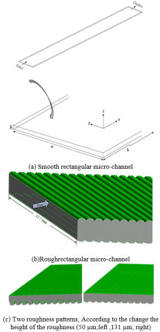
The geometry studied in this work is a rectangular micro-channel of length L=152.4 mm, width a=12.7 mm and a height b which can be adjusted between 100 μm and 755 μm (Figure 1). Two configurations have been studied: a smooth channel (Figure 1.a) and a rough channel (Figure 1.b). Their dimensions are those defined by the experimental data of Wagner [18, 19].
In the case of the smooth channel all the walls (upper, lower, and lateral) are considered smooth. While, the second configuration (rough) has a sinusoidal roughness on both the bottom and the top wallsshown on Figure 2. The other boundaries of the channel are defined as smooth walls.
Figure 1. Geometries of the micro-channels considered
2.1 Form of roughness
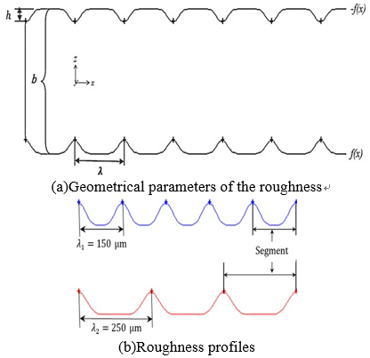
The roughness takes the sinusoidal form in the x-direction and can be expressed by:
$f(x)=h \cos ^{p}\left(\frac{\pi}{\lambda} x\right) \frac{b}{2}$ (1)
where p is the cosine power it's a positive even number for controls the slope of the peaks, λ is the roughness pitch, a roughness height h, and a is a height of the canal (Figure 2.a). In the Figure 2.b, a graphic illustration of roughness profiles according to the change of pitch $\lambda\left(\lambda_{1}=150 \mu \mathrm{m} \text { and } \lambda_{2}=250 \mu \mathrm{m}\right)$ .
Each channel wall consists of segments:
For $\lambda_{1}=150 \mu \mathrm{m}$ with 1016 segments.
For $\lambda_{2}=250 \mu \mathrm{m}$ with 610 segments.
Figure 2. Representative scheme of the sinusoidal roughness
Table 1 contains the values of the different geometrical parameters used in the present work. These dimensions are those defined by the experimental data of Wagner et al. [18]
Table 1. Values of the different geometrical parameters
|
Channel height, b(µm) |
Roughness height, h(µm) |
Roughness pitch, λ (µm) |
|
550 |
50 |
150 |
|
550 |
50 |
250 |
|
755 |
131 |
250 |
|
755 |
150 |
250 |
3.1 Equations governing the problem
Consider that the flow is stationary, laminar,incompressible, viscous, and without heat transfer. The fluid used for the simulations is a Newtonian liquid (water). Thus, the basic equations governing the flow are given by Yunus et al. [20]:
- Equation of Continuity
$\nabla \vec{v}=0$ (2)
- Equation of Momentum
$\rho(\vec{v} \cdot \nabla \vec{v})=-\nabla p+\mu \nabla^{2} \vec{v}$ (3)
3.2 Friction factor in classical theory
According to Shah and London [21], the friction factor of the laminar flow in smooth ducts can be determined by the following relation:
$f=\frac{\tau_{p}}{\frac{1}{2} \rho u_{a v g}^{2}}$ (4)
where $\tau_{p}$ and $u_{a v g}$ are respectively, the parietal shear stress and the average fluid velocity in the duct.
The pressure drop $\Delta p$ for a length L of the channel is written classically by the Eq. (5):
$\Delta p=f \frac{L}{D_{h}} 2 \rho u_{a v g}^{2}$ (5)
with, the hydraulic diameter of the duct $D_{h}$ is calculated simply by the Eq. (6):
$D_{h}=\frac{4 * \text { Area }}{\text { Perimeter }}=\frac{4 a b}{2(a+b)}$ (6)
For laminar flows in rectangular channels, the theoretical friction factor is predicted by Kakac [22] as defined in Eq. (7).
$\begin{aligned} f_{\text {theo}}=\frac{24}{R e}\left(1-1.3553 \alpha+1.9467 \alpha^{2}-1.7012 \alpha^{3}+\right.& \\ 0.9564 \alpha^{4}-0.2537 \alpha^{5} ) & \end{aligned}$ (7)
The Eq. (8) was further used to define the aspect ratio as indicated below:
$\alpha=\frac{a}{b}$ (8)
$R e=\frac{\rho D_{h} u_{a v g}}{\mu}$ (9)
or, Re denotes the Reynolds number based on the hydraulic diameter of the channel.
3.3 Number of poiseuille
For fully developed laminar flow in a conventionally sized channel, the Poiseuille Number according to Shah and London [21] is determined by the following relationship:
$P o=f_{\text {theo}} R e$ (10)
A water flow in a micro-channel is performed numerically using Fluent (CFD; Computation Fluid Dynamics) which is based on the finite volume method. The Simple algorithm was used for pressure-velocity coupling, a second-order upwind scheme was used for the discretization of the smooth case and a first-order upwind scheme was employed for rough case. The convergence criterion for all residues is 10-6.
4.1 Mesh
The most critical part of the CFD process is the mesh of the model. The three-dimensional geometry (Figure1) have been realized using the gambit mesher, which uses for geometry and grid generation of the computational domain. Both configurations of the micro-channel (smooth and rough) have been meshed with a structured hexahedral grid shown in the figure below (Figure 3).
We see in Figure 1.b, the possibility of studying symmetry, in particular with regard to rough channels for their difficulty for this, we preferred to work with moiety of the domain of study (the symmetry with respect to median plane normal to direction z) (Figure 1. c), in order to reduce the number of mesh elements and to save computing time. But even so, to generate a single mesh it takes more than 24 hours with an Intel Core i7 processor.
Figure 3. A structured hexahedral mesh of a part of the microchannel
4.2 Boundary conditions
The equation system governing the problem must be accomplished by boundary conditions for its resolution. So, our boundary conditions are set as follows: At the input (velocity-inlet) the velocity distribution is supposed to be uniform and calculated from the Reynolds number varying from 20 to 1400. At the output, the pressure condition (pressure-outlet) is applied, the other boundaries of the domain are defined as solid walls.
4.3 Grid dependency
In this study, we used three grids (coarse, medium, and fine) to study mesh independence. For this, the friction factor has been considered as an important criterion to ensure that the results are independent of the mesh. We apply this analysis on both micro-channels (smooth, rough). According to Roache [23], the relative error due to the mesh (ϵ) was estimated by the following formula.
$\epsilon(\%)=\left|\frac{e_{r 2}-e_{r 1}}{e_{r 1}}\right| \times 100$ (11)
or, er is the relative error between the two grid solutions; er1 (fine grid) et er2 (coarse grid).
Here, we took (Re=800 and $b=378 \mu m$ ) for the smooth channel and (Re = 800, b = 550 µm, ε =50 µm, and λ=250 µm) for the case of the rough channel. It is observed that the friction factor changed by 1.47 % (smooth channel), 7.89 % (rough channel) from the first to the second mesh, and only by 0.37 % (smooth channel), 6.86 % (rough channel) after further refinement of the mesh (see Table 2). Therefore, the intermediate mesh has been chosen.
Table 2. Estimation of the relative error of the friction factor
|
|
Mesh elelements |
Grid system |
Friction factor $\left(f_{\text { presentstudy }}\right)$ |
$\epsilon(\%)$ |
|
Smoothchannel |
907200 |
1-2 |
0.0288 |
1.47 |
|
1979040 |
2-3 |
0.0292 |
0.37 |
|
|
2979420 |
1-3 |
0.0294 |
1.84 |
|
|
Rough channel |
2130120 (sym) |
1-2 |
0.0443 |
7.89 |
|
3108560 (sym) |
2-3 |
0.0410 |
6.86 |
|
|
3943040 (sym) |
1-3 |
0.0384 |
15.29 |
5.1 Validation of the numerical model
5.1.1 Smooth channel
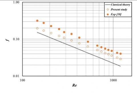
Figure 4. Validation of the present friction factor with experimental results and conventional theory for a smooth microchannel
A numerical simulation of the water flow characteristics in smooth microchannels can be validated with the data of Wagner [18] and the classical theory. Friction factor is the parameter test of validation, it has been plotted as a function of Reynolds for the three studies (Figure 4). Those friction factors were calculated according to: (friction factor)numby Eq (4), (friction factor)exp by Eq. (5), and(friction factor)theoby Eq (7); with α=0.6. It can be seen that computed friction factor agreed well with those measured in the experiments and the classical theory. As well, the Table 3 shows a comparison between the present values of friction factor and the data available in literature, there is a very good agreement was observed.
Table 3. Comparison of friction factors for different work
|
b (µm) |
Re |
$f_{\text { theo }}$ |
$f_{\exp }[19]$ |
$f_{\mathrm{num}}[9]$ |
$f_{\text { Present study }}$ |
|
102 378 548 751 |
784 800 784 785 |
0.0303 0.0288 0.0289 0.0283 |
0.0232 0.0331 0.0330 0.0299 |
0.0238 0.0336 0.0332 0.0304 |
0.0297 0.0288 0.0292 0.0290 |
|
Re |
Error $\%$ |
Error $\%$ |
|
784 800 784 785 |
2.58 1.51 0.76 1.67 |
1.91 0.10 1.01 2.36 |
5.1.2 Rough channel
In Figure 5, we present a validation of present numerical study of fluid flow in rough microchannels with the experimental results and the classical theory. It can see an agreement between the three studies, there is a slight deviation and this is due to the effect of the roughness element height used in this case h=131 µm.
Figure 5. Validation of the present friction factor with experimental results and conventional theory for a rough microchannel; h=131 µm, λ=250 µm, and b=755 µm
5.2 Effects of roughness elements on pressure drop
5.2.1 Roughness height
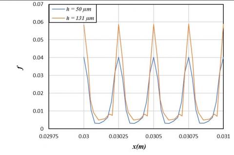
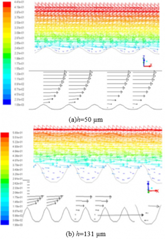
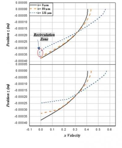
Figure6shows the variation of local friction factor with horizontal position of the channel (x=30 - 31.25 mm) in the rough microchannel of 755 μm height and for Re=422. Two different roughness height are considered as h1= 50 µm and h2= 131 µm. It can be observed that the local friction factor for h1= 50 µm is inferior compared to the roughness height h2= 131 µm, this means that the local friction factor depends on the roughness height. Evidently, the local friction factor increases with increasing roughness height h2= 131 µm caused by decrease of the flow passage section and creating a recirculation zone near the microchannel wall. We note well on the Figure 7 that the normalized Poiseuille number is also increases with increasing roughness height.
Figure 6. Variation of local friction factor with horizontal position x estimated by 1.25 mm
Figure 7. Variation of normalized Poiseuillenumberversus Reynolds number
The velocity vectors are presented in Figure 8 for two different roughness height (h=50,131 µm) at the xz plane. It can be seen that the velocity vectors follow the direction of the flow in the case h=50 μm, but there are recirculationzones near the microchannel wall (Figure 8 b)these zones created because the roughness height is greater compared to the first case.The roughness height has effects on the velocity vectors. In addition, it is clear that the velocity profile takes a parabolic form of Poiseuille Figure 8. aon the right. Same notes show in the Figure 9.
Figure 8. Velocity vectors of the flow in x–z planefor a height channel b=755 µm, λ=250 µm, and Re=422
Figure 9. Horizontal velocity profiles for a height channel b=755 µm, λ=250 µm, and Re=422
Up; x= 80,125 mm, Below; x= 80 mm
5.2.2 Roughness pitch
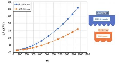
Figure 10.Variation of pressure drop with Reynolds number for a height channel b=550 µm, h=50 µm, and Re=422
Figure 10 shows the variation of pressure drop with Reynolds number for roughness pitch values of $\lambda_{1}=150 \mu \mathrm{m}$ and $\lambda_{2}=250 \mu \mathrm{m}$. The influence of the variation of the roughness pitch on the pressure drop is clearly observed. Therefore, the increase in roughness pitch causes to a decrease in pressure drop ( $\lambda_{1}=150 \mu \mathrm{m} \rightarrow$ 0.6 - 60 KPa, $\lambda_{2}=250 \mu \mathrm{m} \rightarrow$ 0.4 - 30 KPa) this is due to a decrease in the number of flow areas in the channel.
5.3 Effect of channel height on Poiseuille number
Figure11 shows the variation of Poiseuille number ( $P o=f_{\text {simulated}} R e$ ) with Reynolds number for different channel heights. The roughness height and the roughness pitch are given, respectively50 μm and 250 μm. The values of Poiseuille number decrease with the increase of channel height, due to increasing of the flow passage section and rough elements are inactive in this case. These results are agreeing with the conventional theory presented by Shah and London [21].
Figure 11. Effect of channel height on Poiseuille number
The effect of sinusoidal surface roughness in a three-dimensional rectangular microchannel on laminar liquid flow pressure drop was carried numerically using computational fluid dynamics (CFD). Three different geometries were generated, one smooth and two rough motifs by changing the roughness height (50,130 μm), roughness pitch (150,250 μm) and channel height (550,750 μm).
From the results obtained, the main conclusions are as follows:
The results of the study indicate that the wall roughness causes more impacts on the flow in microchannels than in conventional channels,this means that the problem of roughness has not been solved permanently.
One may also wonder about the effects of roughness induced in thermal behavior,this point will deal in future research.
|
A |
Area, m2 |
|
a b Dh f h L p P Po Re u; v |
Channel width, m Channel height, m Hydraulic diameter, m Friction factor Height of the roughness element, m Length, m Pressure, Pa Perimeter, m Poiseuille number Reynolds number Velocity, m.s-1 |
|
Greek symbols |
|
|
α |
Aspect ratio |
|
λ r ϵ µ |
Roughness pitch, m Density, kg.m-3 Relative error Dynamic viscosity, kg.m-1.s-1 |
|
Subscripts |
|
|
sym |
Symmetrical |
|
exp theo num avg |
Experimental value Theoretical value Numerical value Average value |
|
x |
x-direction |
|
y |
y-direction |
|
z |
z-direction |
[1] Li Z, He YL, Tang GH, Tao WQ. (2007). Experimental and numerical studies of liquid flow and heat transfer in microtubes. International Journal of Heat and Mass Transfer 50(17-18): 3447-3460. https://doi.org/10.1016/j.ijheatmasstransfer.2007.01.016
[2] Flockhart SM, Dhariwal RS. (1998). Experimental and numerical investigation into the flow characteristics of channels etched in <100> silicon. Journal of Fluids Engineering 120(2): 291-295. https://doi.org/10.1115/1.2820647
[3] Yang CY, Wu JC, Chien HT, Lu SR. (2003). Friction characteristics of water, R-134a and air in small tubes. Microscale Thermophysical Engineering 7(4): 335-348. https://doi.org/10.1080/10893950390243608
[4] Gao P, Le Person S, Favre-Marinet M. (2002). Scale effects on hydrodynamics and heat transfer in two-dimensional mini and microchannels. International Journal of Thermal Sciences 41(11): 1017-1027. https://doi.org/10.1016/s1290-0729(02)01389-3
[5] Bavière R. (2005). Etude de l’hydrodynamique et des transferts de chaleur dans des microcanaux. Thesis, Univ. Joseph - Fourier - Grenoble I.
[6] Srivastava RR, Schneider NM, Kandlikar SG. (2009). Numerical simulation of single-phase liquid flow in narrow rectangular channels with structured roughness walls. In Proceedings of the Seventh International ASME Conference on Nanochannels, Microchannels and Minichannels.ICNMM2009-82255, Pohang, South Kore. https://doi.org/10.1115/icnmm2009-82255
[7] Brackbill TP, Kandlika SG. (2010). Application of lubrication theory and study of roughness pitch during laminar, transition, and low reynolds number turbulent flow at microscale. Heat Transfer Engineering 31(8): 635-645. https://doi.org/10.1080/01457630903466621
[8] Dharaiya VV, Kandlikar SG. (2011). A numerical study to predict the effects of structured roughness elements on pressure drop and heat transfer enhancement in minichannels and microchannels. Proceedings of the ASME 2011 International Mechanical Engineering Congress & Exposition, IMECE2011-65262, Denver, Colorado, USA. https://doi.org/10.1115/imece2011-65262
[9] Dharaiya VV, Kandlikar SG. (2013). A numerical study on the effects of 2D structured sinusoidal elements on fluid flow and heat transfer at microscale. International Journal of Heat and Mass Transfer 57(1): 190-201. https://doi.org/10.1016/j.ijheatmasstransfer.2012.10.004
[10] Charef-Khodja N, Soudani A. (2013). Étude hydrodynamique et thermique des écoulements dans les microcanaux: Approche numérique. Éditions Universitaires Européennes.
[11] Rawool AS, Mitra SK, Kandlikar SG. (2006). Numerical simulation of flow through microchannels with designed roughness. Microfluid Nanofluid 2(3): 215-221. https://doi.org/10.1007/s10404-005-0064-5
[12] Croce G, D’Agaro P, Nonino C. (2007). Three-dimensional roughness effect on microchannel heat transfer and pressure drop. International Journal of Heat and Mass Transfer 50(25-26): 5249-5259. https://doi.org/10.1016/j.ijheatmasstransfer.2007.06.021
[13] Ghajar AJ, Tang CC, Cook WL. (2010). Experimental investigation of friction factor in the transition region for water flow in minitubes and microtubes. Heat Transfer Engineering 31(8): 646-657. https://doi.org/10.1080/01457630903466613
[14] Liu Y, Xu G, Sun J, Li H. (2015). Investigation of the roughness effect on flow behavior and heat transfercharacteristics in microchannels. International Journal of Heat and Mass Transfer 83: 11-20. https://doi.org/10.1016/j.ijheatmasstransfer.2014.11.060
[15] Kharati-Koopaee M, Zare M. (2015). Effect of aligned and offset roughness patterns on the fluid flow and heat transfer within microchannels consist of sinusoidal structured roughness. International Journal of Thermal Sciences 90: 9-23. https://doi.org/10.1016/j.ijthermalsci.2014.11.031
[16] Siddharth R, Jayadevan PC, Kamath PM. (2017). Numerical study on effect of sinusoidal roughness pattern on fluid flow through microchannels. International Conference on Innovations in Information, Embedded and Communication Systems (ICIIECS). IEEE, pp. 1-4. https://doi.org/10.1109/iciiecs.2017.8275864
[17] Lalegani F, Saffarian MR, Moradi A, Tavousi E. (2018). Effects of different roughness elements on friction and pressure drop of laminar flow in microchannels. International Journal of Numerical Methods for Heat & Fluid Flow 28(7): 1664-1683. https://doi.org/10.1108/HFF-04-2017-0140
[18] Wagner RN. (2010). Effects of structured roughness on fluid flow at the microscale level. Rochester Institute of Technology.
[19] Wagner RN, Kandlikar SG. (2012). Effects of structured roughness on fluid flow at the microscale level. Heat Transfer Engineering 33(6): 483-493. https://doi.org/10.1080/01457632.2012.624850
[20] Yunus AC, Cimbala JM. (2006). Fluid mechanics fundamentals and applications. McGraw-Hill Higher Education, New York.
[21] Shah RK, London AL. (1978). Laminar flow forced convection in ducts. New York Academic Press.
[22] Kakaç S, Shah RK, Aung W. (1987). Handbook of single-phase convective heat transfer. John Wiley and Sons, New York.
[23] Roache PJ. (1994). Perspective: A method for uniform reporting of grid refinement studies. Journal of Fluids Engineering 116(3): 405-413. https://doi.org/10.1115/1.2910291