OPEN ACCESS
It is notable to study on the fluid flow in the branched channels, because of their application in the very industrial and engineering systems. In this work, the application of the Computational experiments for understanding of the fluid behavior was studied in the Y-shaped channel. Here, it focuses on the Recirculation zones and length. Two types of Y-shaped channel were used, which ones named as a straight Y-shaped channel and a diagonal Y-shaped channel. From initial considerations, the Reynolds number and the angle were determined as effective parameters. Computational experiments based on the Response Surface Methodology (as Central Composite Design) were used to predict the proposed model from Computational Fluid Dynamic data. The effect of these parameters was studied. Results show that with increasing the angle and decreasing the Reynolds number, Recirculation length decreases. However, in a diagonal Y-shaped channel, the angle is an important parameter and must be considered in studies.
CFD, computational experiments, recirculation length, Y-shape
Splitting of fluid flow, which was passed through the channel, to two branches of fluid is very applicable in biomedicine and Engineering systems [1-3]. Different structures were used such as T-shape and Y-shape. In T-shaped structure, as conventional structure, flow after passing from inlet channel, goes to two sections while the angle between these sections is 180º. This angle in Y-shaped structure can be varied from 180º. For engineering study, it is necessary to better understanding the flow in branches. In consideration of fluid flow in branches, it was found that the geometry of branches can be played important role in the distribution of fluid and velocity field. One of the old studies in this context is the work of Bramley and Dennis [4]. They studied two-dimensional flow in an angled branch. Two geometries with wide and narrow daughter tube were considered. Stream functions were used for partial differential equations. In their work, two methods were used; an expansion derived by Moffat for small Reynolds number or using the extra points near the sharp corners. They studied the separation of downstream at different Reynolds number of the fluid. They found that at the low Reynolds number, the flow definitely separates at a small distance of downstream. With increasing the Reynolds number in the wide daughter tube, the separation point moves towards the sharp corner.
The trend of the studies continued and researchers used different methods and procedure for their reviews. In some studies, different flow parameters were considered. Singh et al. [5] studied the fluid flow in Y-shaped branched pipe. They used Computational Fluid Dynamic (CFD) with Solid works Flow Simulation. Velocity profiles for different angles were considered and resistance coefficient and pressure drop were achieved. Their results show that the total secondary flow was reduced until it reaches a steady value at 90º. Also, from CFD analysis, it turns out that resistance coefficient comes out to be zero at bend angle of 45°. Uppin et al. [6] had been numerically investigated the influence of the velocity on the flow parameters in the Y-duct with 45º branching angle. Their results showed that the inlet dynamic pressure is high. When the fluid diverges into two paths at the junction, along with reducing the dynamic pressure the velocity decreases at the outlets. Also, with increasing of the velocity rate, uneven mass distribution occurs. This unevenness in flow distribution is the function of velocity and turbulence. However, it is uniform for lower rate of velocity. Kumar R and Khadabadi [7] had been considered the flow parameters and structural analysis in Y-Duct. From the results it can be found that for a bent angle of 45º, pressure drop is high and reduces as the bent angle increases. At 45º branching due to less turbulence, unvarying pressure distribution at the outlets can be achieved. Yadav et al. [8] studied the numerical simulation of shear-induced particle migration through a Y-shaped bifurcation channel. The mass, momentum and particle conservation equations were solved simultaneously by Open FOAM source, which is based on the finite volume method. The effect of bifurcation angle and concentration of the bulk particle on the velocity and concentration profiles in bifurcation was studied. Asymmetric velocity and concentration profiles can be found due to migration.
Computational Fluid Dynamic (CFD) is one of the useful tools for analyzing the system, including momentum, heat and spices transfer based on computer simulations [9]. Because of many elements, a large time usually spends for CFD runs, which can be solved based on Design of experiments (DOE) methodology. DOE can be able to establish a relation between the inlet and outlet of process [10]. It can be useful for estimating the effect of the independent variable on response. Also, it can reduce the number of simulations due to consideration of process data.
In this work, application of the Computational experiments for understanding of the effect of a geometry parameter such as the angle and Reynolds number on flow field was considered in the Y-shaped channel. The formation of Recirculation zone and its length related to these parameters were studied by CFD models. Computational experiments based on one of usual DOE methods (Response Surface Methodology, RSM) were used to predict the effect of parameters from CFD data.
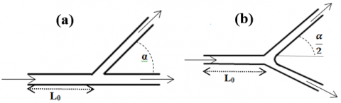
In this work, the laminar water flow is studied at a 2-D Y-shaped channel. Two types of Y-shaped channel are used as shown in Figure 1. The width (D) of the all sections of the both channels are 1 mm and is constant on all models. Both channels have three sections, inlet channel with the length equal of L0 (equal 10 times D) and two sections with outlets with the angle of α between two sections. In straight Y-shaped channel (Figure 1(a)), two outlet sections are named as main and side channel, respectively. In diagonal Y-shaped channel (Figure 1(b)), two outlet sections are named as up channel and down channel. Recirculation zones can be seen in both outlet sections. The Recirculation length is said as Lr. The ratio of Recirculation length to channel width (D) is used in the analysis of results as non-dimensional Recirculation length.
Figure 1. Geometries of two types of Y-shaped channel
3.1 CFD modeling
In this model, it is assumed that there is a steady-state flow of an incompressible fluid. Governing equations for these systems are consisted of continuity and momentum which are listed in Eqs. (1) - (3), respectively.
$\frac{\partial u}{\partial x}+\frac{\partial v}{\partial y}=0$ (1)
$u \frac{\partial u}{\partial x}+v \frac{\partial u}{\partial y}=-\frac{\partial P}{\partial x}+\mu\left[\frac{\partial^{2} u}{\partial x^{2}}+\frac{\partial^{2} u}{\partial y^{2}}\right]$ (2)
$u \frac{\partial v}{\partial x}+v \frac{\partial v}{\partial y}=-\frac{\partial P}{\partial y}++\mu\left[\frac{\partial^{2} v}{\partial x^{2}}+\frac{\partial^{2} v}{\partial y^{2}}\right]$ (3)
In the above equations, u and v are x and y component of velocity. No-slip condition is used for all walls. Inlet flow is water with specific velocity.
Governing equations (1-3) are solved with the finite volume method over control volume. First- order upwind discretization scheme was used for governing equations expect of pressure. The SIMPLE algorithm was employed to solve the convection-diffusion equations. The convergence criteria are 10-5 for all parameters. In thorough of control volume, Quad grids were used. Optimal size and type of grids were achieved with consideration vary grids for any model to ensure that the resolution of the mesh was not influencing the results.
3.2 Computational experiments
In this work, the DOE methodology is used. DOE methods present suitable information from a limited number of cases, so this method can be applied to CFD models which consumed a large time. From initial considerations, it can be found that the two parameters (angle and Reynolds number (Re)) can affect the Recirculation length. A set of computational experiments has been designed based on the Response Surface Methodology (RSM) as Central Composite Design (CCD) as design points (Table 1) with these two parameters. Run CFD models for design points and Response (as Recirculation length) are achieved. Then, with analysis of ANOVA (Analysis of variance), proposed correlation is predicted. Some verification points (Table 1) are used to check the validity of the proposed correlations.
Table 1. Design points from CCD method and Verification points for checking the validation of proposed model
|
Design Point |
Verification Point |
Verification Point |
||||||
|
|
α |
Re |
|
α |
Re |
|
α |
Re |
|
Run1 |
45 |
200 |
Run1 |
30 |
400 |
Run7 |
30 |
330 |
|
Run2 |
60 |
300 |
Run2 |
45 |
250 |
Run8 |
45 |
500 |
|
Run3 |
75 |
400 |
Run3 |
45 |
300 |
Run9 |
45 |
550 |
|
Run4 |
60 |
500 |
Run4 |
60 |
350 |
Run10 |
30 |
450 |
|
Run5 |
45 |
400 |
Run5 |
45 |
350 |
Run11 |
60 |
420 |
|
Run6 |
30 |
300 |
Run6 |
45 |
450 |
Run12 |
60 |
440 |
|
Run7 |
45 |
600 |
|
|
|
|
|
|
|
Run8 |
30 |
500 |
|
|
|
|
|
|
|
Run9 |
15 |
400 |
|
|
|
|
|
|
3.3 Validation of CFD modeling
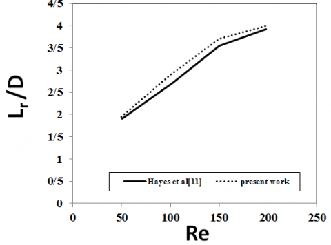
In this section, the validation of the model was considered by Hayes’s work [11]. The flow characteristics of a Newtonian fluid in a 90 degree branch was studied. The variation of non-dimensional recirculation length with varying Reynolds numbers is presented in Figure 2. The average percentage deviation of the values obtained in this study as compared with those given by Hayes et al. [11] is found to be about 4%.
Figure 2. Validation of the model
4.1 Initial considerations
Firstly, it should be to determine the effective parameters. Figure 3 shows recirculation zone in the straight Y-shaped channel. It can be seen that there are recirculation zones at each outlet section with length of Lr1 and Lr2. On the other hand, Figure 4 shows these two recirculation zones for two different Reynolds numbers while the angle is equal as 45º for both two models.
Figure 3. Two recirculation zones with length of Lr1 and Lr2 in straight Y-shaped channel (α=45º, Re=200)
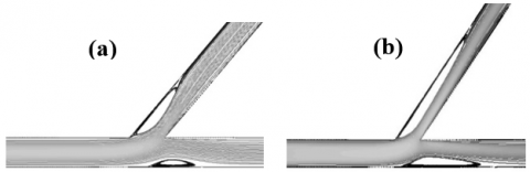
Figure 4. Effect of Reynolds number on two recirculation lengths in straight Y-shaped channel, α=45º, (a) Re=200, (b) Re=600
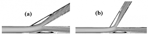
Another parameter that is expected to be affected on the recirculation length is the angle between two outlet sections (α). So in the next step, this parameter was considered. Figure 5 shows recirculation zones for two different angles while the Reynolds number is equal as 300 for both two models. The angle was affected on the recirculation length, but not as Reynolds number. Also, this effect on the Lr1 is much clear than Lr2. As it seems that with increasing the angle, the recirculation length decreases, however, this result must be considered more. Also, it seems the angle has less effect than the Reynolds number.
Figure 5. Effect of angle on two recirculation lengths in straight Y-shaped channel, Re=300, (a) α=30º, (b) α=60º
When fluid goes from main channel to side channel, fluid separated from the upper wall of the side branch and a recirculation region is formed, which is developed with increasing of Reynolds number. With increasing the Reynolds number and so results in increasing the velocity of fluid, this separation is more. Also, with changing the angle of the side branch, the contact angle of the fluid with the wall of the side branch is changed and can affect the length of the circulation of the fluid.
4.2 Consideration of Recirculation lengths in straight Y-shaped channel
In this section, results of CFD runs for design points (Table 1) were used to predict the correlations. Proposed correlation is a linear model (Eq. (4)) with coefficients that were listed in Table 2 and 3 for non-dimensional form of Lr1 and Lr2, respectively. Figure 6 shows the Lr/D values calculated by the proposed model versus those predicted by the CFD runs. It can be found that there is a fairly good agreement (±10% and ±15% Lr1/D and Lr2/D, respectively). For validation the proposed correlation, verification points (Table 1) are added to Figure 6 and it can be seen they exist in the above range.
$\frac{L_{r}}{D}=c_{0}+c_{1} * R e+c_{2} * \alpha$ (4)
Table 2. Value of coefficients of linear proposed model for Lr1
|
|
c0 |
c1 |
c2 |
|
|
0.71806 |
6.567E-3 |
-2.833E-3 |
Table 3. Value of coefficients of linear proposed model for Lr2
|
|
c0 |
c1 |
c2 |
|
|
1.8033 |
7.567E-3 |
-0.01244 |
Figure 6. Validation of the proposed linear correlation for the recirculation lengths calculation using verification points
4.2.1 Effect of the Reynolds number and angle on the recirculation length in straight Y-shaped channel
With proposed model, the effect of the Reynolds number and angle on both non-dimensional form of recirculation lengths, Lr1/D and Lr2/D was considered. Figure 7 shows the effect of these parameters on Lr1/D. From Figure 7(a) it can be seen with increasing the angle for three Reynolds number, Lr1 decreases slightly. As, when Re is 300, for 100 percent by increasing of angle (from 30º to 60º), Lr1/D decreases only 3%.
But Figure 7(b) shows that with increasing the Reynolds number for three angles, Lr1 increases. As when the angel is 30º, for 100 percent increasing by the Reynolds number (from 200 to 400), Lr1/D increases about 67 percent.
On the other hand, these results can be found for Lr2 but more intense. Figure 8 shows that with decreasing the angle and increasing the Reynolds number, Lr2 increases. But in this part, the effect of the angle is much clear than the previous section. As when Re is 300, for 100% increasing of angle (from 30º to 60º), Lr2 decreases 10%. However, like as the previous section, the effect of the Reynolds number is clear. As when the angel is 30º, for 100 percent increasing by the Reynolds number (from 200 to 400), Lr2 increases 52%.
By increasing the Reynolds number, the velocity of the fluid increases, so recirculation zones are developed. On the other hand, with changing the angle, in fact, the direction of inlet fluid to the second section of outlet channel changes and fluid more lead to the wall.
4.3 Consideration of Recirculation lengths in diagonal Y-shaped channel
In this section, above mentioned procedure was used to predict the correlation. In diagonal Y-shaped channel, because of the symmetry shape of the channel, the lengths of two recirculation zones at two outlet sections are equal. So, in this part only one recirculation length was named as Lr, was considered.
Figure 8. Effect of (a) angle and (b) Reynolds number on the recirculation length (Lr2)
Proposed correlation is a quadratic model (Eq. (5)) with coefficients that were listed in Table 4. From a comparison of Lr/D values calculated by the proposed model and CFD results, it can be found that like as the previous section, there is a fairly good agreement (±10%). In this part, verification points are used for validating the proposed correlation, too. For shortening the content and not repeating similar cases, the presentation of the related figure in this section was ignored.
$\frac{L_{r}}{D}=c_{0}+\sum_{i} c_{i} k_{i}+\sum_{j} c_{i j} k_{j}^{2}+\sum \sum_{i \neq j} c_{i j} k_{i} k_{j}$
$k_{i, j}=\alpha, \operatorname{Re}$ (5)
Table 4. Value of coefficients of Quadratic proposed model for Lr
|
|
1 |
Re |
α |
|
1 |
4.98743 |
4.617E-3 |
-0.13214 |
|
Re |
|
-2.3542E-6 |
-3.833E-5 |
|
α |
|
|
1.212E-3 |
4.3.1 Effect of the Reynolds number and angle on the recirculation length in diagonal Y-shaped channel
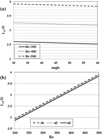
With the quadratic proposed model, the effect of the Reynolds number and angle on the non-dimensional form of recirculation lengths, Lr was considered as shown in Figure 9. FromFigure 9(a) it can be seen with increasing the angle for three Reynolds number, Lr significantlydecreases. However, with increasing the Reynolds number, the difference between these values of Lr becomes small. But Figure 9 (b) shows that with increasing the Reynolds number for three angles, Lr increases. However, this increasing in higher angle is less than lower angle. As, when the angel is 30º, for 100 percent increasing by the Reynolds number (from 200 to 400), Lr increases 15%, while this increasing for angle equal as 60 is 10%. From results, it can be found that in this structure of the Y-shaped channel, the angle is an important parameter and must be considered in studies.
Figure 9. Effect of (a) angle and (b) Reynolds number on the recirculation length (Lr)
The application of the Computational experiments for understanding of the fluid behavior was studied in the Y-shaped channel. Here is focused on the Recirculation zones and length. According to the results of this work, following conclusions have been made:
In diagonal Y-shaped channel, the angle is an important parameter and must be considered in studies.
|
D |
Width of channel, m |
|||
|
L0 |
Initial Length of channel, m |
|||
|
Lr |
Recirculation lengths |
|||
|
P |
Pressure, Pa |
|||
|
Re |
Reynolds Number |
|||
|
u |
x-component of velocity, m/s |
|||
|
v |
y-component of velocity, m/s |
|||
|
Greek symbols
|
|
|
||
|
a |
Angle of two branchs,deg |
|
||
|
µ |
dynamic viscosity, kg. m-1.s-1 |
|
||
Highlights
[1] Khandelwal V, Dhiman A, Baranyi L. (2015). Laminar flow of non-Newtonian shear-thinning fluids in a T-channel. Computers & Fluids 108: 79-91. https://doi.org/10.1016/j.compfluid.2014.11.030
[2] Liepsch D, Moravec S, Rastoci AK, Vlachos N.S. (1982). Measurement and calculation of laminar flow in a ninety degree bifurcation. Journal of Biomechanics 15(7): 473-485. https://doi.org/10.1016/0021-9290(82)90001-X
[3] Louda P, Kozel K, Prˇíhoda J, Beneš L, Kopácˇek T. (2011). Numerical solution of incompressible flow through branched channels. Computers & Fluids 46: 318-324. https://doi.org/10.1016/j.compfluid.2010.12.003
[4] Brameley JS, Dennis CR. (1984). The numerical solution of two-dimensional flow in a branching channel. Computers & Fluids 12(4): 339-355. https://doi.org/10.1016/0045-7930(84)90014-8
[5] Singh B, Singh H, Singh Sehgal S. (2013). CFD analysis of fluid flow parameters within A Y-shaped branched pipe. International Journal of Latest Trends in Engineering and Technology 2(2): 313-317.
[6] Uppin VS, Savannanavar RN, Paschapur V. (2017). Velocity effect investigation on the flow parameters in Y-Duct. International Journal of Advance Research and Innovative Ideas in Education 2(2): C-1476: 7-12.
[7] Kumar RS, Khadabadi UB. (2017). Investigation of flow parameters and structural analysis of Y-Duct. International Research Journal of Engineering and Technology 4(6): 1520-1524.
[8] Yadav S, Mallikarjuna Reddy M, Singh A. (2015). Shear-induced particle migration in three-dimensional bifurcation channel. International Journal of Multiphase Flow 76: 1-12.
https://doi.org/10.1016/j.ijmultiphaseflow.2015.06.007
[9] Versteeg HK, Malalasekera W. (1995). An Introduction to Computational Fluid Dynamics – The Finite Volume Method. John wiley & sons Inc.
[10] Taghavifar H, Jafarmadar S, Taghavifar H, Navid A. (2016). Application of DoE evaluation to introduce the optimum injection strategy-chamber geometry of diesel engine using surrogate epsilon-SVR. Applied Thermal Engineering 106: 56-66.
https://doi.org/10.1016/j.applthermaleng.2016.05.194
[11] Hayes RE, Nandakumar K, Naser-El-Din H. (1989). Steady laminar flow in a 90 degree planar branch. Computers & Fluids 17(4): 537-553. https://doi.org/10.1016/0045-7930(89)90027-3