OPEN ACCESS
The aim of the present paper is to determinate the optimal correction of thermal bridges in buildings refurbishment, taking into account the minimum insulation requirements provided by Italian legislation. The Decree 26.06.2015, transposing the directive 2010/31/EU, imposes the respect of limit values of the mean thermal transmittance of building components and of the mean global heat transmission coefficient of entire façades. Both such parameters include thermal bridges contribution. A 30% derogation on mean thermal transmittance limit values is allowed in case of filling wall cavities of buildings, object of simple energy refurbishment, with insulating materials. A case study, concerning a building façade repetitive module with door window, balcony and roller shutter box, is considered; in addition to junctions due to beams and pillars, the thermal bridges due to lintel, threshold, jambs and balcony are examined. An aerogel insulating material is used for their correction. The linear thermal transmittance is determined by a 2-D numerical model. Results show that it is very difficult to respect the limit values for the mean thermal transmittance; it is possible to comply the limit values for mean global heat transmission coefficient using high performance windows.
thermal bridges, mean thermal transmittance, mean global heat transmission coefficient, aerogel insulating material, energy refurbishment of buildings, 2-D numerical simulation
Retrofitting of existing buildings plays a critical role to achieve sustainable development. In fact, the building sector is one of the largest energy consumers and GHG emitters [1]. Building energy consumption sums up to 40% of primary energy consumption in the world. Improving the energy efficiency in buildings is vital to address the climate change and achieve energy independence [2].
Several actions have been taken by the European Commission to reduce buildings energy consumption through many revisions of Energy Performance Building Directives (EPBD) [3-5].
In Italy, some mandatory laws have come into force to transpose European Directives [6]. In particular, the Decree 26.06.2015 [7], concerning minimum requirements of new and existing buildings object of energy refurbishment, fixes limit values for the following parameters referred to the building envelope:
mean thermal transmittance Um of single opaque elements to be respected in both cases of simple energy refurbishment, that involves a surface ≤ 25% of the total gross leaking building surface, and major 2nd level energy renovation, that involves a surface > 25% of the total gross leaking building surface;
mean global heat transmission coefficient H'T of an entire façade including opaque and glazed elements to be respected in case of major 2nd level energy renovation, as above defined.
Moreover, in case of simple energy refurbishment, a 30% derogation on limit values of mean thermal transmittance is allowed in two cases: insulation of the inner part of building elements and filling cavity walls of existing buildings with insulating materials. This derogation is not allowed in case of important 2nd level energy renovation.
The cavity insulation is very significant, since almost all Italian '45-'80 years residential buildings were built in reinforced concrete frame structure with beams and pillars completed by cavity wall technique.
In an urban contest, an eventual coat insulation increases wall thickness and frequently is hardly achievable due to limited available distances among buildings and to property border reasons. Moreover, coat insulation of external walls frequently requires extra works, i.e. thresholds and lintels substitution, eventual new displacement of water and gas pipes, reposition of shutters and reconstruction of architectural and decorative elements. On the other hand, internal insulation leads to a reduction of net indoor spaces and involves the risk of interstitial condensation [8, 9].
A useful technique is therefore to fill the air layer with granular insulating materials. The main problem related to this technology is the failure of thermal bridges correction with consequent higher energy needs and risk of mould growth. A study concerning buildings in Greece [10] has demonstrated that buildings heating need in case of insulated wall cavities without thermal bridges correction is by 50% higher than the one calculated for the more recent buildings with coat insulations and thermal bridges correction. Consequently, a low thickness insulation of thermal bridges with a high performance insulating material is necessary to reduce building envelope energy need. A study concerning thermal bridges correction in a dwelling by means of cork-based mortars is developed in [11]. In [12] an aerogel insulating coating is used to limit windows offset thermal bridge effects: applying 1 cm to 2 cm of insulation reduces the windows offset energy load by about 24–50%.
In previous papers [13,14], the authors demonstrated that the mean thermal transmittance limit values imposed by Decree 26.06.2015 are impossible to be comply without a correction of thermal bridges, even in the presence of derogation. A simple case study concerning an opaque vertical wall with thermal bridges due to beams and pillars has been investigated in [13]. A more complex case concerning a typical repetitive module of a building façade with window, sub window and roller shutter box is analysed in [14].
The purpose of this paper is to study a further typical case consisting of a repetitive module of building façade with door window, balcony and roller shutter box. In addition to junctions due to beams and pillars, thermal bridges due to lintel, threshold, jambs and balcony are examined. The linear thermal transmittance y is calculated according to standard UNI EN ISO 10211 [15] by means of the 2-D finite element simulator THERM [16].
Starting from the actual state of an uninsulated building and considering the insulation of cavity wall, the correction of the thermal bridges necessary to respect limit values of both mean thermal transmittance Um and mean global heat transmission coefficient H'T is discussed. The insulation is achieved by an aerogel layer characterized by a very low declared thermal conductivity.
The Decree 26.06.2015 [7], concerning minimum energy targets in buildings, distinguishes the interventions of building envelope energy retrofitting in three categories:
For each of the aforementioned categories, different minimum targets are provided.
In the case of major 1st level renovations, it is necessary to comply with the requirements concerning the complex of the building-plant system and not individual building components or façades. This category is not considered in the present study.
In the case of major 2nd level renovations, the decree imposes the compliance of the mean global heat transmission coefficient H'T [17], referred to the whole surface with the same orientation and concerning the entire façade or a portion of it. The present research takes into account only vertical façades. The H'T coefficient is defined as:
$\mathrm{H}_{\mathrm{T}}^{\prime}=\frac{\mathrm{H}_{\mathrm{t}, \mathrm{adj}}}{\sum_{\mathrm{k}} \mathrm{A}_{\mathrm{k}}}$ (1)
Htr,adj=overall heat transfer coefficient by transmission, adjusted for the indoor-outdoor temperature difference
Ak=gross projected area of the -k element (opaque or transparent) which is part of the exchange surface under analysis
Limit values for H'T coefficient are reported in Table 1 as a function of the local climatic zone of the Italian territory, according to heating degree days (cumulated temperature differences), defined by UNI EN ISO 10349-3 [18] and established by the Decree of President of the Republic 26.08.1993 no. 412 [19].
Table 1. Limit H'T values for major 2nd level energy renovation
|
Climatic zone |
H'T (W m-2K-1) |
|
A, B |
0.73 |
|
C |
0.70 |
|
D |
0.68 |
|
E |
0.65 |
|
F |
0.62 |
The decree allows a 30% derogation on limit values in both cases of insulation on the internal part of the building elements and filling the cavity wall with insulating materials. Such derogation is valid only for simple energy refurbishments, while the major 2nd level renovations are excluded.
Thermal transmittance limit values for opaque vertical components are reported in Table 2 for both absence and presence of derogation. For each climatic zone, two limit values are provided: the first one is immediately operative, while the second one will come into force from January 1st, 2021 in conjunction with the requirement to realize NZEB buildings.
Table 2. Limit U values for opaque vertical elements and derogated values (+30%) in case of internal and cavity insulation
|
Climatic zone |
U [W m-2K-1] limit |
U [W m-2K-1] derogation |
||
|
2015 |
2021 |
2015 |
2021 |
|
|
A, B |
0.45 |
0.40 |
0.59 |
0.52 |
|
C |
0.40 |
0.36 |
0.52 |
0.47 |
|
D |
0.36 |
0.32 |
0.47 |
0.42 |
|
E |
0.30 |
0.28 |
0.39 |
0.36 |
|
F |
0.28 |
0.26 |
0.36 |
0.34 |
A very common case study has been investigated. Most of Italian buildings dating back to the '45-'80 years are characterized by frames with beams and pillars in reinforced concrete with cavity wall masonry completion. A building façade, consisting of a repetitive module with door window, balcony and roller shutter box, is considered (Figure 1). The module has a gross length of 5 m and a gross height of 3.3 m; its gross area is Amod = 16.5 m2. Pillars are 35 cm thick and 30 cm wide. There are no dividing walls behind the pillars. Floors have a 30 cm thickness. Two different lengths of balcony are considered: 3 m (Figure 1a) and 1.8 m (Figure 1b). Balcony is 1.1 m protruding and 25 cm thick.
Figure 1. Repetitive module
The current wall presents a 15 cm tick cavity and its stratigraphy is reported in Table 3. Thermal conductivities of materials are provided by the standards UNI 10351 [20], UNI EN ISO 10456 [21] and UNI/TR 11552 [22]. Conventional surface resistances of UNI EN ISO 6946 [23] are used.
Table 3 provides thermal transmittance for both cases, non-insulated and insulated cavity wall. Insulation is achieved by filling the air layer with a traditional insulating material ($\lambda$= 0.037 W m-1K-1). Note that the insulated wall transmittance value is in the range allowed by the decree (Table 2), but it does not take into account the influence of thermal bridges.
Table 3. Non-insulated and insulated cavity wall stratigraphy
|
|
Layer |
Thickness(cm) |
$\lambda$ (W m-1K-1) |
R (m2K W-1) |
|
|
Internal surface |
0.130 |
||
|
1 |
Internal plaster |
1 |
0.700 |
0.014 |
|
2 |
Air brick |
8 |
0.200 |
|
|
3 |
Air |
15 |
0.180 |
|
|
Insulation |
0.037 |
4.054 |
||
|
4 |
Air brick |
12 |
0.310 |
|
|
5 |
External plaster |
4 |
0.900 |
0.044 |
|
|
External surface |
0.040 |
||
|
|
Total thickness |
40 |
||
|
|
Non-insulated cavity wall R (m2K W-1) U (W m-2K-1) |
0.919 1.09 |
||
|
|
Insulated cavity wall R (m2K W-1) U (W m-2K-1) |
4.793 0.21 |
||
It is also necessary to hypothesize geometrical, constructive and thermal characteristics of door window and roller shutter box.
A door window constituted by a 6 cm thick PVC frame section (Uf = 2.12 W m-2K-1) and double glazed (4-12-4 mm) with air cavity (Ug = 1.88 W m-2K-1) and common spacer ($\psi_{\mathrm{g}}$= 0.07 W m-1K-1) is assumed. Thermal transmittances of the frame, glass and spacer are calculated according to UNI EN ISO 10077-2 [24]. Thermal transmittance of window, according to UNI EN ISO 10077-1 [25] is 2.08 W m-2K-1.
Table 4. Pillar stratigraphy
|
|
Layer |
Thickness (cm) |
$\lambda$ (W m-1K-1) |
R (m2K W-1) |
|
|
Internal surface |
0.130 |
||
|
1 |
Internal plaster |
1 |
0.700 |
0.014 |
|
6 |
Pillar |
35 |
1.910 |
0.183 |
|
5 |
External plaster |
4 |
0.900 |
0.044 |
|
|
External surface |
0.040 |
||
|
|
Total thickness |
40 |
||
|
|
Pillar R (m2K W-1) U (W m-2K-1) |
0.412 2.43 |
||
|
|
Layer |
Thickness (cm) |
$\lambda$ (W m-1K-1) |
R (m2K W-1) |
|
|
Bottom surface |
0.100 |
||
|
1 |
Internal plaster |
1 |
0.700 |
0.014 |
|
7 |
Slab and masonry |
22 |
|
0.330 |
|
8 |
Concrete screed |
4 |
1.060 |
0.038 |
|
9 |
Cement mortar |
1.5 |
1.400 |
0.011 |
|
10 |
Stoneware tiles |
1.5 |
1.470 |
0.010 |
|
|
Upper surface |
0.170 |
||
|
|
Total thickness |
30 |
||
|
|
Floor R (m2K W-1) U (W m-2K-1) |
0.673 1.49 |
||
Figure 2. Building elements and thermal bridges of the repetitive module
Figure 3. Pillar-current wall thermal bridge (pc)
Figure 4. Door window-current wall thermal bridge (wc) and roller shutter box-current wall thermal bridge (rc)
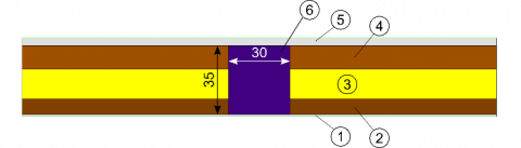
Figure 5. Beam-current wall thermal bridge (bc) and balcony-current wall thermal bridge (bac)
A non-insulated soft wood ($\lambda$= 0.13 W m-1K-1) 5 mm thick roller shutter box is considered, with thermal characteristics and geometry according to UNI EN ISO 10077-2. The roller shutter box has the same length as the door window and its depth is about 30 cm, with a thermal transmittance of 5.06 W m-2K-1.
Figure 2 shows the nomenclature used in the present study for both buildings elements and thermal bridges that compete to the repetitive module. Figure 2 also reports geometrical sizes used in the calculations.
Figures 3-6 sketch thermal bridges constructive details. They correspond to THERM models [16]. In particular, light green lines represent boundary conditions. Numbers are referred to stratigraphies reported in Tables 3-5; sizes are expressed in cm.
L-shaped border beam, identified by number 11 in Figures 5 and 6, is 60 cm high and 15 cm thick and it is characterized by the same conductivity of pillars ($\lambda$= 1.91 W m-1K-1). The marble slab of the door window threshold, identified by number 12 in Figure 6, is 15 mm thick with $\lambda$= 3 W m-1K-1.
Figure 6. Roller shutter box-balcony-door window thermal bridge (rbaw)
Linear thermal transmittances $\psi$ of thermal bridges have been calculated by a finite element 2-D model, according to UNI EN ISO 10211 [15]. Calculations have been carried out by THERM [16], a finite-element simulator developed at Lawrence Berkeley National Laboratory (LBNL). In general:
$\psi=\mathrm{L}_{2 \mathrm{D}}-\sum_{\mathrm{i}} \mathrm{L}_{\mathrm{i}} \mathrm{U}_{\mathrm{i}}$ (2)
L2D=thermal coupling coefficient obtained from the 2-D calculation
Ui=thermal transmittance of the 1-D i-th component
Li=length over which the value Ui applies
The calculation method has been previously tested and validated in accordance to case-studies A.1 and A.2 of Annex A of UNI EN ISO 10211. The values of $\psi$bc and $\psi$bac and $\psi$rbaw have been estimated referring calculations to internal measures, according to UNI EN ISO 14683 [26].
The mean thermal transmittance Um of the repetitive module, to be compared with Table 2 limit values, is calculated by the following relation:
$\mathrm{U}_{\mathrm{m}}=\frac{\mathrm{U}_{\mathrm{c}} \mathrm{A}_{\mathrm{c}}+\sum_{\mathrm{i}} \psi_{\mathrm{i}} \mathrm{L}_{\mathrm{i}}}{\mathrm{A}_{\mathrm{op}}}$ (3)
Aop = Amod - Aw - Ar, opaque gross area of repetitive module
Ac = Hp Lb, opaque net area of repetitive module
Uc = thermal transmittance of current wall of area Ac
The contribution of all thermal bridges that compete to the repetitive module is (Figure 2):
$\begin{align} & \sum\nolimits_{i}{{{\psi }_{i}}{{L}_{i}}}={{\psi }_{pc}}{{H}_{p}}+2{{\psi }_{wc}}{{H}_{w}}+2{{\psi }_{rc}}{{H}_{r}}+ \\ & +{{\psi }_{bc}}({{L}_{b}}-{{L}_{ba}})+{{\psi }_{bac}}({{L}_{ba}}-{{L}_{w}})+{{\psi }_{rbaw}}{{L}_{w}} \\ \end{align}$(4)
$\psi$pc=linear thermal transmittance of pillar-current wall thermal bridge of length Hp (see Figure 3)
$\psi$wc=linear thermal transmittance of window-current wall thermal bridge of length Hw (see Figure 4)
$\psi$rc=linear thermal transmittance of roller shutter box-current wall thermal bridge of length Hr (see Figure 4)
$\psi$bc=linear thermal transmittance of beam-current wall thermal bridge of length (Lb-Lba) (see Figure 5)
$\psi$bac=linear thermal transmittance of balcony-current wall thermal bridge of length (Lba-Lw) (see Figure 5)
$\psi$rbaw=linear thermal transmittance of roller shutter box-balcony-window thermal bridge of length Lw (see Figure 6)
The mean global heat transmission coefficient H'T of the repetitive module, to be compared with Table 1 limit values, is evaluated as:
$\mathrm{H}_{\mathrm{T}}^{\prime}=\frac{\mathrm{U}_{\mathrm{m}} \mathrm{A}_{\mathrm{op}}+\mathrm{U}_{\mathrm{w}} \mathrm{A}_{\mathrm{w}}+\mathrm{U}_{\mathrm{r}} \mathrm{A}_{\mathrm{r}}}{\mathrm{A}_{\mathrm{mod}}}$ (5)
Uw = thermal transmittance of door window of area Aw
Ur = thermal transmittance of roller shutter box of area Ar
In Table 6 calculated mean thermal transmittance Um and mean global heat transmission coefficient H'T are reported for the repetitive module for both 1.8 m and 3 m balcony lengths and for both non-insulated and insulated wall cavities. Results are very far from respecting limits values shown in Tables 1 and 2, even in case of derogation on the mean thermal transmittance.
Table 6. Um and H'T of non-insulated and insulated wall cavities
|
|
|
Um (W m-2K-1) |
H'T (W m-2K-1) |
||
|
Cavity wall |
Balcony length |
1.8 m |
3 m |
1.8 m |
3 m |
|
Not insulated |
|
1.68 |
1.65 |
1.91 |
1.88 |
|
Insulated |
|
0.93 |
0.92 |
1.21 |
1.21 |
A 2 cm thick aerogel layer, identified by number 13 in Figures 4 and 6, is applied inside the roller shutter box leading its thermal transmittance to 1.10 W m-2K-1.
Owing to the small thickness of external plaster used in buildings of '45-'80 years, no more than 2¸3 cm of useful thickness are available in order to insulate thermal bridges from outside and to maintain the original vertical shape of the façade.
Correction of vertical thermal bridges (pc), (wc) and (rc) is obtained in the same way as described in [14]. In particular, for the pillar-current wall bridge (pc), the insulation exceeds by 15 cm the pillar width from the right and left sides.
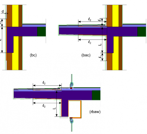
Correction of horizontal thermal bridges is depicted in Figure 7, where L is the beam width and d represents the aerogel thickness.
For the (bc) bridge $\ell_{1}$ dimension is referred to the aerogel that exceeds L dimension applied above and below the beam. For the (bac) bridge $\ell_{1}$ is referred to the aerogel surplus applied below the beam and $\ell_{2}$ to the aerogel surplus applied under and above the balcony. Finally, for the (rbaw) bridge $\ell_{2}$ is referred to the aerogel surplus applied under and above the balcony.
The effect of $\ell_{1}$ and $\ell_{2}$ parameters is considered by means of the percentage surplus ratios SR1 and SR2, defined as follows:
$\mathrm{SR}_{1}=\frac{\ell_{1}}{\mathrm{L}} \cdot 100 \quad \mathrm{SR}_{2}=\frac{\ell_{2}}{\mathrm{L}} \cdot 100$ (6)
In order to correct the thermal bridge (rbaw), an aerogel layer 1 cm thick is applied on the inner side of the beam, inside the roller shutter box, as shown in Figure 7.
Figure 7. Correction of thermal bridges (bc), (bac) and (rbaw)
Several simulations were carried out in order to verify if the proposed thermal bridges corrections allow to respect the mandatory limits.
In Figure 8 mean thermal transmittance Um versus SR1 and SR2 parameters for both considered balcony lengths 1.8 m and 3 m is shown. Two different cases are discussed: the aerogel panel is applied only under the balcony (1) and the aerogel panel is applied both under and above the balcony (2). In all cases aerogel panel is 1 cm thick.
Examination of Figure 8 reveals that the application of the insulation above the balcony under floor tiles produces a negligible effect on Um: for this reason, since it is in any case an invasive intervention, in the subsequent simulations it has not been taken into consideration.
Limit thermal transmittances values at 2021 in presence of derogation for simple energy refurbishment are also reported in Figure 8. It can be noted that calculated Um values are far from limit values for all climatic zones. Even more difficult is the compliance with the Um limit in the case of major 2nd level energy renovations, where no derogation is admitted.
Figure 8. Mean thermal transmittance Um versus SR1 and SR2 for balcony lengths of 1.8 m and 3 m in presence (2) and in absence (1) of insulation above the balcony, d = 1 cm
It was therefore investigated whether, by increasing the aerogel thickness, it is possible to achieve compliance with the limit values.
The thickness of aerogel panels was increased to 3 cm on all thermal bridges, both horizontal and vertical. Only the correction of the lower part of the balcony and of the inner side of the beam has been maintained with a thickness of 1 cm for technical reasons.
Results are reported in Figure 9, where the two different aerogel thicknesses d = 1 cm and d = 3 cm are compared.
Figure 9. Influence of aerogel thickness d: Um versus SR1 and SR2 for balcony lengths of 1.8 m and 3 m
Figure 9 reveals that a 3 cm insulation thick allows to comply the derogated transmittances at 2021 only in A and B climatic zones. In particular, the compliance occurs for SR1 and SR2 greater than 10%-20% for 1.8 m balcony, for SR1 and SR2 greater than 30%-60% for 3 m balcony. Actual derogated limit transmittances (at 2015) can be complied also in climatic zone C. Limit values are not respected in other climatic zones.
The influence of thermal bridges on the heat flux through the opaque wall is shown in Figure 10 for panel thickness d = 3 cm and balcony length Lba = 1.8 m, that is the most favourable case among those shown in Figure 9.
The contribution of thermal bridges is equal to 61.9%, while that of the current wall is equal to 38.1%. The percentage contribution of single thermal bridges is also reported in Figure 10.
It can be noted that the greatest contribution (23.7%) is given by the horizontal thermal bridge (rbaw), mainly due to the joint between the door window frame and the marble slab. The weights of the beam horizontal thermal bridges (bac) and (bc) (in total 18.6%) and of the pillar vertical thermal bridge (pc) (15%) are comparable, while the weight of the vertical thermal bridges (wc) and (rc) (in total 4.7%) is negligible.
In the same conditions as in Figure 9, the mean global heat transmission coefficient H'T has been calculated. Results are depicted in Figure 11. No compliance with limit values at 2021 occurs due to the door window low performance (Uw = 2.08 W m-2K-1).
Figure 10. Influence of thermal bridges on the heat flux through the opaque wall, d = 3 cm, Lba = 1.8 m
Figure 11. H'T versus SR1 and SR2 for balcony lengths of 1.8 m and 3 m and insulation thick of 1 cm and 3 cm
Table 7. Maximum Uw values to comply limit H'T values at 2021 for major 2nd level energy renovation
|
Uw (W m-2K-1) |
||
|
Climatic zone |
Lba = 3 m |
Lba = 1.8 m |
|
A, B |
1.42 |
1.51 |
|
C |
1.28 |
1.38 |
|
D |
1.19 |
1.29 |
|
E |
1.05 |
1.15 |
|
F |
0.92 |
1.01 |
Envelope energy refurbishment of buildings by means of filling wall cavities with insulating material and thermal bridge correction has been carried out, taking into account limit values on thermal transmittance Um and mean global heat transmission coefficient H'T provided by Italian DM 26.06.2015. A repetitive module containing door window, roller shutter box and balcony has been considered. Thermal bridges correction is achieved by aerogel panels. The following conclusions can be drawn:
· application of the aerogel panel under the balcony floor tiles produces a negligible effect on Um;
· application of 3 cm thick aerogel panel on all thermal bridges allows to comply derogated Um limit values at 2021 only in A and B climatic zones;
· mean transmittance Um decreases as the length of the balcony decreases;
· compliance with H'T limit values is possible using high performances windows with transmittance values between 1.5 W m-2K-1 and 0.9 W m-2K-1, according to the climatic zone.
This research was funded by the research project PRA2017 of the University of Genoa.
|
A |
area (m2) |
|
H |
height (m) |
|
H'T |
mean global heat transmission coefficient (W m-2K-1) |
|
Htr,adj |
overall heat transfer coefficient (W K-1) |
|
L |
length (m) |
|
L2D |
thermal coupling coefficient (W m-1K-1) |
|
R |
thermal resistence (m2K W-1) |
|
SR |
surplus ratio (%) |
|
U |
thermal transmittance (W m-2K-1) |
|
d |
aerogel panel thickness (m) |
|
$\ell$ |
surplus length (m) |
|
Greek symbols |
|
|
$\lambda$ |
thermal conductivity (W m-1K-1) |
|
$\Psi$ |
linear thermal transmittance (W m-1K-1) |
|
Subscripts |
|
|
1 |
referred to aerogel vertical surplus |
|
2 |
referred to aerogel horizontal surplus |
|
b |
beam |
|
ba |
balcony |
|
bac |
balcony-current wall thermal bridge |
|
bc |
beam-current wall thermal bridge |
|
c |
current wall |
|
f |
frame |
|
g |
glass |
|
m |
mean |
|
mod |
module |
|
op |
opaque |
|
p |
pillar |
|
pc |
pillar-current wall thermal bridge |
|
r |
roller shutter box |
|
rbaw |
roller shutter box-balcony-door window thermal bridge |
|
rc |
roller shutter box-current wall thermal bridge |
|
w |
door window (see Figure 2) |
|
wc |
door window-current wall thermal bridge |
[1] Zhou Z, Zhang S, Wang C, Zuo J, He Q, Rameezdeen R. (2015). Achieving energy efficient buildings via retrofitting of existing buildings: a case study. Journal of Cleaner Production 112: 3605-3615. https://doi.org/10.1016/j.jclepro.2015.09.046
[2] Ruparathna R, Hewage K, Sadiq R. (2016). Improving the energy efficiency of the existing building stock: A critical review of commercial and institutional buildings. Renew Sustain Energy Rev 53: 1032-1045. https://doi.org/10.1016/j.rser.2015.09.084
[3] European Parliament. (2002). Directive 2002/91/EC. Vol L 1/65. Official Journal of the European Union 65-71. https://doi.org/10.1016/j.jclepro.2010.02.014
[4] European Parliament. (2010). Directive 2010/31/EU. Vol L153/13. Official Journal of the European Union 13-35. https://doi.org/10.3000/17252555.L_2010.153.eng
[5] European Parliament. (2012). Directive 2012/27/EU. Vol L315/1. Official Journal of the European Union 1-56. https://doi.org/10.3000/19770677.L_2012.315.eng
[6] Mazzarella L. (2015). Energy retrofit of historic and existing buildings. the legislative and regulatory point of view. Energy Build 95: 23-31. https://doi.org/10.1016/j.enbuild.2014.10.073
[7] Ministry of Economic Development. (2015). Applying the Methods of Calculating Energy Performance and Definition of Requirements and Minimum Standards of Buildings. GU Italian Republic no. 162 of 15-07-2015 - Ordinary supplement n.39.
[8] Marincioni V, May N, Altamirano-Medina H. (2015). Parametric study on the impact of thermal bridges on the heat loss of internally insulated buildings. Energy Procedia 78: 889-894. https://doi.org/10.1016/j.egypro.2015.11.013
[9] Cuce E, Cuce PM. (2016). The impact of internal aerogel retrofitting on the thermal bridges of residential buildings: An experimental and statistical research. Energy Build 116: 449-454. https://doi.org/10.1016/j.enbuild.2016.01.033
[10] Theodosiou TG, Papadopoulos AM. (2008). The impact of thermal bridges on the energy demand of buildings with double brick wall constructions. Energy Build 40(11): 2083-2089. https://doi.org/10.1016/j.enbuild.2008.06.006
[11] Theodosiou TG, Papadopoulos AM. (2008). The impact of thermal bridges on the energy demand of buildings with double brick wall constructions. Energy and Buildings 40: 2083-2089.
[12] Brás A, Gonçalves F, Faustino P. (2014). Cork-based mortars for thermal bridges correction in a dwelling: Thermal performance and cost evaluation. Energy Build 72: 296-308. https://doi.org/10.1016/j.enbuild.2013.12.022
[13] Ibrahim M, Biwole PH, Wurtz E, Achard P. (2014). Limiting windows offset thermal bridge losses using a new insulating coating. Appl Energy 123: 220-231. https://doi.org/10.1016/j.apenergy.2014.02.043
[14] Bergero S, Cavalletti P, Chiari A. (2016). Thermal bridge correction in energy refurbishment of existing buildings: a case study. In: Advanced Building Skins GmbH, ed. Proceedings of the Advanced Building Skins Conference Bern: CHE 2016:147-157.
[15] Bergero S, Cavalletti P, Chiari A. (2017). Energy refurbishment in existing buildings: Thermal bridge correction according to DM 26/06/2015 limit values. In: Energy Procedia 140: 127-140. https://doi.org/10.1016/j.egypro.2017.11.129
[16] UNI EN ISO 10211:2008. (2008). Thermal Bridges in Building Constructions. Heat Flows and Surface Temperatures. Detailed Calculations.
[17] Lawrence Berkeley National Laboratory (LBNL). THERM Finite Element Simulator (version 7.4.3.0). https://windows.lbl.gov/software/therm/therm.html
[18] Cavalletti P, Bergero S. (2016). The mean heat transmission coefficient as a new parameter to control heat transmission and mould growth in building refurbishing. J Civ Eng Archit Res 3(6): 1495-1502.
[19] UNI EN ISO 10349-3. (2016). Heating and Cooling of Buildings. Climatic Data. Part 3: Accumulated Temperature Differences (Degree-Days) and Other Indices.
[20] President of Republic. (1993). Regulation Containing Prescriptions for the Design, Installation, Operation and Maintenance of Heating Systems in Buildings in Order to Limit Energy Consumption, Implementing Art. 4, Par. 4 of Low 9 January 1991, N. 10. GU Italian Republic no. 242 of 14-10-1993 - Ordinary supplement n.96; 1993.
[21] UNI 10351. (2015). Building Materials and Products. Hygrothermal Proprieties. Procedure for Determining the Design Values.
[22] UNI EN ISO 10456. (2008). Building Materials and Products. Hygrotherrnal Properties. Tabulated Design Values and Procedures for Determining Declared and Design Thermal Values.
[23] UNI/TR 11552. (2014). Opaque Envelope Components of Buildings. Thermo-Physical Parameters.
[24] UNI EN ISO 6946. (2008). Building Components and Building Elements. Thermal Resistance and Thermal Transmittance. Calculation Method.
[25] UNI EN ISO 10077-2. (2012). Thermal Performance of Windows, Doors and Shutters. Calculation of Thermal Transmittance. Part 2: Numerical Method for Frames.
[26] UNI EN ISO 10077-1. (2007). Thermal Performance of Windows, Doors and Shutters. Calculation of Thermal Transmittance. Part 2: General.
[27] UNI EN ISO 14683. (2008). Thermal bridges in building construction. Linear thermal transmittance. Simplified Methods and Default Values.