OPEN ACCESS
In the field operation of heavy oil box-type substation, the overall arrangement is compact, which leads to the decrease of heat sink capacity and the "heat island effect", which leads to the increase of the temperature of the box-type substation. In this paper, the thermal equilibrium model of the box-type power station was established and the temperature field distribution and air flow of the box-type power station were simulated. The results showed that the parallel vertical layout program is not conducive to the air flow of the box, resulting in rising of the temperature around the plant, especially the box body temperature. According to the heat dissipation theory of blinds, the box-type power station is rearranged. The distribution of temperature field in tank power station with different container inclination under natural ventilation and no-wind condition were researched. The results show that the shutter layout can significantly reduce the temperature between the containers. When the inclination angle is 45 °, the heat balance effect is the best. In order to study the comprehensive effect of spacing and angle on the heat dissipation of the box-type power station, the orthogonal test was used to optimize the distance and angle of the container of the box-type power station. The results show that the heat balance effect is the best when the container spacing is 8m and the inclination angle is 45 °. The calculation results provide a basis for the cooling of the box-type power plant, thereby improving the operation efficiency of the power station and reducing the cost of establishing the station.
box-type substation, louver arrangement, optimization analysis, thermal equilibrium analysis
At present, box-type diesel generator sets are more and more popular with customers due to their high flexibility. Especially in some countries rich in oil resources, the number of small-scale power plants has been increasing, It is the key to speeding up the establishment of stations and reducing the cost of establishing stations [1]. However, the power of existing units mostly below 1000kW, and the price is very expensive, if we want to set up large scale power plant, it requires more number of units. This makes the cost too high, the amount of maintenance and engineering work is huge. This does not adapt to the growing demand for electricity in the region [2]. In order to adopt large-scale unit, the diesel generator set box installation, fast transportation, the overall layout of the design becomes a difficult [3].
When working in a power plant, ambient temperature has an important impact on the durability of its expensive components, and the most common method is to use the
highest hot spot temperature [4-5]. Few articles analyze the power plant equipment air, surface temperature And wind speed [6-7].At the same time, the overall layout of the heavy oil box power station in the field operation is too tight, which leads to the decrease of the radiator cooling capacity and "the heat island effect". The field environment is poor, the diesel exhaust gas and oil on the ground lead to radiator pollution, to further reduce the heat transfer efficiency
Foreign scholars have done some research to improve the heat transfer rate. J.M. Gorman and others studied louver fin and parallel fin heat exchangers for heat transfer characteristics, The results show that the heat exchange rate of louvered fin heat exchanger can be greatly increased [8].The Jiin-YuhJang's group used conjugate gradient method to optimize initial inclination angle and the inclination angle of the fin heat exchanger , and the simulation results are verified by experiments,the results show that the error of the simulation results and the experimental results is 12%. [9].Similarly, Ching-Tsun Hsieh's group further study the three-dimensional heat transfer and fluid flow analysis of the louvered [10], the results show that when compared with the initial layout, the changed device’s heat transfer enhancement of is increased by 118%, which indicates the variable angle louver structure can effectively improve the heat transfer efficiency.
Moreover, a lot of scholars have carried on the thorough research, Based on the ordinary rectangular blinds, Yang Lin et al. Proposed a new type of oblique-shaped blinds and established a three-dimensional numerical model of air flow in the oblique-shaped blinds. The numerical results were compared with the empirical correlations, The results show that the window fin angle has an important influence on the heat transfer of the shutter fins[11]. Kou Lei et al on the different blinds and louver spacing model was calculated and found that the angle of inclination of the louver fins for the best 27 ° heat transfer. The finest fin spacing is different, and the best shutter spacing of the corresponding heat transfer is different. The drag force increases with the increase of the louver angle and louver spacing, the results provide a basis for the optimal design of heat dissipation l ayout[12].
In conclusion, louver layout can effectively improve the heat transfer rate. Based on the actual situation of the box-type power plant, this paper proposed a blind type layout scheme suitable for the power station, and established a heat balance calculation model, analyzed the temperature field distribution and air flow status parameters of the power station. On this basis, the overall layout of the power plant is optimized, and the optimal layout scheme is obtained.
2.1 Basic theory
There are three basic equations of fluid mechanics:
Continuity equation:
$\frac{\partial \rho }{\partial \text{t}}+\rho \nabla \text{gVr}=\text{0}$
Navier-Stokes equations:
$\frac{\text{DV}}{\partial \text{t}}=f-\frac{1}{\rho }({\mu }'+\frac{1}{3}\mu )\nabla (\nabla \bullet V)+\frac{1}{\rho }\mu {{\nabla }^{2}}V$
Energy equation:
$\frac{\text{De}}{\partial \text{t}}=\text{-P}\frac{\text{D}}{\text{Dt}}\left( \frac{1}{\rho } \right)+\varphi +\frac{1}{\rho }\frac{\partial }{\partial {{\text{x}}_{\text{i}}}}\left( \lambda \frac{\partial \text{T}}{\partial {{\text{x}}_{\text{i}}}} \right)+{{\text{q}}_{\text{R}}}$
For the air, when the velocity is less than 1/3, it can be considered as an incompressible fluid. Therefore, box type power station belongs to flow around bluff body of incompressible fluid, the flow scale span is large, which belongs to the turbulent flow problem.
2.2 Geometric model and boundary conditions
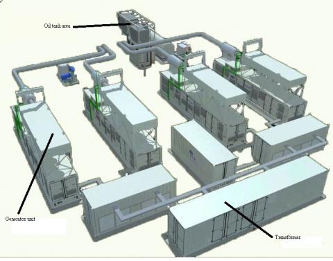
At present, the box-type power station is divided into three parts: 1. The generator set and the container are 7 meters apart, arranged in rows and reserved for maintenance access. 2. The tank area is centrally arranged and transported to each generator container through pipes. 3. Transformer also used centralized arrangement. Site layout shown in Figure 1.
Figure 1. Distribution of box-type substation four units
The numerical simulation of the outflow field of the box type power plant is carried out in the area of the limited air flow field around the generator set,As shown in Figure 2。Boundary conditions are given on the boundary of the region, and the surface of the four generator unit is set as the temperature wall condition, T=293K. The air temperature in the basin is set at 318K, and the bottom of the power station is set as the insulation wall. First of all, in order to verify the correctness of the model, we only simulate the distribution of the thermal field in the box-type power station without wind speed. Therefore, the other five walls of the power station are set as the temperature wall, T = 273K, as shown in Figure 3. Next, speed entry and pressure exit conditions will be added on the left and right sides of the station respectively.
Figure 2. Simplified geometric model of box-type substation four units
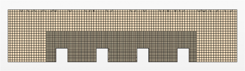
2.3 mesh model
Figure 3 is a cross-section of the grid. The grid is generated by Trimmer of STAR-CCM +. In the power station, two boundary layer grids are generated. Local grids around the unit are encrypted and the final grid is about 310,000.
Figure 3. Mesh model of box-type substation four units
3.1 Analysis of results of vertical parallel arrangement
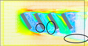
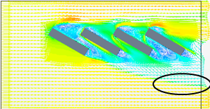
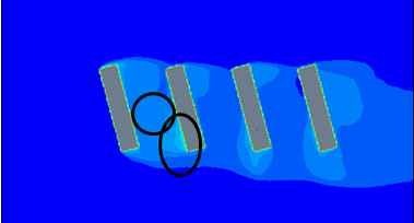
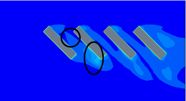
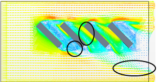
Figure 4 and figure 5 show the distribution of the velocity field and the external flow field of the box type power station under the condition of natural ventilation. As shown in Figure 4, the air flow velocity is very small in the circle ,In Figure 5, the temperature of the outflow field of the circle is relatively high, formed a "heat island effect". Therefore, the temperature rise between the container box, mainly because the air flow between the boxes.
Figure 4. Velocity distribution of outflow field
Figure 5. Temperature distribution of outflow field
3.2 Velocity distribution under natural ventilation
According to the principle of louver ventilation[13],the container group is arranged in a certain inclination angle, as shown in figure 6.Figure 7 is the view of the velocity distribution of the flow field in the container with different dip angle under the condition of natural ventilation.
Figure 6. Schematic diagram of optimization scheme of box-type substation four units
Tilt angle is 15 degrees
Tilt angle is 30 degrees
Tilt angle is 45 degrees
Tilt angle is 60 degrees
Figure 7. Velocity distribution of flow field at different inclined angles under natural ventilation
As can be seen from the figure, with the increase of the inclination angle, the two air currents flowing through the containerⅠflow down to form a convection position. In addition, with the increase of the inclination angle, the convection between the Ⅱ、Ⅲ and Ⅲ、Ⅳ is gradually weakened until the air flows through the container after the air flow through the Ⅱ、Ⅲ container. Instead of these, small convections are generated at both ends of containers II and III. In addition with the increase of the inclination angle, the convection zone at the bottom of the container extends downward, and the whole airflow extends downward.
In conclusion, the inclined installation of the container group can promote the flow of air flow between the containers, thereby reducing the temperature of the container.
3.3 Velocity distribution under natural ventilation
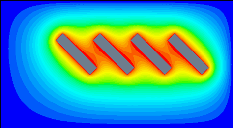
Figure 8 is the view of the temperature distribution of the flow field in the container with different dip angle under the condition of natural ventilation. It can be seen from the figure that the temperature distribution area of the tank group with 15 ° inclination is larger than 0 ° and 30 ° is larger than 15 °, but 45 ° is smaller than 30 ° and 45 ° is smaller than 60 °. The minimum temperature distribution area is 45 ° dip tank group. It is not difficult to see that as the inclination increases, the area affected by the heat dissipation of the container first decreases and then increases. In addition, from the temperature distribution, the temperature between containers of 15 ° inclination is lower than that of 0 °, that of 30 ° is lower than 15 °, that of 45 ° is lower than 30 °, and that of 60 ° is higher than 45 °. With the increase of the dip angle, the temperature of the container first decreases and then increases. The high temperature region between Ⅰ and Ⅱ containers gradually decreased with the increase of inclination until it completely disappeared at 60 ° inclination but resulted in a new high temperature zone at 60 ° inclination. With the increase of the inclination angle, the high temperature region of the container is transferred gradually.
Tilt angle is 15 degrees
Tilt angle is 30 degrees
Tilt angle is 45 degrees
Tilt angle is 60 degrees
Figure 8. Temperature distribution of flow field at different inclined angles under natural ventilation
In summary, the layout of the louver should choose the proper angle in order to avoid excessive inclination (small vertical distance between the boxes) caused by temperature increased again.
3.4 The temperature distribution of no wind condition
Figure 9 shows Temperature distribution of flow field at different inclined angles under windless conditions. As can be seen from the figure, with the increase of the inclination angle, the temperature of the container group increases gradually, and the temperature of the box is equal to that of the outer wall of the container at the angle of 60 degrees.
Tilt angle is 15 degrees
Tilt angle is 30 degrees
Tilt angle is 45 degrees
Tilt angle is 60 degrees
Figure 9. Temperature distribution of flow field at different inclined angles under windless conditions
According to the above analysis, the use of louver-type arrangement not only to choose a reasonable inclination, but also comprehensive consideration of the box temperature distribution in the case of no wind and natural ventilation case.
3.5 Optimization scheme design
According to the front for natural ventilation and wind ,different distance, angle and speed[14]to analyze the velocity and temperature distribution of the container,ignoring the effect of wind speed in the optimization process, Select the container spacing L and tilt θ angle as the optimization parameter. Then, by using the orthogonal test method to optimize two parameters in the case of natural ventilation Finally, verify under the temperature distribution whether can meet the requirements in no wind case.
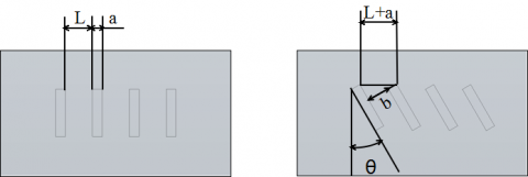
Figure 10. schematic diagram of optimization parameters
When the container group is installed at an angle, in order to facilitate the value, the vertical distance b between the containers instead of the vertical installation spacing L, a is the container width, as shown in Figure 10. The conversion relationship between L and B is as follows:
$L=b+\text{a}/\cos (\text{ }\!\!\theta\!\!\text{ -a})$
The container spacing of B and the θ were optimized, specific programs are shown in Table 1. The composition of 16 kinds of container group was calculated, the speed and temperature distribution were analyzed, and the best combination of parameters was selected.
Table 1. Orthogonal Optimization of container installation parameters
|
Tilt angel α/°
Spacing b/m |
15 |
30 |
45 |
60 |
|
7 |
case1 |
case5 |
case9 |
case13 |
|
8 |
case2 |
case6 |
case10 |
case14 |
|
9 |
case3 |
case7 |
case11 |
case15 |
|
10 |
case4 |
case8 |
case12 |
case16 |
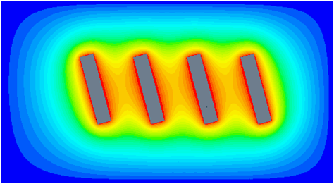
Figure 11. Velocity distribution of flow field at b=8m、θ=45°
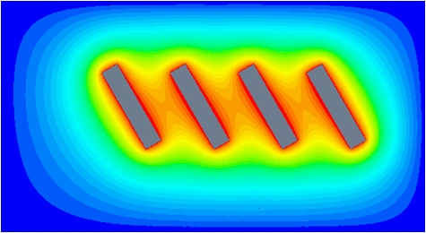
Figure 12. Temperature distribution of flow field at b=8m、θ=45°
Through calculation and comparison, the temperature distribution is good at b = 8m and θ = 45 °, and the installation area does not increase obviously. The velocity distribution and temperature distribution of the external flow field are shown in Fig. 11 and Fig. 12. At the same time, it is verified that there is no obvious high temperature zone between the containers under no wind condition, so the two optimization parameters were determined to be 8m and 45°.
According to the blinds theory, this paper puts forward the optimization scheme for the layout of the heavy oil box type power station, and the numerical simulation of the outflow field is carried out. The temperature field distribution and air flow of the box-type power plant are analyzed. The conclusions are as follows:
1) The box-type power station with louver structure can promote the flow of air between the containers and thus reduce the temperature between the containers. However, the angle of inclination should be chosen reasonably to avoid the temperature in the chamber rising again due to the excessive inclination. In addition, the temperature distribution between the boxes under no wind and natural ventilation should also be considered comprehensively.
(2) The method of orthogonal test is used to optimize the scheme. The temperature distribution is best at b = 8m and θ = 45 °. The installation area did not increase significantly; there was no significant hot zone between containers in a windless state. So determine the optimization parameters for b = 8m, θ = 45 °.
(3) The calculation results provide the basis for the heat radiation of the box type power station, so as to improve the operation efficiency and reduce the cost of the station.
[1] Zhao H, Pang Z, Feng B. (2008). Research and Development of 500GJl-PwT Container--Generating Set. I.C.E. & Power Plant 25(5): 32-33. https://doi.org/ 10.3969/j.issn.1673-6397.2008.05.008
[2] Li Y, Shu N, Han B. (2012). Study of optical cables selecting and laying in smart substation. Water Resources and Power 30(3): 167-169. https://doi.org/ 10.3969/j.issn.1000-7709.2012.03.050
[3] Zhao R, Meng H. (2013). Design of the Container for 2800 kW Containerized Generator Set. I.C.E. & Power Plant 30(1): 11-18. https://doi.org/ 10.3969/j.issn.1673-6397.2013.01.004
[4] Taghikhani M, Gholami A. (2009). Prediction of hottest spot temperature in power transformer windings with non-directed and directed oil-forced cooling. International Journal of Electrical Power & Energy Systems 31(7-8): 356-364. https://doi.org/ 10.1016/j.ijepes.2009.03.009
[5] Taheri S, Vahedi A, Gholami A, Taheri H. (2008). Estimation of hot spot temperature in distribution transformer considering core design using FEM. International Conference on Power and Energy 2008. 1408-1413. https://doi.org/ 10.1109/PECON.2008.4762699
[6] Chatzidimitriou A, Chrissomallidou N, Yannas S. (2006). Groud surface materials andmicroclimates in urban open spaces, 23rd Conference on Passive and Low Energy Architecture, Geneva, 1426-1434.
[7] Doulos L, Santamouris M, Livada I. (2004). Passive cooling of outdoor urban spaces. The Role of Materials Solar Energy 77(2): 231–249.
[8] Jang J, Chen C. (2015). Optimization of louvered-fin heat exchanger with variable louver angles. Applied Thermal Engineering 91:138-150. https://doi.org/ 10.1016/j.applthermaleng.2015.08.009
[9] Gorman J, Carideo M, Sparrow E, Abraham J. (2015). Heat transfer and pressure drop comparison of louver- and plain-finned heat exchangers where one fluid passes through flattened tubes. Case Studies in Thermal Engineering 5(1): 122–126. https://doi.org/ 10.1016/j.csite.2015.03.002
[10] Ching-Tsun H, Jiin-Yuh J. (2005). 3-D thermal-hydraulic analysis for louver fin heat exchangers with variable louver angle. Applied Thermal Engineering 26(14-15): 1629–1639. https://doi.org/ 10.1016/j.applthermaleng.2005.11.019
[11] Yang L, Qi B, Chen J. (2015). Numerical simulation and analysis on louver arrangements of oblique needle louvered fin. Mechanical Engineer 47(12): 22-24. https://doi.org/ 10.3969/j.issn.1002-2333.2015.12.009
[12] Kou L, Liao S, Liu Y. (2009). Numerical simulation for heat transfer performance of louvered fin. Building Energy & Environment 28(1): 6-9. https://doi.org/ 10.3969/j.issn.1002-2333.2015.12.009
[13] Xie H, Chen K. (2010). Impact of point source height and window Configuration On lndoor air quality. Journal of University of Shanghai for Science and Technology 32(5): 413-417. https://doi.org/ 10.3969/j.issn.1007-6735.2010.05.002
[14] Wan X, Su Y. (2004). Numerical simulation of effect of building structure on natural ventilation in industrial workshops with heaf sources, Ph.D. dissertation, Department of Thermal Engineering, Donghua University, Shanghai, China