OPEN ACCESS
To solve the problem of Auto CAD system in the professional in the field of mechanical design for is not strong, the low efficiency of drawing problem, Auto CAD system is used to provide secondary development environment developed based on Auto CAD operation of general mechanical CAD system—GMCAD. For all the needs of mechanical design of 2D drawing, according to the principle and the function of Auto CAD model and system integration, determine the overall framework of GMCAD system; in refining mechanical structure elements of two-dimensional features, design practice and design standard and specification based on that really set the GMCAD system; Using Auto CAD function expansion, menu customization and program development tools, completed the development of GMCAD system. GMCAD can seamless integration in Auto CAD, and their joint operation, for the design staff provides professional and efficient mechanical design environment, to quickly complete the mechanical structure drawing and annotation, a substantial increase in the efficiency of mechanical design, a good solution to the problem of Auto CAD professional needle of sex is not strong, but also to solve the problems existing in most of the secondary development of the system of general poor, regulate the chaotic, poor portability.
mechanical CAD, Secondary development, 2D graphic entity, drawing settings, dimensioning
The research of CAD technology started in the late 1950s [1]. Although Auto CAD system has enabled designers to free themselves from the traditional mode of designing with paper and drawing pens, and increased the drawing efficiency, yet, the systems still has some certain weak professional pertinence. These issues prominently in the following aspects:
(1) GB did not meet the required specifications established drawing environment, users can before drawing the boundaries of the pattern, layer, line, characters and dimension styles and other environmental parameters complicated settings, and meet the national standard drawing frame and title bar, planning drawing scale. Even with the system function model diagram, it is difficult to meet the actual requirements for complex engineering design drawing environment. This is what our designers’ very difficult problem, also contributed to the normative pattern root causes of poor [2].
(2) No specific drawing tools commonly used in the mechanical structure, resulting in some of the common mechanical structure of complex graphics rendering process, the command sequence variability, parameter input frequently, sometimes even used editing commands and drawing commands to complete with, greatly reducing the draw mechanical engineering drawings effectiveness [3].
(3) Mechanical design label forms, strict format. Annotation capabilities of Auto CAD system can not meet the needs of the actual design, for some formatting labeling, tagging and editing must be a combination of ways, it requires the user to accumulate a wealth of experience on the basis of drawing gradually worked, but also result in labeling reduced portability pattern diversity, to a certain extent on the way, but also greatly affected the pattern of labeling efficiency [4].
Auto CAD system has these problems, it not only reduces the Auto CAD system application results in the field of mechanical design, also gives users the trouble, and reducing the efficiency of the system. To solve this problem, the secondary development based on General CAD system is an approach that needs a small investment but enjoys a quick return on the investment [5]. Auto CAD has offered some secondary development tools such as Auto LISP, Object ARX, ActiveX and so on [6-8], with which users can customize the system interface, programme and develope the functions of the system, and set up a designer-friendly designing environment. Informed through surveys and read large amounts of data, at present, most users use Auto CAD system mechanical design, use of secondary development methods based on Auto CAD system to establish a professional design environment, in order to improve the efficiency of the design drawings and implement industry standards; Some small-scale professional CAD software vendors have also developed systems running on Auto CAD mechanical CAD system. From the development of technology and the practical effects, these systems exist the following common problems [9-12]:
(1)Corporate design personnel requirements increase, need to be equipped secondary professional Auto CAD system developers to customize the work co-ordinate system, or entrust professional CAD systems supplier development, improve the management costs.
(2)Auto CAD system development based foundation dedicated design environment designed only for the needs of the enterprise, it does not have universal application, and promote the use of low-value system.
(3)Systems development no uniform standard, developed systems often contain many of the enterprise-specific environmental parameters, Draw a complex engineering drawings, graphic link complex entity, engineering drawings often appear after departing from the phenomenon of the enterprise CAD environment can not be displayed properly, to a certain extent, it affects the scope and effectiveness of technology exchange.
(4)The system of operating habits and command operation mode is different from the Auto CAD system, it caused the difficulties of the designers use, but it weakened the effect of the application of the system itself.
(5)Their own customized CAD systems are generally not formed a complete system of procedures, it does not have the automatic installation and configuration features, Auto CAD system version of dependency is high, resulting in upgrades and portability of the system is reduced.
To solve the above problems, in the overall refining common mechanical structure, on the basis of mechanical drawings summarize and technical personnel design custom label law, this paper has made an elaboration on the developing principle and method of the two-dimensional General mechanical CAD system (GMCAD) developed with Auto LISP and tools on the basis of Auto CAD. The system has offered designers a suitable, convenient, fast and efficient mechanical designing process, and a desired designing environment which is in conformity with the mechanical designing standard and specifications.
2.1 The overall framework of GMCAD system
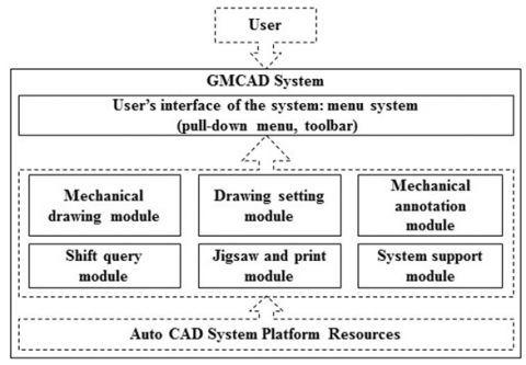
The GMCAD system mainly consists of six modules: “drawing setting”, “mechanical drawing”, “mechanical annotation”, “shift query”, “jigsaw and print” and “system support”, and each module includes several commands. The function of the system covers drawing, dimensioning, drawing environment initialization and the jigsawing and printing as well as the functions of the environment shifting and the graph or data query. The construction and function of GMCAD system module are seen in Figure 1.
The same with Auto CAD system operating modes, the function of GMCAD system is embodied by various commands to load and Auto CAD system user interface and drop-down menu in the toolbar. User by picking these commands, follow the prompts to input various data commands to complete two-dimensional graphics generation. In addition, to ensure the mechanical design of the strict implementation of standards and norms, GMCAD system also provided many of the system environment variables, to identify and control various drawing environment, ensures that designers design process is completed in accordance with established drawing.
Figure 1. The construction and function of GMCAD system module
File GMCAD system self-contained and runs on Auto CAD system. File system system consists of “support and template files” and “Command definition file” of two parts, detailed structure and function of the file are shown in Table 1. After system installation, it will be independent of the above documents stored in a folder and independent of the Auto CAD system, after the establishment of the association is initialized with Auto CAD system, to achieve synergy run both systems.
Table 1. GMCAD system file structure and functions
|
File system |
File type |
File functions |
|
Support and template files |
Menu File |
GMCAD system definition file drop-down menu and toolbars, automatically loaded when you start Auto CAD |
|
Linear file |
GMCAD system of Non-continuous-line style definition files used by the system in line with GB |
|
|
Icon files |
Icon Definition GMCAD toolbar buttons used all the tools |
|
|
Slides and slide library file |
Icon Definition the use of dialog box |
|
|
Graphics template files |
Various graphics drawing environment initialization template definition is used, some of the environmental parameters have been set up in the template is completed |
|
|
Command definition file |
Auto LISP file |
Drawing and annotation command definition GMCAD system is the core of the file system |
|
Dialog Definition File |
System commands are used to define a dialog box |
2.2 System development method
2.2.1 Development of the Command System
For the convenience of users, in line with Auto CAD system working mode, the form of the GMCAD system commands of all functions are available. This system is used to write programme files for each command with Auto LISP. The development of each command is finished through the process of “definition of command function”, “designing habit analysis”, “definition primitive model”, “determination of geometric model”, “determination of command parameters and mode of input”, “programme and modulate programmes” etc. GMCAD will be normally used after the auto loading of the command definition programme of GMCAD when Auto CAD is opened. System command details are shown in figure 2.
Figure 2. GMCAD system command definition process
2.2.2 Development of the resource files
GMCAD resource supporting files mainly serve for the system menu, the auto loading of the programme, the definition of the dialog box and the definition of the drawing environment etc. The resource files have made into those separate ones programmed in accordance with the expansion of the Auto CAD functions and with the rules of the secondary development, and they can be accessed and loaded automatically when the system is started up. In order to ensure the integrity of the Auto CAD system menu, GMCAD system menu is developed separately [13]. Details of the system resources and their support files are to be seen in Table 2.
Table 2. GMCAD system resource and support file list
|
File names |
Specifications of the files |
|
GMCAD.MNU |
system menu source files, the pull-down menu and toolbar used by the definition system |
|
GMCAD.MNL |
system menu files, auto loading of the completion of all commands of the GMCAD, and the auto setting of the environment variables |
|
*.BMP |
definition files of the button icon on the toolbar |
|
*.SLD |
slide files used in the dialog box |
|
*.SLB |
slide library files |
|
GMCAD.LIN |
linetype definition files of the system |
|
*.DWT *.DWG |
drawing and template files, defining drawing frame and title bar |
3.1 Drawing setting modules
3.1.1 Composition of commands and their functions
The principal function of this module is to set up the drawing environment which is in conformity with the requirement of GB, and ensures the standard and unification of the format of the mechanical drawings. This module includes two groups of commands:
(1)Command of “initialization”: set the size of the drawing, the Drawing scale, the direction of the drawings and the type of the drawings, insert the drawing frame and title bar, and set layers, linetype, colour, line width, text styles and the dimension styles. System initialization function in the CAD system is completed by the “Setting the graphing environment” command. After issuing the command, System dialog box will appear as shown in Figure 3, users simply need to select the corresponding content, you can quickly complete the mapping work environment settings, the system will automatically complete the setting of the parameters, and to establish full compliance with the requirements of GB drawing environment, to ensure a unified design specifications and formats.
Figure 3. "Setting the graphing environment" command run dialog box
(2) Command of “style shift”: concerning the fact that users need to use the annotation command of Auto CAD, the “style shift” is thus set so that the system will automatically shift to the corresponding style when the MCAD system annotation command is used.
3.1.2 Development of commands
The core command of the drawing setting module is “initialization”, so the following key problems are solved in the development:
(1) The implementation of the GB standard: the formats of the drawing size, scale, frame of the drawing and the title bar are set according to the requirement of the GB standard, and then they are solidified into the template files.
(2) The running mode of command: standard data available for selection can be offered by the adoption of dialog box or in order to enter into the programme to finish the setting, the parameters can be accessed by means of manual input. This mode ensures that the GB data can be implemented correctly and the drawings can be standardized, and that the data can be easy to use because of its visual features.
(3) The processing of the drawing scale: the drawing scale can be solved by means of shifting the drawing space without regard to the drawing scale (that’s 1:1 drawing). The graphics primitives are divided into two types [14]: “graphics primitive affected by the drawing scale” and “graphics primitive unaffected by the drawing scale”. The former is finished in the model space, and the latter is done in the drawing paper space.
3.2 Mechanical drawing module
3.2.1 Composition of commands and their functions
The mechanical drawing module, which has overcome the weak professional of Auto CAD system pertinence, offers rich typical mechanical drawing commands. The major commands and their functions included in the module can be seen in Table 3.
Table 3. The major command and function of mechanical drawing module
|
Commands |
Command functions |
Command parameters and modes of input |
|
Center line |
Automatically drawing of the symmetric center lines and axes in conformity with the GB requirements |
The entity endpoint of the center line, snap input or keyboard input |
|
Angle line |
Drawing of straight lines at specified angles |
End point and angle of the line, snap input or keyboard input |
|
Outside thread |
Drawing of views of the outside thread |
Major diam and insertion point, dialog box selection and snap input |
|
Inside thread |
Drawing of views of the inside thread |
Major diam and insertion point, dialog box selection and snap input |
|
Threaded connection |
Views of the assembly of threaded connection to be inserted |
Types, specifications and insertion point, dialog box selection and snap input |
|
Rolling bearing |
Views of the rolling bearings inserted |
Model number and insertion point, dialog box selection and snap input |
|
Hole |
Drawing of different kinds of holes(light holes, threaded holes, and taper holes) |
Types, specifications and insertion point, dialog box selection, keyboard input and snap input |
|
Groove |
Drawing of various kinds of grooves (thread tool escape, relief grooves for grinding wheels etc.) |
Types, specifications and insertion point, dialog box selection, keyboard input and snap input |
|
Step shaft |
Drawing of the views of different step shaft sections |
Types, specifications and insertion point, dialog box selection, keyboard input and snap input |
|
Key groove |
Drawing of the views of the shaft and the keyway on the hole and its sectional view |
Types, specifications and insertion point, dialog box selection, keyboard input and snap input |
|
partial enlarged drawing |
Automatical generation of the partial enlarged drawing in the specified area |
Range and insertion point, snap input |
3.2.2 Development of commands
Design drawing habits, primitive geometry, command parameters and input mode is a major factor in determining a command operation mode, and the key is the system tool can effectively improve the efficiency of drawing [15, 16]. Define the process in accordance with the commands shown in Figure 2, develop key technologies GMCAD system mechanical drawing module for each command is as follows:
(1)Determination of commands and their functions: the function module point (that’s “command”) and the range of the function are extracted in integration with mechanical designing and drawing standards, the rules of designing, typical mechanical structure and the operation habit of designers; the differences between the functions of GMCAD system and of the Auto CAD system are found out in accordance with the principle of “covering all the requirements for mechanical designing and drawing” and the coverage of the functions of the command examination; eventually determined are the commands and the range of the functions included in the GMCAD system mechanical drawing modules. Command system to determine their functions GMCAD drawing module contains an important part of system planning, which directly determines the function of the system is fully meet user needs and system can provide users with comprehensive, efficient design drawing environment. Analysis of Auto CAD system graphics commands and its functions, with the simple point,line and plane graphics to construct a complex two bit line block diagram, to express the complex structure of the projection. Although this planning method has achieved the goal of drawing the most complicated figure with the least command, but also has the problem of complicated operation and low drawing efficiency [17]. To this end, we have from several aspects to collate and summarize the GMCAD system drawing commands and their functions:
Planning drawing commands from mechanical parts classification [18]: It is a source of GMCAD system drawing commands. GMCAD system contains the center line, the angle line, the cylindrical shaft hole, the step shaft hole, the cone axis and so on drawing the command to come from this.
Drawing of standard structure: Will these representations are arranged into GMCAD system's function planning out such as external thread, internal thread, thread axial view, threaded hole, thread fasteners keyway and keyway shaft section, key slot and rolling bearings and so on command.
Drawing of process structure: Such as chamfer, fillet, tool withdrawal groove, the distance slot and hole structure.
Special expression methods in mechanical drawing: GMCAD system will be specified in the format of GB expression in the function of the command, you can quickly complete the drawing work by entering the specific parameters, greatly improving the efficiency of drawing.
(2) Setting up of the “primitive geometric model”: extraction of the primitives based on the function of commands, determination of the graphic entities that form the primitives and their parameters, determination of their geometric relations among these parameters, and the reasoning of their mathematic relations together set up the geometric models of the command primitives. “Geometric model” is a description of the geometric relations and topological relations between the parameters of the mechanical structure view unit [19]. The drawing command of GMCAD system is to call the CAD Auto system command to work, the parameters of the operation of the command is the geometric and topological data of the target graph. These parameters are divided into two types, one is the driving parameter, the other is the drive parameter; The geometric relations and topological relations of the unit graph parameters are the general term of the relationship among the parameters, the geometric relations, and so on. Therefore, the process of establishing the geometric model of a graphic element is the process of determining the sequence of drawing commands, driving parameters and driving parameters, and determining the geometric and topological relations between the parameters. Specific as follows:
Determine the drawing command sequence: According to the graphics object to be drawn, we need to design a sequence of commands, which is simple, quick and stable. Then, according to the determined command sequence, the parameters are extracted, and the parameters are the driving parameters and the driving parameters. It is the basis of establishing the geometric model of the geometric model, and it also decides the operation mode and mechanism of the system command.
Determine drive parameters: Drive parameters are the running parameters of the drawing commands of the GMCAD system, which are used by the system operator to enter the system through the operation interface of the system command. Driving parameters are read by the system, will be used as the basis for the calculation of the drive parameters, according to determine the geometric relations and topological relations automatically calculated to be driven parameters. Driving parameters are determined, the function of command, the mode of operation, the nature and function of the graphic object, the source of the parameters and so on are needed.
Determine the drive parameters: The driving parameter is calculated by the driving parameter according to the geometric relation and the topological relation, and the calculation process is completed automatically by the system program. The drive parameter is the direct parameter that the system drawing commands to run, so the determination of the drive parameters mainly considers the requirement of the Auto CAD system command operation, and fully consider the various situations of the command operation.
The geometric and topological relations between the parameters are determined: Establishing the geometric and topological relations between the drawing parameters is the core of the geometric model, which refers to the function relation between the driving parameters and the drive parameters. GMCAD system can be based on these functions, the parameters of the system drawing commands are automatically calculated on the basis of receiving the driving parameters. The geometric and topological relations of geometric elements are determined, which mainly consider the position relation between the driving parameters and the drive parameters, the attribute of the drawing object, the projection relation between the view and the drawing standard.
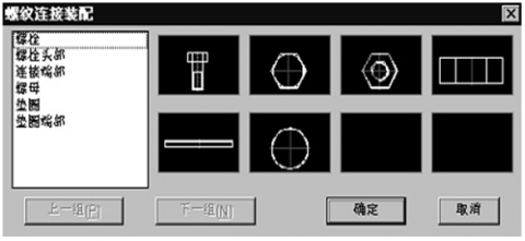
(3) Determination of the “command parameters and the method of their input”: command parameters, the entry parameters of the command, are used to finish the graphic drawings according to the drive command programme of the geometric module. The generality of the system, the convenience and the visual features of the input mode of the command system parameters are taken into considerations. Command parameters of the input mode determines the system's ease of use and drawing efficiency, but also determines the system's portability and industry adaptability [20]. Mapping analysis using design parameters of the source can be seen, for the source to the product specifications, design calculation and industry standards to regulate the parameters, with the characteristics of the industry as a result of these data, it often has limitations, and therefore should not be the curing parameter to the system program, taken interactive input supplied to the system; The source in the national standard data, because it is not affected by restrictions on the industry, so you can these curing data into the system database, the data used to take selected in the dialog box, which is fast and intuitive. The establishment of the above principles, can very good assurance system GMCAD has good portability and wide industrial adaptability, flexibility is also losing system for the mechanical design to provide professional design environment based on. The parameters of the GMCAD system input form mainly include keyboard input, dialog box selection and graphics capture; GMCAD system work when the user interface mainly includes the CAD Auto command line prompt, dialog box and edit the graphic entity. Therefore, when determining the operation mode of each command, the system should consider the factors such as drawing custom, the source of the parameters and the editing object, and so on. Table 4 gives the parameters of the GMCAD system drawing module command input mode. Figure 4 shows the GMCAD system commands to run the dialog box example, which is an important way to enter the system parameters.
Table 4. The selection principle of the command parameter input mode of the mechanical drawing module
|
Command parameter source |
user interface |
||
|
Auto CAD command line |
dialog box |
Screen display graphics |
|
|
Product specifications |
keyboard entry |
keyboard entry |
|
|
design calculation |
keyboard entry |
keyboard entry |
|
|
General standard specification |
|
Select list |
|
|
Industry standard specification |
keyboard entry |
keyboard entry |
|
|
Current pattern |
|
|
Capture primitive |
Figure 4. Draw the run dialog for the threaded fastener command
3.3 Mechanical annotation module
There are strict requirements for the annotation format (such as the height, the width and the character spacing) of the Chinese characters in the sample drawings as per the standards of the national Technical Drawing and Mechanical Drawing [21] so as to make up for the shortcomings of the annotation functions of the Auto CAD system. The main functions of the mechanical annotation module of GMCAD system include the structure size, the technical requirement, numbers of the parts, lists and title bars and other annotation functions. The content properties are characters and symbols, which meet the requirement of the general mechanical drawing annotation. Details of the command and its functions of the mechanical annotation model are seen in Table 5.
Table 5. Details of the command and its functions of the mechanical annotation model
|
Command |
Command function |
|
Chamfer size |
Annotation of chamfer of different directions and sizes (including chamfers not drawn) |
|
Fillet size |
Annotation of transitional fillets of different directions and sizes (including fillets not drawn) |
|
Small linear size |
Annotation of small spaced linear of different directions and sizes (supporting arrows and dots) |
|
Taper and slope |
Annotation of symbols and values of taper and slope |
|
Hole size |
Annotation of different simplified holes and special sizes, including suffix symbols |
|
Dimension tolerance |
Annotation of the dimension tolerance of different kinds, supporting auto annotation of the values of the middle deviation, upper deviation and lower deviation in “priority and commonly-used fits” |
|
Fit symbols |
Annotation of the fit symbols of different kinds, supporting the selection list of “priority and commonly-used fits” |
|
Geometric tolerance |
Annotation of symbols and values of the geometric tolerance(the original “tolerance of form and position”), supporting the selection and input of parameters |
|
Base symbols |
Annotation of the base symbols used in the geometric tolerance |
|
Surface texture |
Annotation of surface texture symbols(the original “surface roughness”) of different forms, positions and directions, supporting selection list and input of parameters |
|
Welding symbols |
Annotation of welding symbols of different forms, positions and directions, supporting selection list and input of parameters |
|
Superscript and subscript |
Annotation of characters or symbols with superscripts and subscripts |
|
Greek letters and Roman letters |
Annotation of Greek letters and Roman letters |
|
Technical requirements |
Writing technical requirements, supporting pre-maintenance and selection required by the technology |
|
Part number |
Compiling part numbers of different forms, positions and directions, including single serial numbers, the serial numbers of the centralized horizontal and vertical compiling, and simultaneously filling in the corresponding part list |
|
Title bar |
Filling in the title bar |
The following key technologies are used in the development of the mechanical annotation of commands:
(1) Shift of “annotation of environment and parameters”: the characters and symbols in the drawing annotation format are the primitives which are “free from the influence of the drawing ratio”. Each of these mechanical annotation of commands is programmed with the technology of auto shift of drawing space and parameter annotation so as to ensure the correct running of each of the commands and the standard of the annotation, and to automatically resume to the previous environment after the command is finished or intermitted.
(2) The control of “dimension styles and position”: in order to facilitate users, the annotation of command offers users more opportunities to control command running to annotate flexibly with the adoption of “flexibile geometric modeling technology”; as to commands with comprehensive annotation functions, the flexible dialogue box annotation format is used.
(3) The control of the “annotation of contents”: the nonstandard data is input by the use of keyboard or by screen capture; the standard data is input by the use of the selection list in the dialog box, and at the same time this control supports the auto query for logical data; the data between the above ones can be input either by first pre-maintenace input, then by selection, or by direct input; it also supports auto dimension measurement and manual modification.
(4)The determination of the annotation model: Auto CAD system of annotation command can not meet the mechanical drawings marked demand, so GMCAD system annotation commands in addition to functional annotation using the Auto CAD system, but also the use of drawing commands to achieve the marking function. So in the GMCAD system, part of the size of the mark is actually drawing graphics, and graphics modules are the same, but also need to establish a marking model. The method of determining the model is adopted and the same method is used to establish the “geometric model of the graphic element”. First determine the sequence and parameters of the labeled sequence, and then determine the driving parameters and drive parameters, and then determine the geometric relations and topological relations of the parameters, here is no longer detailed description.
To extend the functionality of CAD Auto, the system provides users with a wealth of two development tools [22]. GMCAD system development mainly use Auto CAD system built-in auto LISP programming language, and use the system template customization, customized menu and dialog customization tools, completed the development of resource file GMCAD system, system menu, command, compile tools to complete the compilation of the program code, the use of install program making software produced GMCAD installation procedures.
4.1 GMCAD resource system customization
The GMCAD resource system mainly includes three parts, which are the automatic loading resources, the icon type support system and the template file. Their development process is as follows:
(1) Automatic loading of resources: Mainly includes the operation parameters of automatic loading and the automatic loading of the command program. The normal operation of the GMCAD system, the need for a part of the CAD Auto system variables in advance setting; at the same time, the use of LISP Auto development of the command also need to be pre loaded in order to use. To this end, the development of the MNL file, the system variable settings and procedures for the preparation of the document file in the file. MNL file with the CAD Auto start automatically run, one by one to execute each statement contained in the file, to achieve automatic assignment of system variables and automatic loading of the command file.
(2) The development of the icon type support system:
Icon file is a predefined bitmap file (BMP file), it is used to support the use of the GMCAD system toolbar. GMCAD system uses a 16 x 16 pixel image definition button icon. Use the Auto CAD system graphics rendering, and transformed into a slide file (SLD) optional icons as dialog box, slide file was compiled into a slide library file (SLB) can in Auto CAD system startup automatic loading using.
Auto CAD system comes with line library contained in the linear definition does not conform to the requirements of GB. Therefore, GMCAD in accordance with Auto CAD lines defined rules defined their own line, including mechanical drawing of center line, dotted line and double dotted line.
(3) The development of template files: GMCAD the template file (DWT) technique is established in line with the GB requirements of various kinds of breadth of blank template file and start system will automatically load, in plot setting, the system according to the user's selection automatically load the corresponding blank template.
4.2 GMCAD development of system commands
(1) The definition of system commands: All commands of the GMCAD system are developed using LISP Auto language programming. On the basis of the establishment of the “geometric model of the geometric model”, the program code can be written in a plain text editor. Each command's program code includes the program description, function definition, variable definition, drive parameter input, calculation of the drive parameters, call Auto CAD system command drawing and the end of the program, and so on. After the completion of the preparation of the program file, save as LSP files, and then compile. Compiled files can not only improve the running speed of the program, but also improve the confidentiality of the code. The command program code in the GMCAD system to start at the same time automatically loaded, can be used at any time.
(2) The development of the dialog box: In most of the GMCAD command operation process, the need to call the dialog box, so that users select the appropriate parameters, improve the efficiency of drawing parameters input. The definition of the dialog box file using the DCL language, each dialog box corresponds to a definition of documents, and the establishment of a LSP file with each other calls [23].
4.3 GMCAD system menu development
System menu is an important channel for GMCAD system to issue commands. The system menu includes two kinds of menu and toolbar, the user can click the drop-down menu item and button on the toolbar to activate the corresponding command.
(1) The custom of the drop down menu: CAD Auto system in accordance with the definition of the drop-down menu rules, separate the preparation of the drop-down menu to define the text, and save it in a separate system menu source files (MNU files). The drop-down menu is also developed in accordance with the custom classification, that is, according to the command function classification will be similar to the same command definition in the same drop-down menu; As far as possible the use of a single level menu, up to use the two menu to facilitate the use of users. After the menu source file is compiled to form a menu file, the GMCAD system is automatically loaded at startup, the drop-down menu can be displayed in the Auto CAD main interface, the user can directly use.
(2) The definition of toolbar: In accordance with the CAD Auto system toolbar definition rules, using the CAD Auto system toolbar definition tool defines the GMCAD toolbar. The toolbar is defined as a function of the drop-down menu, which contains a number of tool buttons. The icon of each button is provided by the resource system, and is linked with the command of the GMCAD system. The corresponding command can be activated by pressing the button. The toolbar's definition code is also written in the menu source file (MNU file). After the compiler automatically loaded with the system to start [24].
Based on Auto LISP and the secondary developing tool of Auto CAD, GMCAD system has set up a comprehensive mechanical designing and drawing platform, which conforms to the mechanical designing habit and to the professional requirement, and which combines the functions of standard designing and drawing, annotation, data query into one, and this system has laid a foundation for users to increase their drawing efficiency and focused designing in the real sense. This system has provided its users with plenty of designing tools for mechanical structure drawing and annotation which has increased the designing efficiency so that the standardisation of the drawing has been ensured, and that the share and management of the drawing data has been realised. The system has included the standard data for users to inquire so as to free themselves from the trouble of checking the manual. Applied practices show that GMCAD has offered a powerful extension for Auto CAD system to be used in mechanical designing field, and that it has provided its users with a general 2D mechanical designing and drawing environment and has solved the weak professional pertinence in the Auto CAD system.
(1) The integrated use of Auto CAD system of secondary development tools, the establishment of a composed of menu system support, file system and command system system design platform is solve Auto CAD professional for the important means. Only by adhering to the principles of independence, universality and portability, the system can overcome many disadvantages of the existing two development system.
(2) The core work of system development is to extract the function and order of the system on the basis of the induction and arrangement of the mechanical structure drawing. Functional refinement should adhere to the principle of mutual complement with Auto CAD, avoid large and fully replace the trend of Auto CAD function, but also to prevent the emergence of functional blind spots.
(3) The emphasis of system development is the establishment of geometric model of each element, which it determines the operation mode, operation efficiency and ease of use of the system command. Starting from carding machinery design habits, on finding based on the nature of the primitives, combined with Auto CAD system optimization method of drawing, determine the drawing command sequence, sort out the required parameters, determining the driving parameters and parameters to be driven, and finally establish the parameters of the geometry and topology relation.
(4) Establishing a complete and independent system, and doing a good job with the Auto CAD system of seamless integration. System should be composed of resource system, command system, menu system and template system, these systems can work together to form a complete system, which does not destroy the integrity of Auto CAD system. At the same time, the use of technical means to do a good job of the association between these systems, do a good job in system and Auto CAD system integration and integration.
(5) The system file is best to compile, both to enhance the loading and running speed, but also to improve security; It should make independent setup can realize system automatic installation, reducing the difficulty of installation, it can also use the system of authorization management, conducive to the protection of intellectual property rights.
[1] Xiuzi Ye, Wei Peng and Lili HE, “current research issues and future development trends of CAD technologies an industrial perspective,” Journal of Computer Aided Design & Computer Graphics, vol. 15, no. 10, pp. 1194-1199, 2003. DOI: 10.3321/j.issn:1003-9775.2003.10.002.
[2] Xiande Xu, “Application of auto CAD secondary development in railway bridge pier design,” Journal of Railway Engineering Society, vol. 185, no. 2, pp. 56-60, 2014.
[3] Peien Feng, Wenping Chen and Shuangxia Pan, “Complex mechanical CAD System development strategy and application examples,” Mechanical Engineering, no. 4, pp. 6-9, 1989. DOI: 10.3321/j.issn:1004-132X.1989.04.002.
[4] Chaoyong Guo and Jianbo Huang, “Design and realization for auto-dimensioning system of technical requirements under auto CAD,” Modern Manufacturing Engineering, no. 8, pp. 34-36, 2004.
[5] Feng Liu, Zhijun Zhou and Lijuan Li, “The pretreatment technique and its application in parametric design of mechanical CAD,” Machine Design, no. 8, pp. 11-13, 1997. DOI: 10.13841/j.cnki.jxsj.1997.08.004.
[6] Jinxi Zhang, Visual Basic and Anto CAD Secondary Development, Beijing: Tsinghua university press, 2002.
[7] Tegarden. David P. and Sheetz. Steven D., “Cognitive activities in OO development,” International Journal of Human Computer Studies, vol. 54, no. 6, pp. 779-798, 2001. DOI: 10.1006/ijhc.1999.0462.
[8] F. Barbier and B. Henderson-Sellers, “Object modeling language: An evaluation and some key expectation for future,” Annals of Software Engineerlng, vol. 10, pp. 67-101, 2000.
[9] Houchun Zhou, “Analysis of mechanical CAD technology in enterprise application,” Machine Design, no. 11, pp. 41-44, 1996. DOI: 10.13841 /j.cnki.jxsj.1996.11.015.
[10] Yu LI and Dingfang Chen, “The development and trend of mechanical CAD techolnogy in China,” Journal of Hubei University of Technology, vol. 21, no. 3, pp. 73-76, 2006. DOI: 10.3969/j.issn.1003-4684.2006.03.026.
[11] Nishui Cai, Huijun Zou and Shigang Wang, “Mechanical product conceptual design-intelligent CAD key technologies,” Machine Design, no. 6, pp. 1-3, 1997. DOI: 10.13841/j.cnki.jxsj.1997.06.001.
[12] Xinxi Wang, “Research on the method for improving the Auto CAD drawing efficiency,” Manufacturing Informatization, no. 12, pp. 58-59, 2012. DOI: 10.3969/j.issn.1002-2333.2012.12.029.
[13] Hui Ling, Auto CAD Efficient Mechanical Drawing Techniques, Xian: Xidian University Press, 1998.
[14] Yuchuan Zhang, “Application and research of technology on component-based concurrent development for mechanical CAD,” Ph.D. dissertation, Dept. Mech. Eng., Wuhan University of Technology, Wuhan, China, 2002.
[15] Yuexin Luo, Shimin Mao and Xutang Wu, “Programming of chart in CAD for hypoid gears,” Mechanical Science and Technology, vol. 18, no. 6, pp. 1025-1029, 1999. DOI: 10.13433/j.cnki.1003-8728.1999.06.055.
[16] Fneg Liu, Zhijun Zhou and Lijuan Li, “Pretreatment technology and application on mechanical CAD parametric design,” Machine Design, no. 8, pp. 11-13, 1997. DOI: 10.13841/j.cnki.jxsj.1997.08.004.
[17] Wenhong Yang, Zhiai Li and Qiulai Wen, “Implementation on configurations of port in parts drawing using secondary development of AutoCAD,” Computer Development & Applications, vol. 74, no. 1, pp. 74-75, 2014. DOI: 10.3969/j.issn.1003-5850.2014.01.023.
[18] Yingchun Hu, Xiaoying Liu and Yizhi Hu, “Parametric design of axes based on typical mechanical parts library in AutoCAD,” Journal of Guilin University of Technology, vol. 34,no. 4, pp. 771-774, 2014. DOI: 10.3969/j.issn.1674-9057.2014.04.029.
[19] S Jayaram, A Myklebust, “Device-independent programming environments for CAD/CAM SOFTWARE CREATION,” Computer-Aided Design, vol. 25,no. 2, pp. 94-104, 1993. DOI: 10.1016/0010-4485(93)90095-6.
[20] Yan Feng, “Secondary development of auto cad standard parts and common parts library creation based on VB,” New Technology & New Process, no. 1, pp. 52-54, 2014. DOI: 10.3969/j.issn.1003-5311.2014.01.017.
[21] Chaoyong Guo and Jianbo Huang, “Design and realization for auto-dimensioning system of technical requirements under auto CAD,” Machinery Manufacturing Engineer, no. 8, pp. 34-35, 2004. DOI: 10.3969/j.issn.1671-3133.2004.08.013.
[22] B. Betting, J. Shah, “An object-oriented program shell for integrating CAD software tools,” Advanced in Engineering Software, vol. 12, no. 30, pp. 529-541, 1999.
[23] Bo Yang, Yanmin Peng and Liang Yang, “The method of achieve linear approximation arc fitting based on the secondary development of AutoCAD,” Intelligent Manufacturing, no. 3, pp. 48-51, 2014. DOI: 10.3969/j.issn.1671-8186.2014.03.038.
[24] Meifa Huang, Mengmeng Xiao and Yonghou Sun, “Research on tolerance design of the assembly dimensional chain based on AutoCAD,” Modular Machine Tool & Automatic Manufacturing Technique, no. 5, pp. 127-132, 2014. DOI: 10.13462 /j.cnki.mmtamt.2014.05.033.